Brüel & Kjaer Vibro AS - 030 User manual

Brüel & Kjaer Vibro GmbH Tel. : +49 6151 428-1400 04.07.2017
Leydheckerstraße 10 Fax : +49 6151 428-1401 C102787.013 / V05
D-64293 Darmstadt E-Mail : [email protected]m Seite/Page/Strona 1 von/of/z 11
AS - 030
Beschleunigungs-Sensor / Acceleration Sensor
Czujnik przyspieszenia
AS030-1 (050816)
SW 22
ø21,6
38
12
M8; 6mm tief
M8; 6mm deep
M8; 6mm de profondeur
Abb.
1 Beschleunigungs-Sensor
AS - 030
Fig.
1 Acceleration Sensor
AS - 030
Rys
. 1 Czujnik przyspieszenia
AS - 030
Anwendung
Application
Zastosowanie
Der Sensor AS-030 wird zur Messung
der Schwingbeschleunigung
eingesetzt.
The acceleration sensor AS-030 is
used for measurement of vibration
acceleration.
Czujnik AS-030 jest stosowany do
pomiaru przyspieszenia drgań.
Messprinzip
Measuring Principle
Zasada pomiaru
Beschleunigungs-Sensoren arbeiten
nach dem piezo-elektrischen
Kompressionsprinzip. Im Sensor bilden
eine Piezo-Keramikscheibe und eine
interne Sensormasse ein Feder-
Masse-Dämpfungssystem.
Acceleration sensors operate in
accordance with the piezoelectric
compression principle. Inside the
sensor, a spring/mass damping
system is formed by a piezo-ceramic
disk and an internal sensor mass.
Czujniki przyspieszenia pracują na
zasadzie
kompresie piezoelektrycznej.
W czujniki tarcza piezoceramiczna i
wewnętrzna masa czujnik tworzą układ
sprężyna-masa-tłumik.
Werden in dieses System
Schwingungen eingeleitet, übt die
Masse eine Wechselkraft auf die
Keramikscheibe aus, wodurch infolge
des Piezo-Effektes elektrische
Ladungen entstehen, die proportional
der Beschleunigung sind.
When introducing vibrations into this
system, the mass exerts an alternating
force on the ceramic disk and, due to
the piezo-electric effect, electric
charges are caused which are
proportional to acceleration.
Kiedy system ten poddawany jest
drganiom, masa wywiera zmienną siłę
na tarczę ceramiczną, przez co
wskutek piezoefektu powstają ładunki
elektryczne, proporcjonalne do
przyspieszenia.
Ein integrierter Verstärker wandelt das
Ladungssignal in ein nutzbares
Spannungssignal um.
An integrated charge amplifier
incre
ases the output signal to a usable
signal level.
Zintegrowany wzmacniacz przemienia
sygnał
ładowania na użyteczny sygnał
napięcia.
M8: głębokość 6 mm

AS – 030
© Brüel & Kjaer Vibro GmbH / 04.07.2017
C102787.016 / V05
Seite/Page/Strona 2 von/of/z 11
Technische Änderungen vorbehalten!
Technical alterations reserved!
Zmiany techniczne zastrzeżone!
Beiliegende Sicherheitshinweise
für Installation, Inbetriebnahme
und Entsorgung müssen
berücksichtigt werden!.
Attached safety instructions for
installation, commissioning and
disposal must be observed!
Należy uwzględniać dołączone
wskazówki bezpieczeństwa,
dotyczące instalacji, uruchomienia
i utylizacji!
Technische Daten
Technical Data
Dane techniczne
Typ
Type
Typ
piezo-elektrischer Beschleunigungs-
Sensor mit integriertem Ladungs-
verstärker
Piezo-electric acceleration sensor with
integrated charge amplifier
Piezoelektryczny czujnik
przyspieszenia ze zintegrowanym
wzmacniaczem ładowania
Übertragungsfaktor
Transmission factor
Współczynniki przyspieszenia
100 mV/g ±5 %
10,2 mV/m/s
2
±5 %
100 mV/g ±5 %
10,2 mV/m/s
2
±5 %
100 mV/g ±5 %
10,2 mV/m/s
2
±5 %
1 3
-5 dB
0
10 100
+10 dB
+20 dB
+30 dB
5k1k
500
AS030-2 (050816)
Hz
30k
10k
20k
50k
100k
Abb.
2 Typischer Frequenzgang
des Übertragungsfaktors
Fig.
2 Typical frequency response
of sensitivity
Rys.
2 Typowa charakterystyka
częstotliwości współczynnika
przenoszenia
Überlastbarkeit
Overload capacity
Przeciążalność
dauernd 500 g
Schock 5000 g
(alle Richtungen)
Fall aus 1,5 m auf Beton
ohne Schaden
(Steckkontakte
ausgenommen)
continuous 500 g
shock 5000 g
(all directions)
Fall from 1.5 m on
concrete without damage
(plug contacts excluded)
stała 500 g
szokowa 5000 g
(wszystkie kierunki)
Spadek z 1,5 m na beton
bez szkód
(z wyjątkiem styków
wtykowych)
Abhängigkeit des Übertragungs-
faktors von der Betriebsspannung
Dependence of sensitivity on
operating voltage
Zależność współczynnika prze-
noszenia od napięcia roboczego
< 1 %
< 1 %
< 1 %

AS – 030
Seite/Page/Strona 3 von/of/z 11
© Brüel & Kjaer Vibro GmbH / 04.07.2017
C102787.001 / V05
Technische Änderungen vorbehalten!
Technical alterations reserved!
Zmiany techniczne zastrzeżone!
Temperaturabhängikeit des
Übertragungsfaktors
Sensitivity deviation due to
temperature
Zależność termiczna
współczynnika przenoszenia
- 22 °C - 3 %
22 °C 0 %
65 °C - 4,5 %
120 °C - 10 %
- 22 °C - 3 %
22 °C 0 %
65 °C - 4,5 %
120 °C - 10 %
- 22 °C - 3 %
22 °C 0 %
65 °C - 4,5 %
120 °C - 10 %
Arbeitstemperaturbereich
Operating temperature range
Zakres temperatury roboczej
- 50 °C ... +125 °C
- 50 °C ... +125 °C
- 50 °C ... +125 °C
Lagerungstemperaturbereich (in
Originalverpackung)
Storage temperature range (in
original packaging)
Zakres temperatur składowania
(W oryginalnym opakowaniu)
-20 °C ... +70 °C
-20 °C ... +70 °C
-20 °C ... +70 °C
Messbereich
Measuring range
Zakres pomiaru
±80 g (UB= -24 V...-30 V)
±40 g (UB= -20 V)
±20 g (UB= -18 V)
±80 g (UB= -24 V...-30 V)
±40 g (UB= -20 V)
±20 g (UB= -18 V)
±80 g (UB= -24 V...-30 V)
±40 g (UB= -20 V)
±20 g (UB= -18 V)
Linearitätsabweichung
Linearity error
Odchyłka liniowości
≤0,1 % (0,1 g ... 10 g)
Richtungsfaktor (80 Hz)
Transverse sensitivity (80 Hz)
Współczynnik kierunkowy (80 Hz)
≤7 %
≤7 %
≤7 %
Frequenzbereich
Frequency range
Zakres częstotliwości
3 Hz ... 10 kHz (±0,5 dB)
1 Hz ... 15 kHz (±3 dB)
3 Hz ... 10 kHz (±0,5 dB)
1 Hz ... 15 kHz (±3 dB)
3 Hz ... 10 kHz (±0,5 dB)
1 Hz ... 15 kHz (±3 dB)
Resonanzfrequenz
Resonance frequency
Częstotliwość rezonansowa
20 kHz
20 kHz
20 kHz
Rauschen
Noise
Szumy
0,1 Hz-100 kHz ≤0,6 mVss
0,1 Hz- 1 kHz ≤0,2 mVss
0,1 Hz-100 kHz ≤0,6 mVss
0,1 Hz- 1 kHz ≤0,2 mVss
0,1 Hz-100 kHz ≤0,6 mVss
0,1 Hz- 1 kHz ≤0,2 mVss
Versorgungsspannung UB
Voltage supply UB
Napięcie zasilające UB
-24 V (-18 V...-30 V)
Dynamischer Innenwiderstand des
Ausgangs
Output impedance Dynamiczna rezystancja
wewnętrzna wyjścia
≤5 Ω
≤5 Ω
≤5 Ω
Ruhepotential (-50 °C ... +125 °C) Open-circuit potential
(-50 °C ... +125 °C)
Potencjał spoczynkowy
(-50 °C ... +125 °C)
-12 V ±2 V
-12 V ±2 V
-12 V ±2 V
Temperaturgangempfindlichkeit
Temperature sensitivity
Czu łość przebiegu temperatury
< 0,01 g/K
< 0,01 g/K
< 0,01 g/K
Dehnungsempfindlichkeit
Strain sensitivity
Czułość odkształceniowa
< 0,0003 g/ ( µm/m )
Magnetfeldempfindlichkeit
Magnetic field sensitivity
Czułość pola magnetycznego
< 0,003 g/mT
< 0,003 g/mT
< 0,003 g/mT
Isolationswiderstand (Gehäuse -
Versorgungsspannung 0 V)
Insulation resistance
(Housing supply voltage 0 V)
Rezystancja izolacj (obudowa –
napięcie zasilające 0 V)
≥20 MΩ
≥20 MΩ
≥20 MΩ

AS – 030
© Brüel & Kjaer Vibro GmbH / 04.07.2017
C102787.016 / V05
Seite/Page/Strona 4 von/of/z 11
Technische Änderungen vorbehalten!
Technical alterations reserved!
Zmiany techniczne zastrzeżone!
Spannungsfestigkeit der Isolierung
Dielectric strength of insulation
Wytrzymałość napięciowa izolacji
500 VRMS (> 3 min)
500 VRMS (> 3 min)
500 VRMS (> 3 min)
Versorgungsspannungs-Durchgriff
Supply voltage feed through
Przechwyt napięcia zasilającego
≤36 kHz < -30 dB
≤36 kHz < -30 dB
≤36 kHz < -30 dB
Stabilität bei kapazitiver Last Stability with capacitive load Stabilność przy obciążeniu
pojemnościowym
0 ≤CL≤470 nF
0 ≤CL≤470 nF
0 ≤CL≤470 nF
EMV
EMC
CEM
DIN EN 61326-1
DIN EN 61326-1
DIN EN 61326-1
WEEE-Reg.-Nr. DE 69572330
WEEE-Reg.-No. DE 69572330
WEEE-Reg.-Nr. DE 69572330
Produktkategorie /
Anwendungsbereich: 9
product category /
application area: 9
Kategoria produktu /
obszar zastosowania: 9
Gehäuse
Housing
Obudowa
Edelstahl,
mit Epoxi-Verguss
robuste Industrieausführung
Stainless steel,
sealed with Epoxy-resin
rugged industrial design
Stal nierdzewna,
z epoksydową
masą zalewową, wytrzymała
wersja przemysłowa
Schutzart
Protective system
Stopień ochrony
Durch sorgfältige Montage der
Schutzkappe ergibt sich für die
offenliegenden Kontakte des
Sensors ein Berührschutz.
Die Schutzkappe bietet keinen
ausreichenden Schutz vor
Freuchtigkeit.
Careful installation of the
protective cap provides
protection against contact with
the exposed sensor contacts.
The protective cap does not
provide adequate protection
from moisture.
Staranne instalacja nasadkę
ochronną zapewnia ochronę
przed kontaktem z odsłoniętych
styków czujnika.
Osłona nie zapewnia
odpowiedniej ochrony przed
wilgocią.
Masse
Weight
Masa
60 g
60 g
60 g
Befestigung
Fixing
Mocowanie
Zentralbefestigung mittels
Gewindestift M 8 x 14;
Max. Anzugsmoment 4,5 Nm
M8 / 1/4“ 28 UNF;
Max. Anzugsmoment 3,5 Nm
Central fixing by means of stud
M8 x 14;
max. tightening torque 4.5 Nm
M8 / 1/4“ 28 UNF;
max. tightening torque 3.5 Nm
Mocowanie centralne na
trzpieniu gwintowanym M8 x 14
maks. moment dociągający 4,5 Nm
M8 / ¼” 28 UNF;
maks. moment dociągający 3,5 Nm

AS – 030
Seite/Page/Strona 5 von/of/z 11
© Brüel & Kjaer Vibro GmbH / 04.07.2017
C102787.001 / V05
Technische Änderungen vorbehalten!
Technical alterations reserved!
Zmiany techniczne zastrzeżone!
Zulässige Signalkabellänge Admissible length of signal
cables
Dopuszczalna długość kabla
sygnałowego
l =
470
Cx f
K
l =
470
C x f
K
l =
470
C x f
K
l = zulässige Signalkabellänge
[ m ]
l = admissible length of signal
cable [ m ]
l = dopuszczalna długość kabla
sygnałowego [m]
CK= Kabelkapazität [ nF/m ]
CK= cable capacity [ nF/m ]
CK= pojemność kabla [ nF/m ]
f = max. genutzte Übertragungs-
frequenz [ kHz ]
(für f <1 kHz ist f = 1 kHz zu
setzen)
f = max. effective transmission
frequency [ kHz ]
(for f <1 kHz, f is to be set to
1 kHz)
f = maks. użyteczna często-
tliwość przenoszenia [ kHz ]
(dla f < 1 kHz trzeba
wyznaczyć f = 1 kHz)
470 = Produkt aus Frequenz und
max. kapazitiver Last
470 = product of frequency and
max. capacitive load
470 = produkt z częstotliwości i
maks. obciążenia
pojemnościowego
Überschreitet die zu überbrückende
Kabellänge den errechneten Wert, ist
an geeigneter Stelle ein Leitungs-
treiber vorzusehen.
If the cable length to be bridged
exceeds the calculated value, a line
driver is to be provided at a suitable
location.
Jeżeli mostkowana długość kabla
przekracza obliczoną wartość, należy
przewidzieć w odpowiednim miejscu
wzbudzanie przewodu.
Lieferumfang
Extent of delivery
Zakres dostawy
1 Beschleunigungs-Sensor Typ
AS-030
1 Acceleration pick-up type AS-030 1 czujnik przyspieszenia typ AS-030
2 EPDM-Schutzkappe AC-305/01
(-50 °C ... +150 °C)
2 AC-305/01 EPDM protective cap
(-50 °C ... +150 °C)
2 nasadka ochronna EPDM AC-
305/01 (-50 °C ... + 150 °C)
4 Faston Flachstecker 6,3 mm
für Aderquerschnitt
0,5 mm² ... 1,5 mm²
4 Faston cable ferrules 6.3 mm
for cable cross-section
0.5 mm² ... 1.5 mm²
4 wtyk konektorowy Faston de 6,3
mm do żył o przekroju 0,5 mm² ...
1,5 mm²
4 Faston Flachstecker 6,3 mm,
isolierte Ausführung für Aderquer-
schnitt 0,5 mm² ... 1,5 mm²
4 Faston cable ferrules 6.3 mm,
isolated version for cable cross-
section 0.5 mm² ... 1.5 mm²
4 wtyk konektorowy Faston 6,3 mm,
wersja izolowana do żył o przekroju
0,5 mm² ... 1,5 mm²
2 Gewindestift M8 x 14 (AC-350)
2 Threaded stud M8 x 14 (AC-350)
2 trzpień gwint. M8 x 14 (AC-350)
2 Gewindestift M8 / 1/4" 28 UNF
(AC-351)
2 Threaded stud M8 / 1/4" 28 UNF
(AC-351)
2 trzpień gwintowany M8 / 1/4" 28
UNF (AC-351)
1 Schlauchschelle SGL 7-11/5 ZYW2
1 hose clamp SGL 7-11/5 ZYW2 1 zacisk przewodu SGL 7-11/5
ZYW2
1 Schlauchschelle SGL 11-19/5
ZYW2
1 hose clamp SGL 11-19/5 ZYW2 1 zacisk przewodu SGL 11-19/5
ZYW2
Hinweis:
Note:
Uwaga:
Silikon-Schutzkappe AC-305/02
(-60 °C ... +200 °C) muss separat
bestellt werden.
Material Nr. 2466052
AC-305/02 Silicon protective cap
(-60 °C ... +200 °C) must be ordered
separately.
Material no. 2466052
Silikonowa nasadka ochronna AC-
305/02 (-60 °C ... +200 °C) musi być
zamawiana osobno.
Nr materiału 2466052

AS – 030
© Brüel & Kjaer Vibro GmbH / 04.07.2017
C102787.016 / V05
Seite/Page/Strona 6 von/of/z 11
Technische Änderungen vorbehalten!
Technical alterations reserved!
Zmiany techniczne zastrzeżone!
Montage
Mounting
Montaż
Ankopplung
Coupling
Sprzęganie
Grundsätzlich gilt:
General rule:
Zasadnicze reguły :
Das Gewicht des Beschleunigungs-
Sensors sollte wenigstens zehnmal
kleiner sein als das schwingungs-
technisch relevante Gewicht des
Messobjektes, an das er montiert ist.
The weight of the acceleration sensor
should be lower at least by the factor
ten than the weight relevant for
vibration measurement of the
measuring object onto which it is
mounted.
Ciężar czujnika przyspieszenia
powinien być przynajmniej dziesięć
razy mniejszy od ciężaru obiektu
pomiarów, do którego jest
zamontowany.
Begründung
Reason
Uzasadnienie
Der Beschleunigungs-Sensor ist eine
Zusatzmasse, welche das Messobjekt
belastet und d
essen Schwingverhalten
ändert.
The acceleration sensor is an
additional mass which applies a load
on the measuring object and changes
the vibrational behaviour of the latter.
Czujnik przyspieszenia jest masą
dodatkową, obciążającą obiekt
pomiarów i zmieniającą jego
charakterystyką drgań.
•Der Beschleunigungs-Sensor
benötigt eine kraftschlüssige,
kontaktresonanzfreie und steife
Befestigung am Messobjekt,
insbesondere für Messungen bei
hohen Frequenzen.
•
The acceleration sensor requires a
friction-locked, contact-resonant
free and rigid mounting to the
measuring object, in particular for
measurements at high frequencies.
•Czujnik przyspieszenia wymaga
kształtowego, pozbawionego
rezonansu i sztywnego mocowania
na obiekcie pomiarów, zwłaszcza
przy pomiarach przy wysokich
częstotliwościach.
•Die Montagefläche im Bereich der
Sensorauflage muss plan und
bearbeitet sein.
•The mounting surface for the pick-
up must be machined and flat. •Powierzchnia montażu w obrębie
podstawy czujnika musi być płaska
i obrobiona.

AS – 030
Seite/Page/Strona 7 von/of/z 11
© Brüel & Kjaer Vibro GmbH / 04.07.2017
C102787.001 / V05
Technische Änderungen vorbehalten!
Technical alterations reserved!
Zmiany techniczne zastrzeżone!
Beschleunigungs-Sensor
montieren
Mounting of acceleration
sensor
Montowanie czujnika
przyspieszenia
•Beschleunigungs-Sensor mit
beigefügtem Gewindestift
montieren.
•AS-030 is to be mounted with the
stud supplied. •
Czujnik przyspieszenia montuje się
na załączonym trzpieniu
gwintowanym..
Wahlweise:
Selectable:
Alternatywa :
•Gewindestift M8
•Stud M8 x 14
•Trzpień gwintowany M8 x 14
•Gewindestift M8 / 1/4“ 28 UNF •Stud M8 / 1/4“ 28 UNF •Trzpień gwintowany M8 / 1/4“
28 UNF
Die Einbaulage ist beliebig The sensor can be mounted in any
position.
Pozycja montażowa jest dowolna !
M8
90°
12
15
5
AS030-3 (050817)
ø 28
>
*
**
0,8
Czujnik przyspieszenia
AS-030
Abb. 3 Montage
Fig. 3 Mounting
Rys. 3 Montaż
•Die Montagefläche muss im
Bereich des AS-030 plan und
bearbeitbar sein.
•The mounting surface in the area
of AS-030 must be plane and
machined.
•
Powierzchnia montażu w obszarze
AS-030 musi być płaska i
obrobiona.
•Montagefläche mit Gewinde-
bohrung M8 bzw. 1/4“, 12 mm tief
versehen.
•Provide mounting surface with
threaded hole M8 or 1/4“, 12 mm
deep.
•Powierzchnia montażu z otworem
gwintowanym M8 bądź 1/4", 12
mm głębokości.
•Dünne Schicht Silikonfett auf die
Montagefläche auftragen, um
Kontaktresonanz zu vermeiden.
•Apply a thin film of silicone grease
on the mounting su
rface to prevent
contact resonance.
•Na powierzchnię montażu nanieść
cienką warstwę smaru silikonowe-
go, aby uniknąć rezonansu styku.
•Gewindestift gemäß Abb. 3 in
Montagefläche einschrauben und
sichern (z.B. mit LOCTITE).
•Screw stud into the mounting
surface in accordance with fig. 3
and secure same (e.g. with
LOCTITE).
•Trzpień gwintowany wkręcić zgod-
nie z rys. 3 powierzchnię montażu i
zabezpieczyć (np. LOCTITE).
•Max. Einschraubtiefe ≤5 mm für
Beschleunigungs-
Sensor einhalten.
•Max. reach of screw ≤5 mm for
acceleration sensors to be adhered
to.
•Należy przestrzegać maks.
głębokości wkrętu ≤ 5 mm do
czujnika przyspieszenia.
•Beschleunigungs-Sensor auf
Gewindestift aufschrauben
Max. Anzugsmoment entsprechend
Gewindestift beachten.
•Screw AS-030 onto the stud.
Observe max. tightening torque in
accordance with stud.
•
Czujnik przyspieszenia nakręcić na
trzpień gwintowany. Przestrzegać
maks. momentu dociągającego dla
trzpienia gwintowanego.
Maks. głębokość wkrętu
Trzpień gwintowany z
zabezpieczeniem LOCTITE
Powierzchnia montażu

AS – 030
© Brüel & Kjaer Vibro GmbH / 04.07.2017
C102787.016 / V05
Seite/Page/Strona 8 von/of/z 11
Technische Änderungen vorbehalten!
Technical alterations reserved!
Zmiany techniczne zastrzeżone!
Elektrischer Anschluss
Electrical Connection
Przyłącze elektryczne
Beachten Sie folgende
Hinweise, bevor Sie den
Sensor anschließen:
Note the following hints
before you connect the
accelerometer:
Przed podłączeniem czujnika,
należy zastosować się do
poniższych wskazówek:
•Sollte das Anschlusskabel nicht
von Brüel & Kjær Vibro bezogen
sein, empfehlen wir ein
abgeschirmtes Signalkabel
(Folienschirm 100 % Bedeckung)
mit einer Kabelkapazität von ca.
70 nF/km gemessen Ader / Ader,
restliche Adern und Schirm offen.
•If the cable is not supplied by
Brüel & Kjær Vibro, we recommend
a shielded signal cable (foil shield
with 100 % cover) with a cable
capacitance of approx. 70 nF/km
measured wire/wire, with the rest
of the wires and shield open.
•Jeśli kabel przyłączeniowy nie
pochodzi z firmy Brüel & Kjær
Vibro, polecamy ekranowany kabe
l
sygnałowy (ekran foliowy 100%
osłonięcia) o pojemności kabla ok.
70 nF/km mierzonej żyła / żyła,
pozostałe żyły i ekran otwarte.
•Desweiteren empfehlen wir, den
Beschleunigungs-Sensor vor
Schmutz und Nässe zu schützen,
indem Sie den Sensor mit aufge-
steckter Schutzkappe betreiben.
•
In addition we recommend that the
pick-up be protected against dust
and moisture if you intend using it
without the supplied silicon
protective cap.
•Ponadto zalecamy zabezpieczyć
czujnik przyspieszenia przed
brudem i wilgocią, używając
czujnika z nasadzoną nasadką
ochronną.
Anschlusskabel an AS-030
anschließen
Connecting the cable to the
AS-030
Podłączenie kabla
przyłączeniowego do AS-030
Zum Anschluss des Anschlusskabels
an den Beschleunigungs-Sensor mit
Schutzkappe gehen Sie wie folgt vor:
To connect the cable to the
accelerometer with the protective cap,
proceed as follows:
Podłączając kabel przyłączeniowy do
czujnika przyspieszenia z nasadką
ochronną postępuje się następująco:
•Schutzkappe so kürzen, dass die
Kabeldurchführung etwas kleiner
als der Kabeldurchmesser ist.
•Shorten the protective cap so that
the opening for the cable is
somewhat smaller than the cable
diameter.
•Przycinamy nasadkę ochronną,
aby przejście kabla było nieco
mniejsze od średnicy kabla.
•Kabel durch Schutzkappe ziehen •Pull the cable through the
protective cap
•Przeciągamy kabel przez nasadkę
•Kabel ca. 20 mm abisolieren •Strip the cable ends back approx.
20 mm
•
Zdejmujemy izolację z kabla na ok.
20 mm
Der AS-030 ist zum Anschluss von
Faston Flachstecker 6,3 mm
vorgesehen.
The ferrule contacts on the accelero-
meter are made for the 6.3 mm Fast-
on cable ferrules supplied.
AS-030 jest przewidziany do
przyłączenia wtyku konektorowego
Faston 6,3 mm.
•Adern mit Faston Flachstecker
versehen (ancrimpen)
•Crimp the Fast-on ferrules to the
cable ends
•Na żyłach zaciskamy wtyk
konektorowy Faston
•Flachstecker an Sensor
anschließen
•Connect the ferrules to the
accelerometer ferrule contacts
•Podłączamy wtyk konektorowy do
czujnika
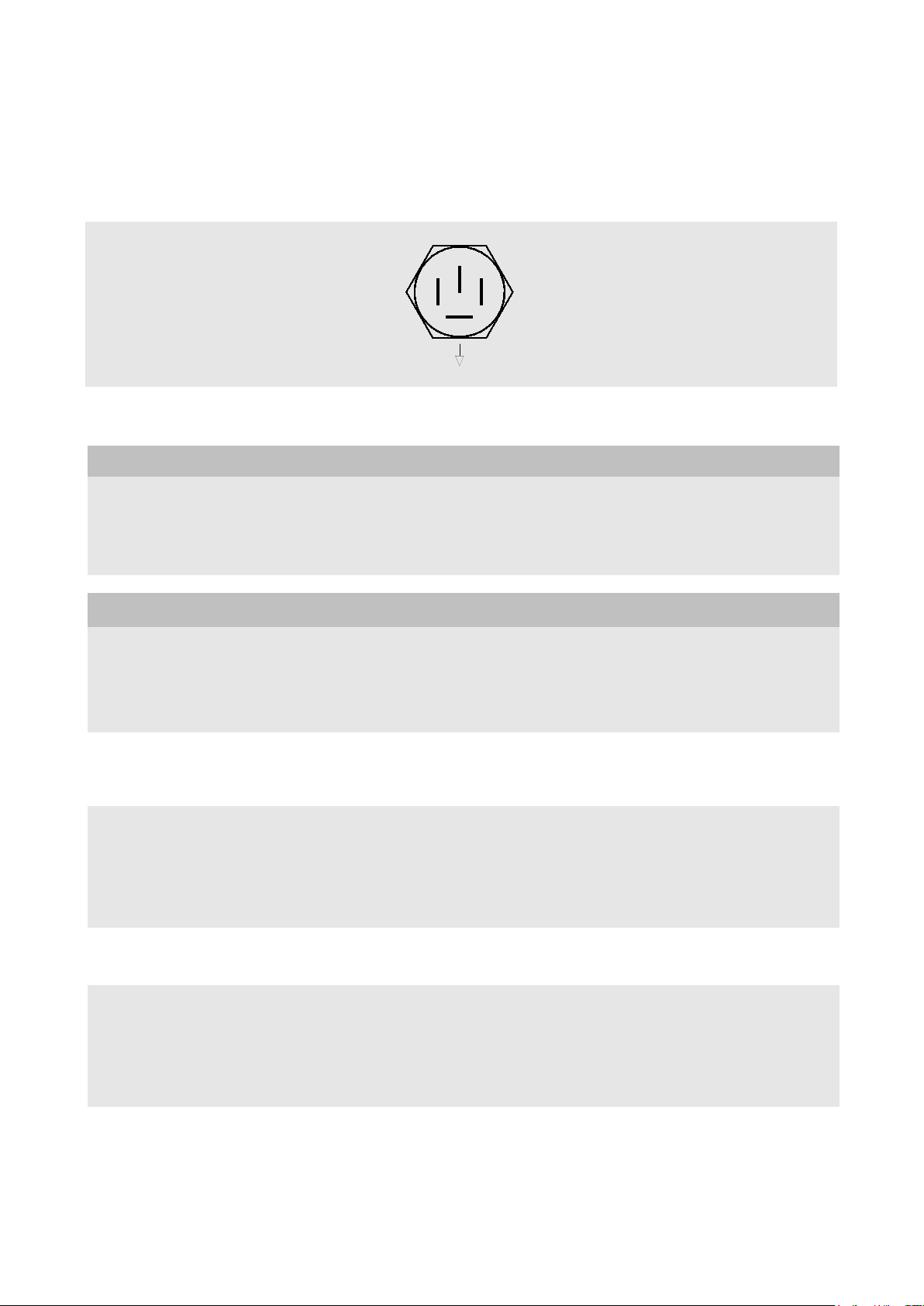
•Beim Anschließen auf richtige
Steckverbindung achten. Die
Anschlüsse sind am Sensor mit -
DC, COM, SIG, ↓gekennzeichnet.
(↓= 0 V)
•Ensure that the connections are
correct. The contacts are marked -
DC, COM, SIG, and „↓“ on the
accelerometer.
(↓= 0 V)
•
Przy podłączaniu trzeba uważać na
prawidłowe podłączenie wtyków.
Przyłącza na czujniku są
oznakowane -DC, COM, SIG, et
„↓“.
(↓= 0 V)

AS – 030
Seite/Page/Strona 9 von/of/z 11
© Brüel & Kjaer Vibro GmbH / 04.07.2017
C102787.001 / V05
Technische Änderungen vorbehalten!
Technical alterations reserved!
Zmiany techniczne zastrzeżone!
Anschluss
Connection
Przyłączenie
4 Faston Flachstecker 6,3 mm nach
DIN 46244
4 x Fast-on ferrule contacts 6.3 mm
according to DIN 46244
4 wtyki konektorowe Faston 6,3 mm
wg DIN 46244
AS030-4 (050816)
-DC
SIG
COM
Abb.
4 Anschluss
(Blick auf Steckkontakte)
Fig.
4 Connection diagram
(viewed from contact end)
Rys
. 4 Przyłącze
(widok styków wtykowych)
Hinweis
Note
Wskazówka
Für die Anschlüsse SIG und –DC
isolierte Flachstecker,
für COM und ↓nicht isolierte
Flachstecker verwenden!
For the contacts SIG and –DC insu-
lated Fast-
on ferrules should be used !
For the contacts COM and ↓non-
insulated Fast-on ferrules should be
used !
Do przyłączeń SIG i –DC stosujemy
izolowane wtyki konektorowe !
Do COM i ↓nieizolowane wtyki
konektorowe !
Achtung!
Caution!
Uwaga!
Bei Umgebungstemperaturen
> 80 °C muss das Sensorkabel
direkt an die Steckkontakte des
Sensors angelötet werden.
In case the ambient temperature is
higher than 80 °C, the sensor cable
must be soldered directly to the
plug contacts of the sensor instead
of using the supplied Fast-on
ferrules.
Przy temperaturach otoczenia
> 80 °C kabel czujnika musi być
przylutowany bezpośrednio do
styków wtykowych czujnika.
Sensorkabel an Steckkon-
takte des Sensors anlöten
Soldering the sensor cable
to the plug contacts of the
sensor
Przylutowanie kabla
czujnika do styków
wtykowych czujnika
Zum Anlöten darf die maximale
Löttemperatur 300°C nicht länger
als 10 Sek. An den Steckkontakten
anliegen. Eine Überhitzung der
Steckkontakte hat die Zerstörung
der Lötstellen innerhalbdes Sensors
zur Folge.
A soldering iron temperature of 300
deg. C must not be in contact with
the ferrule contacts for longer than
10 seconds, otherwise the soldered
contacts inside the accelerometer
will be loosened.
Lutując nie wolno utrzymywać na
stykach wtykowych maks.
temperatury lutowania 300°C dłużej
niż 10 sek. Przegrzanie styków
wtykowych prowadzi do zniszczenia
lutowin wewnątrz czujnika.
Nach dem Anschliessen ziehen Sie
die Schutzkappe auf den Sensor.
After the soldering is complete,
slide the protective cap over the
accelerometer.
Po przyłączeniu naciągamy nasadk
ę
ochronną na czujnik.
Das Oberteil der Schutzkappe
entsprechend dem Kabeldurch-
messer abschneiden und passende
Schlauchschelle verwenden.
Schlauchschelle am Kabelausgang
der Schutzkappe anbringen !
Cut the upper part of the protective
cap back to correspond with the
cable diame
ter and use the supplied
AC-305 hose clamp. This hose
clamp must be used at the point of
exit of the cable from the protective
cap!
Górną część nasadki ochronnej
przycinamy do średnicy kabla i
stosujemy pasujący zacisk
przewodu. Zacisk przewodu
umieszczamy na wyjściu kabla z
nasadki ochronnej !

AS – 030
© Brüel & Kjaer Vibro GmbH / 04.07.2017
C102787.016 / V05
Seite/Page/Strona 10 von/of/z 11
Technische Änderungen vorbehalten!
Technical alterations reserved!
Zmiany techniczne zastrzeżone!
38
ca.90
M8
SW 22
ø28
AS030-5 (050817)
5
Czujnik przyspieszenia
AS-030
Zacisk przewodu
(AC - 305)
Nasadka ochronna
(AC - 305)
Schutzkappe des Sensors:
Sensor protective cap:
Nasadka ochronna czujnika:
Zacisk przewodu
Zacisk przewodu
AC305-1 (050817)
ø2
ø3,21
ø5,45
ø8,59
SGL 7-11/5 ZYW2
(M/N 4374 336)
SGL 7-19/5 ZYW2
(M/N 4374 337)

AS – 030
Seite/Page/Strona 11 von/of/z 11
© Brüel & Kjaer Vibro GmbH / 04.07.2017
C102787.001 / V05
Technische Änderungen vorbehalten!
Technical alterations reserved!
Zmiany techniczne zastrzeżone!
Table of contents
Other Brüel & Kjaer Vibro Accessories manuals

Brüel & Kjaer Vibro
Brüel & Kjaer Vibro DS821 Series User manual

Brüel & Kjaer Vibro
Brüel & Kjaer Vibro DS821 Series User manual

Brüel & Kjaer Vibro
Brüel & Kjaer Vibro ds822 Series User manual

Brüel & Kjaer Vibro
Brüel & Kjaer Vibro AS-062/T1 User manual

Brüel & Kjaer Vibro
Brüel & Kjaer Vibro ASA-062 ATEX Series User manual
Popular Accessories manuals by other brands

PCB Piezotronics
PCB Piezotronics IMI SENSORS 640B06 Installation and operating manual

Dometic
Dometic MOBILE COOLING TROPICOOL TC07 operating manual

aci
aci SST2630 Installation & operation instructions

Vega
Vega VEGAPULS 66 Profibus PA Quick setup guide

Frederiksen
Frederiksen 251560 quick start guide

LEGRAND
LEGRAND 0 784 58 manual