ECS PMI8M User manual


Preface
i
Preface
Copyright
This publication, including all photographs, illustrations and software, is protected
under international copyright laws, with all rights reserved. Neither this manual, nor
any of the material contained herein, may be reproduced without written consent of
the author.
Version 2.0B
Disclaimer
The information in this document is subject to change without notice. The manufac-
turer makes no representations or warranties with respect to the contents hereof and
specifically disclaims any implied warranties of merchantability or fitness for any
particular purpose. The manufacturer reserves the right to revise this publication and
to make changes from time to time in the content hereof without obligation of the
manufacturer to notify any person of such revision or changes.
TrademarkRecognition
Microsoft, MS-DOS and Windows are registered trademarks of Microsoft Corp.
MMX, Pentium, Pentium-II, Pentium-III, Celeron are registered trademarks of Intel
Corporation.
Other product names used in this manual are the properties of their respective
owners and are acknowledged.
FederalCommunicationsCommission(FCC)
This equipment has been tested and found to comply with the limits for a Class B
digital device, pursuant to Part 15 of the FCC Rules. These limits are designed to
provide reasonable protection against harmful interference in a residential installa-
tion. This equipment generates, uses, and can radiate radio frequency energy and, if
not installed and used in accordance with the instructions, may cause harmful inter-
ference to radio communications. However, there is no guarantee that interference
will not occur in a particular installation. If this equipment does cause harmful
interference to radio or television reception, which can be determined by turning the
equipment off and on, the user is encouraged to try to correct the interference by one
or more of the following measures:
• Reorient or relocate the receiving antenna.
• Increase the separation between the equipment and the receiver.
• Connect the equipment onto an outlet on a circuit different from that to
which the receiver is connected.
• Consult the dealer or an experienced radio/TV technician for help.
Shielded interconnect cables and a shielded AC power cable must be employed with
this equipment to ensure compliance with the pertinent RF emission limits govern-
ing this device. Changes or modifications not expressly approved by the system’s
manufacturer could void the user’s authority to operate the equipment.

ii
Preface
DeclarationofConformity
This device complies with part 15 of the FCC rules. Operation is subject to the
following conditions:
• This device may not cause harmful interference, and
• This device must accept any interference received, including interference
that may cause undesired operation.
CanadianDepartmentofCommunications
This class B digital apparatus meets all requirements of the Canadian Interference-
causing Equipment Regulations.
Cet appareil numérique de la classe B respecte toutes les exigences du Réglement sur
le matériel brouilieur du Canada.
AbouttheManual
The manual consists of the following:
Chapter 1
Introducingthe Motherboard
Chapter 2
Installing the Motherboard
Chapter 3
UsingBIOS
Chapter 4
Using the Motherboard Soft-
ware
Describes features of the motherboard.
Go to Hpage 1
Describes installation of motherboard
components.
Provides information on using the BIOS
Setup Utility.
Describes the motherboard software
Goto Hpage 7
Go to Hpage 23
Go to Hpage 43

iii
TT
TT
TABLE OF CONTENTSABLE OF CONTENTS
ABLE OF CONTENTSABLE OF CONTENTS
ABLE OF CONTENTS
Preface i
Chapter 1 1
IntroducingtheMotherboard 1
Introduction................................................................................................1
Features.......................................................................................................2
MotherboardComponents.......................................................................4
Chapter 2 77
77
7
7
SafetyPrecautions....................................................................................7
Choosinga ComputerCase......................................................................7
Installingthe Motherboardin aCase.....................................................7
CheckingJumperSettings........................................................................8
Setting Jumpers............................................................................8
Checking Jumper Settings............................................................9
Jumper Settings............................................................................9
ConnectingCase Components...............................................................10
Front Panel Header.....................................................................11
InstallingHardware..................................................................................12
Installing the Processor...............................................................12
Installing Memory Modules.........................................................13
Installing a Hard Disk Drive/CD-ROM......................................14
Installing a Floppy Diskette Drive...............................................15
Installing Add-on Cards..............................................................16
Connecting Optional Devices......................................................18
ConnectingI/ODevices..........................................................................21
Chapter 3 2323
2323
23
UsingBIOS 23
Aboutthe SetupUtility...........................................................................23
The Standard Configuration.......................................................23
Entering the Setup Utility.............................................................23
Updating the BIOS......................................................................25
UsingBIOS................................................................................................25
Standard CMOS Features...........................................................26
Advanced BIOS Features............................................................28
InstallingtheMotherboard

iv
Integrated Peripherals.................................................................32
Power Management Setup...........................................................36
PNP/PCI Configurations.............................................................38
PC Health Status.........................................................................39
Frequency/Voltage Control..........................................................40
Load Fail-Safe Defaults................................................................41
Load Optimized Defaults.............................................................41
Set Supervisor/User Password....................................................41
Save & Exit Setup Option.............................................................42
Exit Without Saving......................................................................42
Chapter 4 4343
4343
43
UsingtheMotherboardSoftware 43
AbouttheSoftwareCD-ROM................................................................43
Auto-installingunderWindows 98/ME/2000/XP................................43
Running Setup..............................................................................44
ManualInstallation..................................................................................46
UtilitySoftwareReference.....................................................................46
Advanced Chipset Features.........................................................30

1
IntroducingtheMotherboard
Chapter1
IntroducingtheMotherboard
Introduction
Thank you for choosing PMI8M motherboard of great performance and with en-
hanced function. This motherboard carries an ITX form factor of 170 x 170 mm.
PMI8M supports Socket 479 Pentium M and Celeron processors with system bus
speeds up to 400MHz.
The motherboard may support 855GME/852GM Northbridges and ICH4M
Southbridge. 855GME/852GM Northbridge is a single processor with a data transfer
rate of 400 MHz, DDR-SDRAM at 333/266/200 MHz operation (852GM supports 266/200
MHz DDR SDRAM). It supports 128-Mb, 256-Mb and 512-Mb SDRAM technologies
providing maximum capacity of 1GB with X16 devices and up to 2GB with high
density 512-Mbit technology.
The ICH4M Southbridge on this motherboard supports one PCI slot which is PCI 2.2
compliant. It implements an EHCI compliant host controller that supports USB
high-speed signaling, integrates AC’97 v2.3 compliant controller that features a 6-
channel audio speaker out. It provides dual independent IDE channels support
UltraDMA 100/66/33.
There is an advanced full set of I/O ports in the rear panel, including PS/2 mouse and
keyboard connectors, three serial ports, VGA port, and four USB ports, two LAN
ports (LAN2 optional), and audio jacks for microphone and line-out.

2
IntroducingtheMotherboard
Features
Processor
This motherboard uses a 479-pin socket that carries the following features:
• Accommodates Intel Pentium M/Celeron processors
• Supports a system bus (FSB) of 400 MHz
Intel’s 855GME/852GM Northbridge (NB) and ICH4M Southbridge (SB) chipsets
are based on an innovative and scalable architecture with proven reliability and
performance.
855GME/
852GM(NB) • Supports DDR-SDRAM at 333/266/200MHz Operation
(852GM supports DDR266/200MHz only)
• Supports Host dynamic bus inversion (DBI)
• AGTL+bus driver technology with integrated AGTL termi-
nation resistors and low voltage operation
• Supports Internal Graphics Features with up to 64 MB of
Dynamic Video Memory allocation
Chipset
ICH4M(SB) • Compliant with PCI 2.2 specification at 33MHz
• Integrated LAN controller
• Supports AC’97 2.3 specification
• USB host interface supporting 6 USB ports; 3 UHCI host
controllersand 1 EHCIhigh-speedUSB 2.0 Host controller
• Supports up to two Ultra DMA100/66/33 IDE channels
• ACPI Power Management Logic support
Memory • Supports DDR 333/266 DDR SDRAM DIMMs (only 855GME
supports)
• Supports 128-Mb, 256-Mb and 512-Mb SDRAM technolo-
gies providing maximum capacity of 1GB with X16 de-
vices and up to 2GB with high density 512-Mbit technol-
ogy
• Video Stream Decoder, which supports for standard definition DVD
quality encoding at low CPU utilization
• Analog Display Support with 350 MHz integrated 24-bit RAMDAC
• High quality performance Texture Engine
Graphics
AC’97 Audio CODEC
• Compliant with theAC’97 v2.3 CODEC
• Supports 6-channel audio CODEC designed for PC multimedia sys-
tems
• Provides three analog line-level stereo inputs with 5-bit volume con-
trol: Line-in, CD,AUX
• Meets Microsoft WHQL/WLP 2.0 audio requirements
3
IntroducingtheMotherboard
Expansion Options
The motherboard comes with the following expansion options:
• One 32-bit PCI slot
• Two IDE connectors which support four IDE devices
• One floppy disk drive interface
• One CF socket (optional)
The motherboard supports Ultra DMA bus mastering with transfer rates of 100/66/
33MB/s.
Onboard LAN (Optional)
Some hardware specifications and software items are subject to change
without prior notice.
The motherboard has a full set of I/O ports and connectors:
• Two PS/2 ports for mouse and keyboard
• Three serial ports
• One VGA port
• Four USB ports
• Two LAN ports (LAN2 optional)
• Audio jacks for microphone and line-out
Integrated I/O
BIOS Firmware
This motherboard uses Award BIOS that enables users to configure many system
features including the following:
• Power management
• CPUparameters
• CPUandmemorytiming
The firmware can also be used to set parameters for different processor clock
speeds.
This motherboard may support either of the following LAN chipset:
• Supports 100/10 Mb/s N-Way Auto negotiation operation
• Half/Full duplex capability
• Supports Wake-On-LAN(WOL) function and remote wake-up
• Integrate 10/100/1000 transceiver
• Supports PCI v2.3, 32-bit, 33/66MHz
• Supportsfully with IEEE802.3, IEEE802.3uandIEEE802.3ab
4
IntroducingtheMotherboard
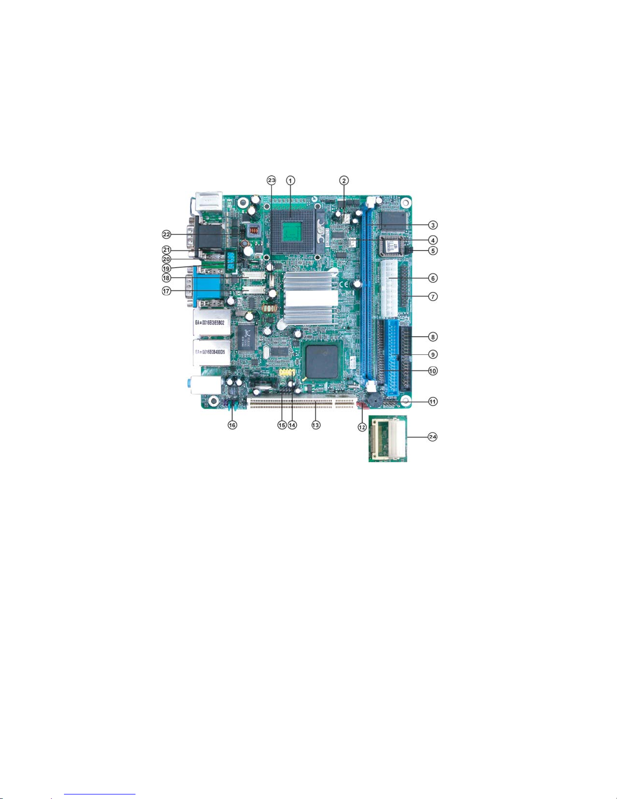
MotherboardComponents

5
IntroducingtheMotherboard
Table of Motherboard Components
“*” stands for optional components and may not exist onboard.
This concludes Chapter 1. The next chapter explains how to install the motherboard.
LABEL COMPONENTS
1. CPU Socket 479 socket for Pentium M/Celeron CPUs
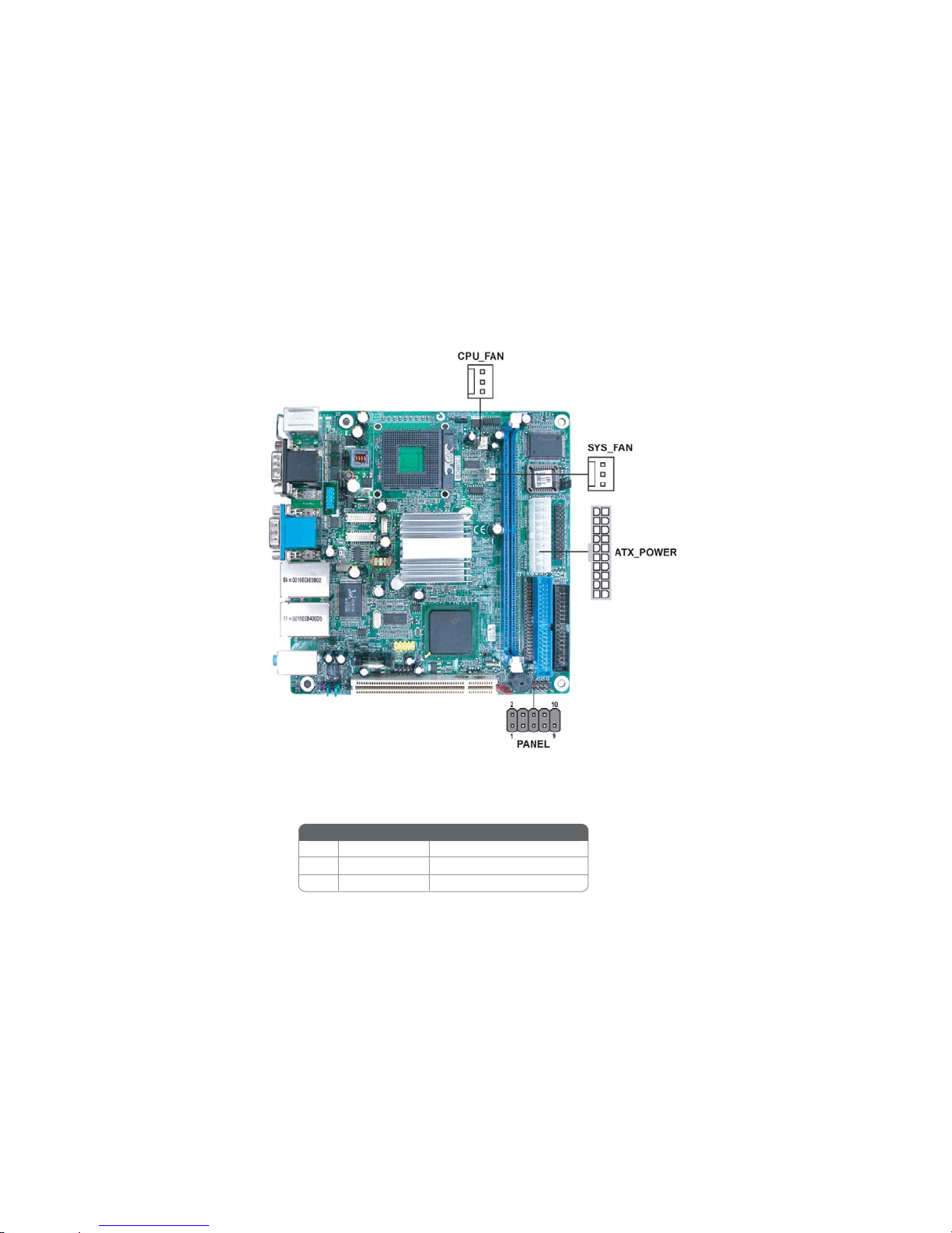
2. CPU_FAN CPUcooling fan connector
3. DIMM1 184-pin DDR SDRAM slot
4. SYS_FAN Systemcooling fan connector
5. CF_PWR* CF power voltage jumper
6. ATX_POWER Standard 20-pin ATX power connector
7. LPT LPT header
8. FDD Floppy diskdrive connector
9. IDE2 Secondary IDEconnector
10. IDE1 Primary IDEconnector
11. PANEL Front Panel switch/LED header
12. CLR_CMOS Clear CMOS jumper
13. PCI slot 32-bit add-on card slot
14. USB3 Front PanelUSBheader
15. DIO DIO port header
16. AUDIO Front panelAudio header
17. LVDS2 Low Voltage Differential Signaling Transmitter Interface Channel B
18. LVDS1 Low Voltage Differential Signaling Transmitter Interface Channel A
19. LVDS_PWR LowVoltage DifferentialSignaling Powerheader
20. COM4 Serial port header
21. JP2 COM3/COM4Ring function selector
22. JP1 COM1/COM2Ring function selector
23. LVDS3 LVDS power header
24. SCN1* C.F. Socket for installing C.F.(CompactFlash)card

6
IntroducingtheMotherboard
Memo

7
InstallingtheMotherboard
Chapter2
InstallingtheMotherboard
SafetyPrecautions
• Follow these safety precautions when installing the motherboard
• Wear a grounding strap attached to a grounded device to avoid dam-
age from static electricity
• Discharge static electricity by touching the metal case of a safely
grounded object before working on the motherboard
• Leave components in the static-proof bags they came in
• Hold all circuit boards by the edges. Do not bend circuit boards
Choosinga Computer Case
There are many types of computer cases on the market. The motherboard complies
with the specifications for the ITX system case. First, some features on the
motherboard are implemented by cabling connectors on the motherboard to indica-
tors and switches on the system case. Make sure that your case supports all the
features required. Secondly, this motherboard supports one or two floppy diskette
drives and four enhanced IDE drives. Make sure that your case has sufficient power
and space for all drives that you intend to install.
Most cases have a choice of I/O templates in the rear panel. Make sure that the I/O
template in the case matches the I/O ports installed on the rear edge of the
motherboard.
This motherboard carries an ITX form factor of 170 x 170 mm. Choose a case that
accommodates this form factor.
Installingthe Motherboard in a Case
Refer to the following illustration and instructions for installing the motherboard in
a case.
Most system cases have mounting brackets installed in the case, which correspond
the holes in the motherboard. Place the motherboard over the mounting brackets
and secure the motherboard onto the mounting brackets with screws.
Ensure that your case has an I/O template that supports the I/O ports and expansion
slots on your motherboard.

8
InstallingtheMotherboard
CheckingJumperSettings
This section explains how to set jumpers for correct configuration of the motherboard.
SettingJumpers
Use the motherboard jumpers to set system configuration options. Jumpers with
more than one pin are numbered. When setting the jumpers, ensure that the jumper
caps are placed on the correct pins.
The illustrations show a 2-pin jumper. When
the jumper cap is placed on both pins, the
jumper is SHORT. If you remove the jumper
cap, or place the jumper cap on just one pin,
the jumper is OPEN.
This illustration shows a 3-pin jumper. Pins
1 and 2 are SHORT.
SHORT OPEN
Do not over-tighten the screws as this can stress the motherboard.
9
InstallingtheMotherboard
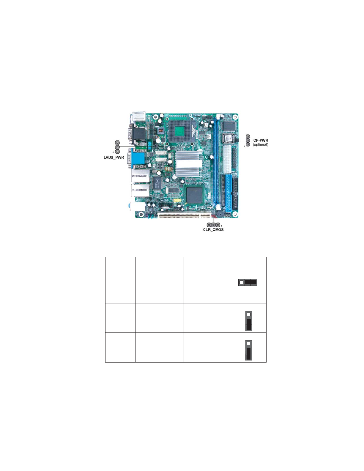
Checking Jumper Settings
The following illustration shows the location of the motherboard jumpers. Pin 1 is
labeled.
JumperSettings
Jumper Type Description Setting (default)
LVDS_PWR LVDS power
voltage 1-2: VCC3
2-3: VCC5
LVDS_PWR
CLR_CMOS 3-pin CLEAR CMOS 1-2: NORMAL
2-3: CLEAR CMOS
Before clearing the
CMOS, make sure to
turn the system off.
CLR_CMOS
1
CF_PWR
(optional)
CF power
voltage 1-2: VCC3
2-3: VCC5
CF_PWR (optional)
3-pin
1
3-pin
1
10
InstallingtheMotherboard
ConnectingCase Components
After you have installed the motherboard into a case, you can begin connecting the
motherboard components. Refer to the following:
1 Connect the CPU cooling fan cable to CPU_FAN.
2 Connect the system cooling fan connector to SYS_FAN.
3 Connect the case switches and indicator LEDs to the PANEL.
4 Connect the standard power supply connector to ATX_POWER.
CPU_FAN/SYS_FAN:FAN PowerConnectors
1 GND System Ground
2 +12V Power +12V
3 Sense Sensor
Pin Signal Name Function
11
InstallingtheMotherboard
Hard Drive Activity LED
Connecting pins 1 and 3 to a front panel mounted LED provides visual indication
that data is being read from or written to the hard drive. For the LED to function
properly, an IDE drive should be connected to the onboard IDE interface. The LED
will also show activity for devices connected to the SCSI (hard drive activity LED)
connector.
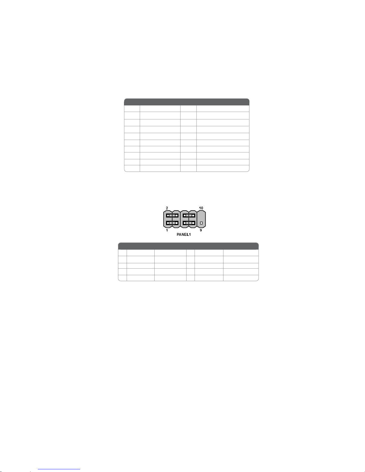
Front Panel Header
The front panel header (PANEL) provides a standard set of switch and LED headers
commonly found on ATX or micro-ATX cases. Refer to the table below for informa-
ATX_POWER: ATX 20-pin Power Connector
1VCC3 11 VCC3
2VCC3 12 -12V
10 +12V 20 VCC
3GND 13 GND
4VCC 14 PS-ON#
5GND 15 GND
6VCC 16 GND
7GND 17 GND
8PWROK 18 -5V
95VSB 19 VCC
Pin Signal Name Pin Signal Name
Pin Signal Name Function
1 HD_LED_P Hard Disk LED+ 2 FPPWR/SLP *MSG LED+
3 HD_LED_N Hard disk LED-
5 RST_SW_N Reset Switch
7 RST_SW_P Reset Switch
9 RSVD_DNU Reserved
4 FP PWR/SLP *MSG LED-
6 PWR_SW_P Power Switch
8 PWR_SW_N Power Switch
10 Key No pin
* MSG LED (dual color or single color)
Pin Signal Name Function

12
InstallingtheMotherboard
InstallingHardware
Installing the Processor
Before installing the Processor
This motherboard automatically determines the CPU clock frequency and system
bus frequency for the processor. You may be able to change these settings by making
changes to jumpers on the motherboard, or changing the settings in the system Setup
Utility. We strongly recommend that you do not over-clock processors or other
components to run faster than their rated speed.
This motherboard has a Socket 479 processor socket. When choosing a processor,
consider the performance requirements of the system. Performance is based on the
processor design, the clock speed and system bus frequency of the processor, and the
quantity of internal cache memory and external cache memory.
Reset Switch
Supporting the reset function requires connecting pin 5 and 7 to a momentary-
contact switch that is normally open. When the switch is closed, the board resets and
runs POST.
Power Switch
Supporting the power on/off function requires connecting pins 6 and 8 to a momen-
tary-contact switch that is normally open. The switch should maintain contact for at
least 50 ms to signal the power supply to switch on or off. The time requirement is
due to internal de-bounce circuitry. After receiving a power on/off signal, at least two
Caution: When installing a CPU heatsink and cooling fan make sure that
you DO NOT scratch the motherboard or any of the surface-mount
resistors with the clip of the cooling fan. If the clip of the cooling fan
scrapes across the motherboard, you may cause serious damage to the
motherboard or its components.
On most motherboards, there are small surface-mount resistors near the
processor socket, which may be damaged if the cooling fan is carelessly
installed.
Avoid using cooling fans with sharp edges on the fan casing and the
clips. Also, install the cooling fan in a well-lit work area so that you can
clearly see the motherboard and processor socket.
Warning: Over-clocking components can adversely affect the reliability of
the system and introduce errors into your system. Over-clocking can
permanently damage the motherboard by generating excess heat in
components that are run beyond the rated limits.
Power/Sleep/Message waiting LED
Connecting pins 2 and 4 to a single or dual-color, front panel mounted LED provides
power on/off, sleep, and message waiting indication.
13
InstallingtheMotherboard
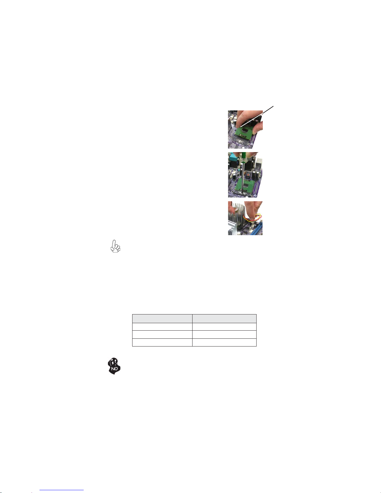
1 Install your CPU. Use a screwdriver to
make the CPU socket in tension release
position.
2 Locatethe CPU cut edge(thecorner with
the pin hold noticeably missing). Align
and insert the CPU correctly.
3 Use a screwdriver to screw up the CPU
socket.
4 Apply thermal grease on top of the CPU
5 Fasten the cooling fan supporting base
ontotheCPUsocketonthemotherboard.
6 Make sure the CPU fan is plugged to the
CPU fan connector. This completes the
installation.
CPU Installation Procedure
The following illustration shows CPU installation components.
To achieve better airflow rates and heat dissipation, we suggest that you use
a high quality fan with 6000 rpm at least. CPU fan and heatsink installation
procedures may vary with the type of CPU fan/heatsink supplied. The form
and size of fan/heatsink may also vary.
Do not remove any memory module from its antistatic packaging until you
are ready to install it on the motherboard. Handle the modules only by their
edges. Do not touch the components or metal parts. Always wear a ground-
ing strap when you handle the modules.
Installing Memory Modules
This motherboard accommodates one 184-pin unbuffered Double Data Rate (DDR)
SDRAM (Synchronous Dynamic Random Access Memory) memory module, and
supports DDR333/266/200 memory module (only when supports 855GME).
DDR SDRAM memory module table
Cut edge
DDR 333 166MHz
Memory module Memory Bus
DDR 266 133MHz
DDR 200 100MHz
14
InstallingtheMotherboard
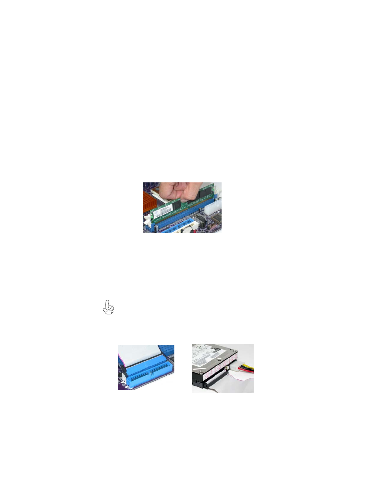
Installation Procedure
Refer to the following to install the memory modules.
1 This motherboard supports unbuffered DDR SDRAM only.
2 Push the latches on each side of the DIMM slot down.
3 Align the memory module with the slot. The DIMM slots are keyed with
notches and the DIMMs are keyed with cutouts so that they can only be
installed correctly.
4 Check that the cutouts on the DIMM module edge connector match the
notches in the DIMM slot.
5 Install the DIMM module into the slot and press it firmly down until it
seats correctly. The slot latches are levered upwards and latch on to
the edges of the DIMM.
6 Installany remaining DIMM modules.
Installing a Hard Disk Drive/CD-ROM
This section describes how to install IDE devices such as a hard disk drive and a CD-
ROM drive.
AboutIDE Devices
Your motherboard has a primary and secondary IDE channel interface (IDE1 and
IDE2). An IDE ribbon cable supporting two IDE devices is bundled with the
motherboard.
You must orient the cable connector so that the pin1 (color) edge of the
cable corresponds to the pin 1 of the I/O port connector.
IDE1: Primary IDE Connector
The first hard drive should always be connected to IDE1.
Table of contents
Other ECS Motherboard manuals


