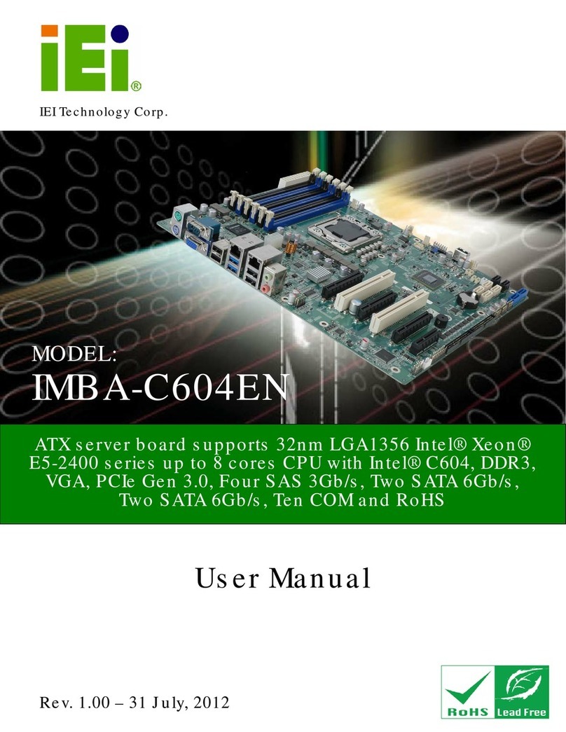
IMBA-XQ354 Motherboard
Page x
98H5.4.1 Clear CMOS Jumper........................................................................................ 569H77
99H5.4.2 COM Port Pin 9 Function Select..................................................................... 570H78
100H5.4.3 COM Port Pin 9 Voltage Setting Select ........................................................... 571H79
101H5.4.4 SPDIF Out Selection........................................................................................ 572H80
102H5.5 CHASSIS INSTALLATION............................................................................................ 573H82
103H5.5.1 Airflow.............................................................................................................. 574H82
104H5.5.2 IMBA-XQ354 Installation................................................................................ 575H82
105H5.5.3 Dual RS-232 Cable with Slot Bracket.............................................................. 576H82
106H5.5.4 Single RS-232 Cable with Slot Bracket............................................................ 577H83
107H5.5.5 SATA Drive Connection ................................................................................... 578H84
108H5.5.6 USB Cable (Dual Port) with Slot Bracket ....................................................... 579H86
109H5.5.7 USB Cable (Four Port).................................................................................... 580H87
110H5.6 EXTERNAL PERIPHERAL INTERFACE CONNECTION ................................................... 581H89
111H5.6.1 Keyboard and Mouse ....................................................................................... 582H89
112H5.6.2 LAN.................................................................................................................. 583H90
113H5.6.3 Parallel Device Connection............................................................................. 584H91
114H5.6.4 Serial Device.................................................................................................... 585H92
115H5.6.5 USB.................................................................................................................. 586H93
116H5.6.6 VGA Monitor.................................................................................................... 587H94
117H5.6.7 Audio Connector .............................................................................................. 588H95
118H6 BIOS SETUP................................................................................................................ 589H97
119H6.1 INTRODUCTION......................................................................................................... 590H98
120H6.1.1 Starting Setup................................................................................................... 591H98
121H6.1.2 Using Setup...................................................................................................... 592H98
122H6.1.3 Getting Help..................................................................................................... 593H99
123H6.1.4 Unable to Reboot After Configuration Changes.............................................. 594H99
124H6.1.5 BIOS Menu Bar................................................................................................ 595H99
125H6.2 MAIN...................................................................................................................... 596H100
126H6.3ADVANCED............................................................................................................. 597H101
127H6.3.1 CPU Configuration........................................................................................ 598H103
128H6.3.2 IDE Configuration......................................................................................... 599H104
129H6.3.2.1 IDE Master, IDE Slave ........................................................................... 600H106
130H6.3.3 Floppy Configuration......................................................................................601H111
131H6.3.4 Super IO Configuration ..................................................................................602H112
