AIRLESSCO Premium Series User manual

Premium Series
Professional
Pressure Washers
Service/Operation
Manual
Form No. 001-612 APR2605

WWW.AIRLESSCO.COM TEL: 805-523-0211 FAX: 805-523-1063
Manufactured by: AIRLESSCO BY DUROTECH CO.
P.O. Box 8006, Moorpark, CA 93020-8006 Ship to: 5397 Commerce Ave., Moorpark, CA 93021
Tel: 805-523-0211 Fax: 805-523-1063 SUBJECT TO CHANGE WITHOUT NOTICE.
Copyright © 2005, Airlessco by Durotech. All rights reserved.
For Technical Assistance:
Tel: 805-523-0211 Option 3
Email: [email protected]
For Customer Service/Order Desk:
Tel: 805-523-0211 Option 2
Email: [email protected]

WWW.AIRLESSCO.COM TEL: 805-523-0211 FAX: 805-523-1063
Email: [email protected]
TABLE OF CONTENTS
Manufactured by: AIRLESSCO BY DUROTECH CO.
P.O. Box 8006, Moorpark, CA 93020-8006 Ship to: 5397 Commerce Ave., Moorpark, CA 93021
Tel: 805-523-0211 Fax: 805-523-1063 SUBJECT TO CHANGE WITHOUT NOTICE.
Copyright © 2005, Airlessco by Durotech. All rights reserved.
Introduction
Pressure Washer Specications 1
Safety Warnings 2
Getting Started
Parts 4
Users Guide 5
Get The Most From Your Machine 6
Repairs/Maintenance Instructions
Tips and Nozzles 7
Cleaning Nozzle Rating Chart 8
Troubleshooting 9
Pump Servicing Procedure 10
Application & Installation of
the Unloader Valve 21
Troubleshooting - Unloader Valve 21
Downstream Chemical Injectors 31
Sandblast Kit 32
Sandblasting Application 33
Troubleshooting - Sandblast Kit 33
Limited Warranty 34
Accessories back cover
Product Diagrams & Parts List
Specications - Model 1500-3 11
Dimensional Drawing - Model 1500-3 11
Parts Breakdown - Model 1500-3 12
Specications - Model 2500-3 13
Dimensional Drawing - Model 2500-3 13
Parts Breakdown - Model 2500-3 14
Specications - Model 2500-5 15
Dimensional Drawing - Model 2500-5 15
Parts Breakdown - Model 2500-5 16
Specications - Model 3000-4 17
Dimensional Drawing - Model 3000-4 17
Parts Breakdown - Model 3000-4 18
Specications - Model 4000-3.5 19
Dimensional Drawing - Model 4000-3.5 19
Parts Breakdown - Model 4000-3.5 20
Specications & Breakdown for
Unloader Valve YVB135KDM 22
Specications & Breakdown for
Unloader Valve YVB75KDMN 23
Frame Assembly Part No. 163-055 24
Frame Assembly Part No. 163-024 25
Pump Assembly - Model 1500-3 26
Pump Assembly - Model 2500-3 27
Pump Assembly - Model 2500-5 28
Pump Assembly - Model 3000-4 29
Pump Assembly - Model 4000-3.5 30
Before operating this unit, read and follow all safety warnings and instructions
related to the usage of this equipment.
HANDLE THIS UNIT AS YOU WOULD A LOADED FIREARM!!
High pressure spray can cause extremely serious injury.
OBSERVE ALL WARNINGS!
For Customer Service/Order Desk:
Tel: 805-523-0211 Option 2
Email: [email protected]

WWW.AIRLESSCO.COM TEL: 805-523-0211 FAX: 805-523-1063
Email: [email protected]
WWW.AIRLESSCO.COM TEL: 805-523-0211 FAX: 805-523-1063
All pumps come standard with Honda Engine, General Pump,
Chemical Injector, 5 Color Coded Cleaning Nozzles, 50’ hose, gun
PRESSURE TO SUCCEED
Direct Drive - No Belts
• More compact design
• No belt adjustment required
• No slippage of belts
• No bulky belt guard
Premium Series - Cold Water High Performance
Pressure Washers Specications
Model
1500-3
2500-3
3000-4
2500-5
4000-3.5
P.N.
163-060
163-061
163-063
163-062
163-064
HP
4
5.5
11
11
11
GPM
2.80
2.88
4.0
4.6
3.5
PSI
1500
2500
3000
3000
4000
Hose Rack and
Gun Hook
Honda Engine with oil alert
Engine Protector
50’ x 3/8” High Pressure Hose
with Quick Couplers
General Pump - Ceramic
Plunger-3 Plex
• Best Warranty
• All easily accessible pump components
Modular Unloader Valve
Chemical Injector
Color Coded Cleaning Nozzles
Convenient Tip Holder on
the Frame
Durable Chrome Steel
Tubular Frame
Thermal Protector and Safety
Pressure Relief Valve 13” Turf Saver Pneumatic Tires
• Easier to roll
• Shock absorbing capability
*Picture shown is Model 4000-3.5
1

WWW.AIRLESSCO.COM TEL: 805-523-0211 FAX: 805-523-1063
Email: [email protected]
WARNINGS
HIGH PRESSURE SPRAY CAN CAUSE EXTREMELY SERIOUS INJURY.
NEVER PUT YOUR HAND OR FINGERS IN FRONT OF GUN.
NEVER POINT THE GUN AT YOUR BODY OR AT ANYONE ELSE.
• Always shut off the pump and relieve uid pressure in system by opening control handle if unit is left
unattended or before removing or installing accessories.
• When control handle is not in use, engage trigger safety to prevent accidental spraying.
• Do not allow kinks to form in hose between pump and control handle as this will reduce safety factor.
• Always wear face shield, eye goggles, gloves and protective clothing, so spray containing chemicals do not
contact eyes, ears, nose or skin. If chemicals do contact skin or eyes, ush immediately with large amounts
of water and seek medical attention.
Do not run the engine in
an enclosed area. Exhaust gases
contain carbon monoxide, an odorless
and deadly poison.
Do not run engine at excessive speed.
Excessive speeds increase
the danger of personal injury and
voids warranty.
A FIRE OR EXPLOSION CAN OCCUR RESULTING IN PERSONAL INJURY IF THE
FOLLOWING INSTRUCTIONS ARE NOT FOLLOWED:
• DO NOT FILL GASOLINE TANK while engine is
running. Allow engine to cool before refueling.
• Do not operate the engine when an odor of gasoline is
present or other explosive conditions exist.
• If gasoline is spilled, move machine away from the
area of the spill and avoid creating any source of
ignition until the gasoline has been cleaned up.
• Do not store, spill or use gasoline near an open ame
or devices that utilizes a pilot light or which may
cause a spark such as a stove, furnace or water heater.
• Refuel outdoors or in well ventilated areas only.
• DO NOT operate engine without a mufer. Inspect
mufer periodically and replace as necessary. Clean
mufer area to prevent dirt and combustible material
from accumulating.
• Exhaust fumes are poisonous. Do not operate except
in open and well ventilated areas.
• Do not operate the engine if air cleaner or cover
directly over the carburetor air intake is removed.
• Do not choke carburetor to stop engine.
• Do not tamper with the engine speed.
• Do not touch hot mufer, cylinders or ns as contact
may cause burns.
• Dirt or other debris in cooling ns or governor parts,
can affect engine speed.
• To prevent hand or arm injury, always pull starter
cord rapidly to avoid kickback.
• To prevent accidental starting when servicing, always
remove spark plug and insert in holding tab & discon-
nect negative wire from battery terminal if equipped
with a 12 volt starting system.
NOTE: Shutting off power by itself may not relieve uid pressure.
2

WWW.AIRLESSCO.COM TEL: 805-523-0211 FAX: 805-523-1063
Email: [email protected]
WWW.AIRLESSCO.COM TEL: 805-523-0211 FAX: 805-523-1063
ALWAYS:
• Always remember that liquid released at pressure can penetrate skin, causing SERIOUS injury.
If injury occurs, seek immediate medical attention.
• Always follow all instructions and recommendations when operating equipment.
• Always protect high pressure hose from damage such as from vehicle trafc and sharp edges.
• Always wear protective clothing, gloves and goggles when using any potentially harmful chemicals.
• Always lock gun jet off when removing or changing nozzle.
• Always insure nozzle is secure in coupler before using. Improper installation may cause serious
injury or other damage. Test by aiming nozzle at ground prior to use.
• Always insure that water supply is adequate to supply pump. Water supply must deliver 3.5 gallons
per minute.
• Always inspect unit, hoses and ttings prior to use.
NEVER:
• Never place hand or any other part of the body in front of spray orice.
• Never direct spray at self or any other person.
• Never pump any acid or abrasive uid.
• Never wash electrical equipment or parts.
• Never attempt to repair a damaged high-pressure hose.
• Never allow unit to run more than ve minutes without operating gun jet. Water in pump will
overheat sufciently to damage pump. An optional high temperature sensor is available for this
unit from Airlessco.
WHILE OPERATING MAINTAIN SUFFICIENT LEVELS OF:
• Fuel - Any fuel intended for automotive use is adequate. Unleaded fuel is recommended to reduce
combustion deposits.
• Engine Oil - See engine manual for checking procedure and recommended oil grade.
• Gearbox Oil - Check through sight window on side of gearbox. Replenish with 90 wt. gear oil.
• Pump Oil - Check through sight window on side of pump. Replenish with SAE 20/ 30 oil.
WARNINGS
3

WWW.AIRLESSCO.COM TEL: 805-523-0211 FAX: 805-523-1063
Email: [email protected]
HIGH PRESSURE HOSE
• The hose provided by AIRLESSCO is selected from the nest hoses available and is intended to be used on your
machine only.
• DO NOT use pressure hose for any other purpose & do not substitute any other hoses for high pressure hose.
• If the hose becomes frayed or has any cuts on it, the hose must be replaced.
• Do not allow your pressure hoses to be run over by any type of vehicle.
SPRAY GUN- OR CONTROL HANDLE
• The gun included with your machine should always be treated as a loaded rearm.
• HIGH PRESSURE WATER IS DANGEROUS & should never be directed at any person or any body parts.
• Your gun has safety features you should use. The Trigger Lock should be engaged any time gun is not in use.
• DO NOT TAPE OR TIE, in any way render the spring device inoperative.
WAND
• The wand supplied with your machine should be handled with care. If the wand is bent it should be replaced.
CHEMICAL INJECTOR
• Your machine is equipped to use a CHEMICAL INJECTOR for those jobs that require more than water cleaning.
The AIRLESSCO CHEMICAL INJECTOR will allow you to soak the surface with a liquid chemical/detergent.
• If you need to use surface conditioners such as soaps and degreasers, you must use a CHEMICAL INJECTOR.
• DO NOT pump any surface conditions or any other medium other than water through the high pressure pump.
To do so could damage the pump and void your warranty.
SAND INJECTOR - OPTIONAL ITEM
• AIRLESSCO units are equipped to use a SAND INJECTOR SYSTEM. Water Sandblasting is an extremely
effective way of cleaning. The AIRLESSCO SAND BLASTING INJECTOR allows sand to ow into the high
pressure water stream to create a powerful cleaning system. Dry sandblasting is being replaced by wet
sandblasting. SOME USES: Removing boat barnacles, rust, grafti and blasting painted surfaces down to metal
for repainting.
PARTS
INLET WATER FILTER
• The inlet water screen is intended to prevent debris from entering the pump and causing damage. DO NOT
OPERATE the machine without the Inlet Water Screen in place.
• The Inlet Water Screen is stainless steel and should be removed and cleaned every 25 hours of operation. If
your water conditions are poorer than normal, it should be cleaned more often.
4

WWW.AIRLESSCO.COM TEL: 805-523-0211 FAX: 805-523-1063
Email: [email protected]
WWW.AIRLESSCO.COM TEL: 805-523-0211 FAX: 805-523-1063
Prior to Starting:
• Read and understand all warnings before operating euipment.
• Connect standard garden hose to water inlet. Hose must have minimum 5/8 inch diameter. Maximum 50 Ft.
length is recommended. Water source must deliver 3.5 gallons per minute either through pressurized system
of public utility or similar system or through gravity feed from unpressurized holding tank. Never allow
pump to run dry or semi-dry.
• Connect high pressure hose, gunjet, wand assembly to high pressure outlet. Failure to properly lock quick
coupler sleeve may result in “blow-out” and loss of quick coupler O-ring.
• Turn water supply fully on.
• Open fuel valve on engine. Turn ignition switch on (if so equipped). Set choke and throttle controls.
• Operate control handle (gun) by squeezing trigger and hold until continuous ow of water emerges.
• Turn pressure adjustment knob fully counterclockwise.
3. Cover outdoor light and electrical xtures with plastic bags.
4. Protect ush receptacles with plastic tape. Be sure they are watertight.
5. Note location of vent openings. (Eaves & crawl spaces often have vent openings). Do not spray into these
openings.
6. Protect landscape with plastic covers. This helps in clean up.
(Especially helpful when using chemicals and when blasting off paint).
7. General washing technique is started from the highest point. When working from a ladder make sure it is
sturdy and position the ladder so you are spraying away from yourself. Never spray directly overhead. Be
prepared for the initial “kick” that is caused by the high pressure spray.
8. Start ushing debris out of gutters. Use a 15 degree nozzle about 3 feet away.
9. Wash underhang portion of soft throughly, spraying from a distance of 12" to 18".
10. When cleaning the sides of your house work from the top to the bottom using overlapping strokes. If using
chemicals or soap apply solution from bottom to top and then rinse from the top to the bottom.
11. When cleaning around windows, approach it cautiously. If panes are not secure or not well caulked they can
break from the impact of the high pressure spray. Use a wider nozzle, start from a distance and approach
cautiously.
PREPARATION INSTRUCTIONS BEFORE WASHING OR REPAINTING YOUR HOSE
1. Please read all safety warnings.
2. If walls are badly stained, mildewed or soiled, detergents and the Airlessco Chemical Injector are recommended.
A strong cleanser or tri-sodium phosphate works well to remove stains. Bleaches help to kill mildew.
USERS GUIDE
USING THE AIRLESSCO CHEMICAL INJECTOR
●The chemical injector will draw the detergent. It is adjustable for the required ratio.
●Wash from the BOTTOM to the TOP so the solution is continually being rewetted and
allows the chemical to work.
●Rinse from the TOP to the BOTTOM before the chemical dries.
5

WWW.AIRLESSCO.COM TEL: 805-523-0211 FAX: 805-523-1063
Email: [email protected]
• Always consider which way the wind is blowing to
avoid overspraying.
• Spray surface conditioners so you are “Up Wind”.
• Never allow surface conditioners, soap or other chemi-
cals to get on vegetation. Use plastic sheeting to protect.
• Keep the quick couplers out of dirt and sand. If they
should have dirt or other debris on them, clean the quick
coupler thoroughly before using.
• Do not allow your hand or body to come in contact with
water spray. HANDLE AS YOU WOULD A LOADED
FIREARM!!
REMEMBER, although prepertion is hard work it will mean extra years of good
protection and good looks.
0º For Power Blasting - Delivers very concentrated stream of water. Exercise caution as the
impact force can damage soft surfaces.
15º For Chiseling & Stripping Action - Quickly removes blistered and peeling paint or other
residues. Spray should be directed at 45° angle.
25° For Power Cleaning & Flushing - The perfect wider spray angle for effectively washing
away dirt, mud and grime.
40º For Moderate Washing & Rinsing - Its wide spray pattern “sweeps” surfaces clean.
• Select the right tip for the job.
• Never allow anyone into your work area & risk injury.
• Approach target from a slight angle (“sweep” surface).
• Always wear face shield and eye protection.
• Turn machine off and relieve pressure from hose &
system before disconnecting hoses, control handle
(gun) or tips.
• Cover any exposed electrical sockets, plugs, lights or
other exposed electrical connections.
• Do not kink the high pressure hose, the wires inside
may bend and become weak or break.
GET THE MOST FROM YOUR MACHINE
To Operate Unit:
1. Select desired nozzle. Lock control handle (gun or
wand) off and install nozzle in quick coupler
at end of wand. Insure that coupler sleeve is
properly locked by pulling on nozzle.
2. Start engine according to engine manual.
3. Unlock control handle (gun or wand), point
wand at ground and operate to test.
4. Adjust pressure of spray to desired level.To Use
Chemical Injector:
1. Push end of chemical pick-up tube onto injector inlet.
2. Place lter end of pick-up tube in container of chemical
to be dispensed. Unit mixes chemical with water.
Ratio is adjustable.
3. Attach proper nozzle to wand. (Injector will draw
chemical only with special large orice, fan pattern
nozzle supplied).
4. Operate control handle as usual.
5. After use, remove nozzle from wand and place pick-up
tube lter end in container of water. Flush out tube by
operating gunjet.
TO REMOVE PEELING PAINT:
1. Start at the highest point. Use a 15 degree nozzle.
2. Spray should be directed 4"-12" from the surface at an angle of 45 degrees. This will allow you to work the
spray like a chisel.
3. On the soft, peel at a parallel angle. It will peel off in large sheets if you can get beneath it.
4. Spray in a back & forth motion always trying to get beneath the peeling paint. Be sure to get as much paint off as
possible & don’t be concerned about the paint that remains, it is bonded well enough to not cause a problem.
5. If paint edges curl up after being pressure washed, use a scraper or steel brush on these areas.
6. Remove loose putty around windows.
7. Spot prime any bare wood areas. When primer has dried apply putty and caulking as necessary.
USERS GUIDE
6

WWW.AIRLESSCO.COM TEL: 805-523-0211 FAX: 805-523-1063
Email: [email protected]
WWW.AIRLESSCO.COM TEL: 805-523-0211 FAX: 805-523-1063
TIPS OR NOZZLES
The Quick Couplet Tips or Nozzles are inserted into the
end of the wand by means of a Quick Coupler. Tips are
supplied in the four most popular sizes & can do many
jobs for you. You MUST seat the tip into the quick coupler
rmly and make sure the quick coupler is closed. If you
have a leak at the tip around the quick coupler, you have
lost the O-Ring inside the quick coupler. If lost, the O-Ring
MUST BE REPLACED!
Failure to lock the quick coupler into place can result in
personal injury and loss of the O-Ring on a female coupler.
Danger signals are indicated by water leakage.
Learning what each tip can do for you will make your
AIRLESSCO machine more valuable and will allow you
to do your cleaning jobs faster and more effectively. By
experimenting, you will nd that different tips do the job
better and moving the wand closer to and farther from the
area to be cleaned will also change the way the machine
will work for you.
You should always start each new job away from the target
and move closer as you see the need. Be careful, you can
damage some surfaces if the pressure is too concentrated
and too close.
NOZZLE SELECTION GUIDE
The pressure and volume of a pressure washer is deter-
mined by the size of the opening (orice) in the nozzle.
There are numbers on the nozzle which explain it’s size.
The rst two numbers indicate the size of the spray angle.
(00 means 0 degree, 15 means 15 degrees etc…) The last
number indicates the size of the orice. This is not a mea-
surement of an inch, but a standardized measurement.
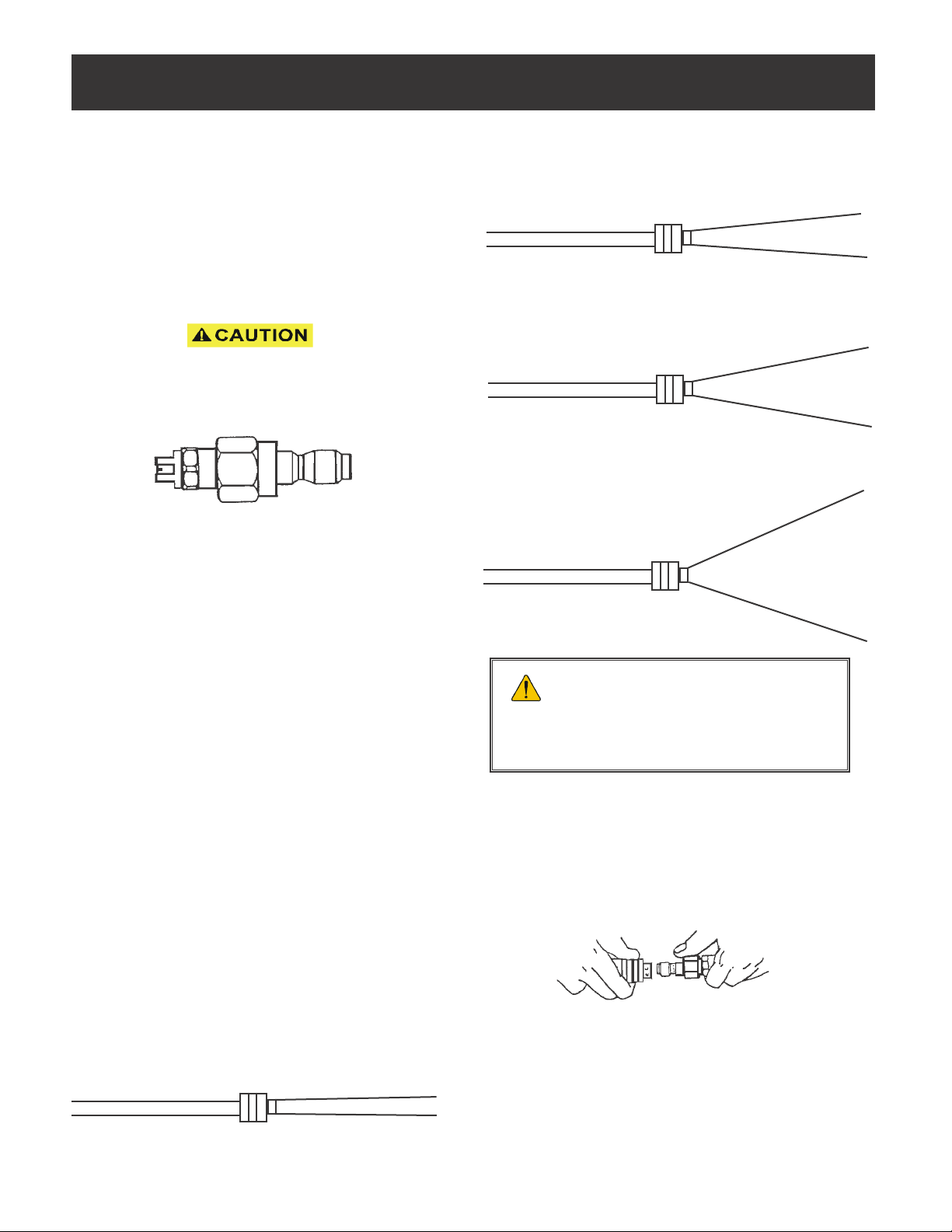
THE 0 DEGREE NOZZLE –
This is the blasting nozzle. It delivers a very concentrated
stream of water. Care should be used to avoid damaging
wood or fragile surfaces. WARNING: This nozzle must
not be used on rental machines supplied to homeowners or
non-contractors.
TIPS AND NOZZLES
THE 15 DEGREE NOZZLE – 3/4"
This is a chiseling nozzle. The spray should be directed at a
45 degree angle to the surface and used like a scraper to re-
move paint, grease and dirt. This is the most used tip of all.
THE 25 DEGREE NOZZLE – 5-6”
This is a ushing nozzle. It gives a wider coverage and is
used if the area being cleaned would be damaged by a nar-
rower tip.
THE 40 DEGREE NOZZLE – 8-10” –
This is a wash nozzle. Its wide spray pattern disperses the
water pressure over a large area and is recommended
for rinsing and moderate washing.
TIPS WILL WEAR IN TIME. THE MORE
YOU USE A TIP, THE MORE YOUR TIP
WILL WEAR. A WORN TIP WILL CAUSE A
SIGNIFICANT DROP IN PRESSURE. CHECK
AND REPLACE YOUR TIPS FREQUENTLY.
QUICK COUPLER
The quick coupler allows you to attach different devices to-
gether quick and secure. To use, simply slide the collar back
and insert the plug. Make sure the plug is securely seated.
It’s always a good idea to “tug” on the two parts to make
sure they are rmly seated together.
Always make sure the O-Ring is in place inside the quick
coupler. To see if the O-Ring is in place, make sure the Pres-
sure Washer is off and all system pressure has been relieved,
then you may look into the quick coupler at the collar (fe-
male) side of the quick coupler. You will be able to see the
O-Ring inside. If the O-Ring is missing, it must be replaced
to ensure a good pressure seal.
0°
15°
25°
40°
Socket Plug
7

WWW.AIRLESSCO.COM TEL: 805-523-0211 FAX: 805-523-1063
Email: [email protected]
CLEANING NOZZLE RATING CHART
The chart below provides gallons per minute for a 0˚ cleaning nozzle used on different PSI (pounds
per square inch) pressure washers. For example, a 2000 PSI pressure washer with a 0˚ No. 4.5 cleaning
nozzle will produce 3.1 gallons per minute. This chart can also assist in determining the proper nozzle
size for a particular pressure washer if the operating pressure and gallons per minute rating are known.
For example: a pressure washer rated at 3000 PSI @ 3.5 GPM, would require a No. 4 cleaning nozzle.
NOTE: The proper nozzle size for each pressure washer
can be found on the machine specication plate (located on the frame).
Orice Size 1000 1500 2000 2500 3000 3500 4000 5000
3.0 1.8 2.1 2.4 2.6 2.8 2.8 3.35
4.0 2.0 2.4 2.8 3.1 3.5 3.7 4.0 4.5
4.5 2.2 2.7 3.1 3.5 3.8 4.2 4.5 5.0
5.0 2.5 3.1 3.5 3.9 4.3 4.7 5.0 5.6
5.5 2.8 3.4 3.9 4.3 4.8 5.1 5.5 6.2
6.0 3.0 3.7 4.2 4.7 5.2 5.6 6.0 6.7
6.5 3.3 4.0 4.6 5.1 5.6 6.1 6.5 7.3
7.0 3.5 4.3 4.9 5.5 6.1 6.6 7.0 7.8
7.5 3.8 4.6 5.3 5.9 6.5 7.0 7.5 8.4
8.0 4.0 4.9 5.7 6.3 6.9 7.4 8.0 8.9
8.5 4.3 5.2 6.0 6.7 7.4 8.0 8.5 9.5
9.0 4.5 5.5 6.4 7.1 7.8 8.4 9.0 10.1
8
Nozzle PSI

WWW.AIRLESSCO.COM TEL: 805-523-0211 FAX: 805-523-1063
Email: [email protected]
WWW.AIRLESSCO.COM TEL: 805-523-0211 FAX: 805-523-1063
TROUBLE SHOOTING
PROBLEM CAUSE REMEDY
Low Pressure
• Worn nozzle
• Air leak in inlet plumbing
• Relief valve stuck, partially
plugged or improperly adjusted
valve seat worn
• Inlet suction strainer clogged or
improperly sized
• Worn packing; Abrasives in
pumped uid or severe cavitation;
Inadequate water
• Fouled or dirty inlet or discharge
valves. Leaky discharge hose
• Disassemble, reseal and reassemble
• Clean, adjust relief valve; check for
worn and dirty valve seats
• Clean, use adequate size; check more
frequently
• Install proper lter, suction at manifold
must be limited to lifting less than 20
feet of water or -8.5 PSI vacuum.
• Clean inlet and discharge valve assemblies
• Replace worn valves, valve seats and/
or discharge hose
Pump runs extremely
rough, pressure very
low
• Restricted inlet or air entering the
inlet plumbing
• Inlet restrictions and/or air leaks;
Stuck inlet or discharge valve
• Proper size inlet plumbing; check for air
tight seal.
• Replace worn cup or cups; clean out
foreign material, replace worn valve
Water leakage from
under manifold; Slight
leakage
• Worn packing
• Install new packing
Oil leak between
crankcase and
pumping section
• Replace crankcase piston rod seals;
Replace O-rings
Excessive play in the
end of the crankshaft
pulley
• Worn crankcase, piston rod
seals O-ring on plunger
Oil leaking in the area
of crankshaft
• Worn crankshaft seal or improperly
installed oil seal O-ring
• Bad bearing
• Remove oil seal and replace damaged
O-ring and/ or seals
• Replace bearing
• Worn main bearing form
excessive tension on drive belt
• Replace crankcase bearing and/or tension
drive belt
Water in crankcase
• May be caused by humid air
condensing into water inside the
crankcase
• Worn packing and/or piston rod
sleeve, & O-rings on plunger retainer
• Change oil intervals; use any high grade
automotive 30 weight non detergent oil
• Replace packing, replace O-rings
Oil leaking from un-
derside of crankcase
• Worn crankcase piston rod seals • Replace seals
• Damaged crankcase, rear cover
O-ring, drain plug O-ring or slight
glass O-ring
• Replace specic O-ring
Oil leaking at the rear
portion of the
crankcase
Loud knocking noise
in pump
Frequent or premature
failure of the packing
• Pulley loose on crankshaft
• Broken or worn bearing
• Check key and tighten set screw
• Replace bearing
• Scored, damaged or worn plunger
• Overpressure to inlet manifold
• Abrasive material in the uid being
pumped
• Excessive pressure and/or
temperature of uid being pumped
• Over pressure of pumps
• Running pump dry
• Replace plungers
• Reduce inlet pressure
• Install proper ltration on pump inlet
plumbing
• Check pressure and uid inlet temperature;
be sure they are with in specied range.
• Reduce pressure
• Do not run pump without water
9

WWW.AIRLESSCO.COM TEL: 805-523-0211 FAX: 805-523-1063
Email: [email protected]
PUMP SERVICING PROCEDURE
When sliding head from crankcase use
caution not to damage plungers.
10
Valve Assemblies
1. All inlet and discharge valves can be serviced without
disrupting the inlet discharge plumbing. The inlet and
discharge valves are the identical in all models.
2. To service any valve, remove valve cap and extract
valve assembly.
3. Examine O-rings and replace if there is any evidence
of cuts, abrasions, or distortion.
4. Remove valve assembly (retainer, spring, valve,
valve seat) from valve cavity.
5. Remove O-ring from valve cavity.
6. Only one valve kit is necessary to repair all the valves
in the pump. The kit includes new O-rings, valve
seat, poppet, spring and retainer, all pre-assembled.
7. Install new O-ring in valve cavity.
8. Insert assembly into valve cavity.
9. Replace valve cap and torque to specications.
Removing Manifold Head
1. Remove the fasteners retaining head.
2. Separate head from crankcase.
Note: It may be neccessary to tap the head lightly
with a rawhide mallet to loosen.
3. The V-packing assemblies may come off with the
head. At this point, examine plungers. Plunger
surfaces should be smooth and free from scoring or
pitting; if not, replace.
4. Reinstall manifold head and torque to specications
per sequence described below.
Torque Sequence For Tightening Head
Install all head bolts nger tight. Torque to 10 foot
pounds in sequence as shown below, then retorque to
specications again in sequence.
Replacing Plungers
1. Remove stainless steel piston screw and plunger
from piston.
2. If slinger washer comes off with plunger, be certain
this is replaced before new plunger is installed.
3. Separate piston screw from plunger.
4. Install new O-Ring and PTFE backup-ring on piston
screw. Note: A lm of grease on the outside of the
O-Rings insures a better installation.
5. Carefully press piston screw into plunger.
6. Slide new plunger over the piston guide and torque
to specications.
Replacing V-Packings
1. Remove manifold from crankcase.
2. Insert proper extractor collet through main seal
retainer. Tighten collet and extract retainers,
v-packings and head rings.
3. Place proper insertion tool in cylinder and install
front head ring, v-packing and long life ring and
press rmly into cylinder untill they will go no
further using proper insertion tool.
4. Insert intermediate seal retainer, pressing it rmly
into cylinder untill it will go no further using proper
insertion tool. Install rear head ring, v-packing and
main seal retainer into cylinder in order shown and
press rmly into cylinder.
5. Repeat this sequence for each cylinder.
6. Coat each plunger with grease and carefully
remount manifold. Torque head to specications.

WWW.AIRLESSCO.COM TEL: 805-523-0211 FAX: 805-523-1063
Email: [email protected]
WWW.AIRLESSCO.COM TEL: 805-523-0211 FAX: 805-523-1063
SPECIFICATIONS - MODEL 1500-3
PART NUMBER 163-060
Pump Model 1500-3
Maximum Volume 2.8 GPM
Maximum Discharge Pressure 1500 PSI
Maximum Pump Speed 3400 RPM
Maximum Inlet Pressure 125 PSI
Maximum Inlet Vacuum 3 ft. water (2.6 in. Hg)
Bore .591 in./ 15mm
Stroke (in./mm) .260/ 6.6
Crankcase Oil Capacity 11.2 oz.
Maximum Fluid Temperature 165˚F
Inlet Port Thread 3/8 -19 BSPP-F
Discharge Port Thread 1/4 - 19 BSPP-F
Shaft Diameter 3/4 in. / 19 mm
Weight 11.4 lbs.
Dimensions 7.2 x 7.2 x 5.5 in.
Specications
MODEL 1500-3 DIMENSIONAL DRAWING
Position Ft. - lbs. Position Ft. - lbs.
2 29.4 23 13.2
6 14.7 26 11.0
9 8.8 34 7.3
16 33.1
TORQUE SPECS*
*Decrease torque by 20% if
threads are lubricated.
11
*For Position Number Reference Parts Breakdown Page 12.

WWW.AIRLESSCO.COM TEL: 805-523-0211 FAX: 805-523-1063
Email: [email protected]
KIT NO. 1 83 84 86 96 97
ITEM NO.S 10, 11, 12 5 15, 16 20, 21, 18, 19, 18, 19,
INCLUDED 6, 7, 8 22 20, 21, 21, 22
IN KIT (17) 22
NUMBER OF 6 3 6 3 1 3
ASSEMBLIES
IN KIT
NUMBER OF 3 3 3 3 1 3
CYLINDERS KIT
WILL SERVICE
PARTS BREAKDOWN - MODEL 1500-3
PART NUMBER 163-060
1 51.0106.22 Crankcase 1
2 98.2100.00 Plug, 3/8-BSPP 2
3 90.3833.00 O-Ring, .549 x .103 1
4 51.2091.02 Protector 1
5 90.1565.00 Oil Seal 83 3
6 98.2041.00 Plug 1
7 51.1200.41 Manifold, Brass 1
51.1200.22 Manifold, Aluminum
8 96.6938.00 Washer, M6.4, Schnorr 12
9 99.1943.00 Screw, M6 x 40 12
10 90.3841.00 O-Ring, .674 x .103 1 6
11 36.2003.66 Valve Seat 1 6
12 36.2001.76 Valve Plate 1 6
13 94.7376.00 Spring 1 6
14 36.2002.51 Valve Cage 1 6
15 90.3847.00 O-Ring, .797 x .103 84 6
16 98.2218.00 Valve Cap 84 6
17 36.7032.01 Valve Assembly 1 6
18 51.100.51 Head Ring 96,97 3
19 90.2620.00 Packing 96,97 3
20 51.0800.70 Packing Retainer 86,96 3
21 90.3604.00 O-Ring, .989 x .070 86,96,97 3
22 90.3835.00 O-Ring, .594 x .103 86,96,97 3
23 97.5968.00 Slight Gauge 1
24 91.8015.00 Needle Bearing 1
25 98.2103.00 Oil Dip Stick 1
26 92.2216.00 Nut, M8 3
27 96.7008.00 Washer, M8 3
28 51.0400.09 Plunger (15mm) 3
29 90.3572.00 O-Ring, .208 x .070 3
30 90.5022.00 Back-up Ring 3
31 96.7070.00 Washer, Flinger 3
32 97.7310.00 Connecting Rod Pin 3
33 51.1600.22 Crankcase Cover 1
34 99.1867.00 Screw 4
35 90.3917.00 O-Ring 1
36 51.0300.22 Connecting Rod 3
37 61.0500.56 Piston Guide 3
60 99.2730.00 Screw, 5/16” 4
61 96.7014.00 Washer, M8.4, Schnorr 4
62 10.0346.22 Flange 1
63 99.1867.00 Screw, M6 x 18 4
64 96.6938.00 Washer, M6.4, Schnorr 4
65 50.2115.51 Spacer 1
66 90.4097.00 O-Ring, 2.187 x .139 1
67 90.1644.00 Oil Seal 1
68 90.0667.00 Snap Ring 1
69 20.2835.21 Bearing 1
70 51.0211.35 Crankshaft 1
ITEM PART # DESCRIPTION KIT QTY. ITEM PART # DESCRIPTION KIT QTY.
REPAIR KITS
12

WWW.AIRLESSCO.COM TEL: 805-523-0211 FAX: 805-523-1063
Email: [email protected]
WWW.AIRLESSCO.COM TEL: 805-523-0211 FAX: 805-523-1063
SPECIFICATIONS - MODEL 2500-3
PART NUMBER 163-061
Specications
Pump Model 2500-3
Maximum Volume 3.2 GPM
Maximum Discharge Pressure 2500 PSI
Maximum Pump Speed 3400 RPM
Maximum Inlet Pressure 125 PSI
Maximum Inlet Vacuum 3 ft. water (2.6 in. Hg)
Bore .709 in./ 18 mm
Stroke (in./mm) .370 in./ 9.4 mm
Crankcase Oil Capacity 11.2 oz.
Maximum Fluid Temperature 165˚F
Inlet Port Thread 3/8 -19 BSPP-F
Discharge Port Thread 1/4 - 19 BSPP-F
Shaft Diameter .945 in./ 24 mm
Weight 11.2 lbs.
Dimensions 7.0 x 6.9 x 5.1 in.
TORQUE SPECS*
Position Ft. - lbs. Position Ft. - lbs.
2 29.4 23 13.2
6 14.7 26 11.0
9 8.8 34 7.3
16 33.1 39 7.3
*Decrease torque by 20% if threads are lubricated.
MODEL 2500-3 DIMENSIONAL DRAWING
13
*For Position Number Reference Parts Breakdown Page 14.

WWW.AIRLESSCO.COM TEL: 805-523-0211 FAX: 805-523-1063
Email: [email protected]
PARTS BREAKDOWN - MODEL 2500-3
PART NUMBER 163-061
ITEM NO. PART NO. DESCRIPTION KIT NO. OTY.
1 51.0106.22 Crankcase 1
2 98.2100.00 Plug 2
3 90.3833.00 O-Ring 1
4 51.2091.02 Protector 1
5 90.1565.00 Oil Seal 83 3
6 98.2041.00 Plug 1
7 51.12200.41 Manifold, Brass 1
8 96.6938.00 Washer 8
9 99.1943.00 Screw 8
10 90.3841.00 O-Ring 123 6
11 36.2003.66 Valve Seat 123 6
12 36.2001.76 Valve Plate 123 6
13 94.7376.00 Spring 123 6
14 36.2025.51 Valve Cage 123 6
15 90.3847.00 O-Ring 6
16 98.2216.00 Valve Cap 6
17 36.7115.01 Valve Assembly 123 6
18 51.1000.51 Head Ring 96,97 3
51.1001.51 18mm 140,141
19 90.2620.00 Packing 96,97 3
90.2681.00 18mm 140,141
20 51.0800.70 Packing Retainer 86,96 3
51.0803.70 18mm 139,140
21 90.3604.00 O-Ring 86,96,97 3
18mm 139,140,141
22 90.3835.00 O-Ring 86,96,97 3
90.3843.00 18mm 139,140,141
23 97.5968.00 Slight Gauge 1
24 91.8015.00 Needle Bearing 1
25 98.21103.00 Oil Dip Stick 1
26 92.2216.00 Nut 3
27 96.7008.00 Washer 3
28 51.0400.09 Plunger - 15mm 3
51.0401.66 Plunger - 18mm
29 90.3572.00 O-Ring 3
30 90.5022.00 Back Up Ring 3
31 96.7070.00 Flinger Washer 3
32 97.7310.00 Connecting Rod Pin 3
33 51.1600.22 Crankcase Cover 1
34 99.1867.00 Screw 4
35 90.3917.00 Cover O-Ring 1
ITEM PART # DESCRIPTION KIT # QTY. ITEM PART # DESCRIPTION KIT # QTY.
KIT NUMBER 83 86 96 97 123 139 140 141
(15mm) (15mm) (15mm) (18mm) (18mm) (18mm)
ITEM NO.S 5 20,21 18,19 18,19 6,7,8 20,21 18,19 18,19
INCLUDED 22 20,21, 21,22 10,11,12 22 20,21 21,22
IN KIT 22 (17) 22
NUMBER OF 3 3 1 3 6 3 1 3
ASSEMBLIES
IN KIT
NUMBER OF 3 3 1 3 3 3 1 3
CYLINDERS KIT
REPAIR KITS
14

WWW.AIRLESSCO.COM TEL: 805-523-0211 FAX: 805-523-1063
Email: [email protected]
WWW.AIRLESSCO.COM TEL: 805-523-0211 FAX: 805-523-1063
Specications
Pump Model 2500-5
Maximum Volume 4.6 GPM
MaximumDischarge Pressure 3000 PSI
Maximum Pump Speed 3400 RPM
Maximum Inlet Pressure 125 PSI
Maximum Inlet Vacuum 3 ft. water (2.6 in. Hg)
Bore .591 in./ 15 mm
Stroke (in./mm) .433/ 11
Crankcase Oil Capacity 14.0 oz.
Maximum Fluid Temperature 165˚F
Inlet Port Thread 1/2-14 BSPP-F
Discharge Port Thread 3/8-19 BSPP-F
Shaft Diameter 1.0 in./ 25.4 mm
Weight 19.1 lbs.
Dimensions 8.8 x 9.7 x 6.5 in.
SPECIFICATIONS - MODEL 2500-5
PART NUMBER 163-062
Position Ft. - lbs. N-M Position Ft. - lbs. N-M Position Ft. - lbs N-M
2 14.7 20 28 14.7 20 50 9.6 13
10 73.7 100 35 11.0 15 79 14.7 20
12 7.3 10 46 29.4 40 84 7.3 10
26 7.3 10 47 29.4 40 *Decrease torque by 20% if threads
are lubricated.
TORQUE SPECS*
MODEL 2500-5 DIMENSIONAL DRAWING
15
*For Position Number Reference Parts Breakdown Page 16.

WWW.AIRLESSCO.COM TEL: 805-523-0211 FAX: 805-523-1063
Email: [email protected]
ITEM PART NO. DESCRIPTION KIT NO. QTY.
1 44.1200.41 Manifold (15mm) 1
2 99.3175.00 Screw 8
3 96.7014.00 Washer 8
4 90.3841.00 O-Ring 123 6
5 36.2003.66 Valve Seat 123 6
6 36.2001.76 Valve 123 6
7 94.7376.00 Spring 123 6
8 36.2025.51 Valve Cage 123 6
9 90.3847.00 O-Ring 124 6
10 98.2226.00 Cap Screw 124 6
11 36.7115.01 Valve Assembly 123 6
12 99.1807.00 Screw 4
13 50.1500.74 Bearing Cover 1
14 44.2118.01 Spacer 1
15 90.4097.00 O-Ring 1
16 91.8328.00 Ball Bearing 1
17 90.1614.00 Oil Seal 23 3
18 44.0100.22 Crankcase 1
19 98.2103.00 Oil Dip Stick 1
22 44.0500.66 Plunger Guide 3
23 44.0300.22 Connecting Rod 3
24 90.3920.00 O-Ring 1
25 44.1600.22 Rear Cover 1
26 99.1837.00 Screw 5
27 90.3585.00 O-Ring 1
28 98.2041.00 Cap Screw 1
29 97.7340.00 Pin 3
PARTS BREAKDOWN - MODEL 2500-5
PART NUMBER 163-062
30 96.7350.00 Washer 3
31 90.5022.00 Anti-Extrusion Ring 3
32 90.3572.00 O-Ring 3
33 52.0400.09 Plunger, 15mm 3
34 96.7008.00 Washer 3
35 92.2216.00 Nut 3
40 90.3612.00 O-Ring 125,130 3
41 44.0800.70 Packing Retainer 125,130 3
42 52.2166.70 Intermediate Ring 89,130 3
43 90.2622.00 Packing 88,130 3
44 90.2620.00 Packing 88,130 3
45 51.1000.51 Head Ring 90,130 3
46 98.2100.00 Cap Screw 1
47 98.2176.00 Cap Screw 1
48 96.7380.00 Washer 1
49 96.7514.00 Washer 1
50 98.1966.00 Cap Screw 1
51 90.2617.00 Seal, Low Pressure 88,130 3
75 90.0635.00 Retaining Ring 1
76 44.0212.65 Crankshaft 1
77 91.8568.00 Roller Bearing 1
78 90.4097.00 O-Ring 1
79 99.2755.00 Screw, 5/16” x 1 4
99.3345.00 Screw, 3/8” x 1 4
80 96.7020.00 Washer, 08 mm 4
96.7104.00 Washer, 010 mm 4
81 10.0518.22 Gas Flange 1
ITEM PART # DESCRIPTION KIT # QTY. ITEM PART # DESCRIPTION KIT # QTY.
KIT NUMBER 23 88 89 90 123 124 125 130
ITEM NO.S 17 43,44, 42 45 4,5,6 9,10 40,41 40,41,42
INCLUDED 51 7,8, 43,44,45,
IN KIT (11) 51
NUMBER OF 3 3/6 3 6 6 6 3 1
ASSEMBLIES
IN KIT
NUMBER OF 3 3 3 3 3 3 3 1
CYLINDERS KIT
WILL SERVICE
REPAIR KITS
16

WWW.AIRLESSCO.COM TEL: 805-523-0211 FAX: 805-523-1063
Email: [email protected]
WWW.AIRLESSCO.COM TEL: 805-523-0211 FAX: 805-523-1063
SPECIFICATIONS - MODEL 3000-4
PART NUMBER 163-063
Specications
Pump Model 3000-4
Maximum Volume 4.0 GPM
MaximumDischarge Pressure 3000 PSI
Horsepower 12.3 GBHP
Maximum Pump Speed 3400 RPM
Maximum Inlet Pressure 125 PSI
Maximum Inlet Vacuum Flooded
Bore .591 in./15 mm
Stroke (in./mm) .394 in./10mm
Crankcase Oil Capacity 14.0 oz.
Maximum Fluid Temperature 165˚F
Inlet Port Thread 1/2-14 BSPP-F
Discharge Port Thread 3/8-19 BSPP-F
Shaft Diameter 1.0 in./ 25.4 mm
Weight 18 lbs.
Dimensions 8.4 x 8.4 x 6.5 in.
Position Ft. - lbs. N-M Position Ft. - lbs. N-M Position Ft. - lbs N-M
2 14.7 20 28 14.7 20 83 14.7 20
10 73.7 100 35 11.0 15 88 7.3 10
12 7.3 10 46 29.4 40
26 7.3 10 47 29.4 40 *Decrease torque by 20% if threads
are lubricated.
TORQUE SPECS*
MODEL 3000-4 DIMENSIONAL DRAWING
17
*For Position Number Reference Parts Breakdown Page 18.
This manual suits for next models
5
Table of contents
Popular Pressure Washer manuals by other brands

SISTEMA
SISTEMA JET CLEANER 1600TSS product manual

Brave
Brave MBR2528HCOA.1 owner's manual

MEIER-BRAKENBERG
MEIER-BRAKENBERG MBH SERIES manual

Kärcher
Kärcher 1.575-511.0 Operator's manual

Annovi Reverberi
Annovi Reverberi PROLINER 8.150 Original instructions

Powerplay
Powerplay SPYDER SPY1800D Assembly, care and use instructions

Nilfisk-ALTO
Nilfisk-ALTO NEPTUNE NEPTUNE 2 instruction manual

MAC
MAC DROP REVOLUTION Instructions for installation and use

Dibo
Dibo 1D CPU-S Original instruction manual

Landa
Landa PE3-1100 Operator's manual

Black & Decker
Black & Decker PW1420 Original instructions

Kärcher
Kärcher K 2.050 operating instructions