8.913-943.0 • LANDA HS • Rev. 4/13
OPERATOR’S MANUAL PRESSURE WASHER
4
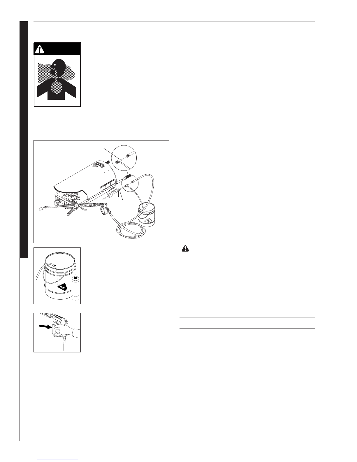
TRIGGER GUN KICKS
BACK - HOLD WITH
BOTH HANDS
WARNING: Spray gun kicks
back — hold with both hands.
9. Grip cleaning wand securely
with both hands before starting.
Failure to do this could result in
injury from a whipping wand.
Thank you for purchasing a Landa Pressure Washer.
This manual covers the operation and maintenance
of the HS-3000 heater module. All information in this
manual is based on the latest product information
available at the time of printing.
Landa, Inc. reserves the right to make changes at any
time without incurring any obligation.
Owner/User Responsibility:
The owner and/or user must have an understanding
of the manufacturer’s operating instructions and
warnings before using this Landa pressure washer.
Warning information should be emphasized and un-
derstood. If the operator is not fluent in English, the
manufacturer’s instructions and warnings shall be read
to and discussed with the operator in the operator’s
native language by the purchaser/owner, making sure
that the operator comprehends its contents.
Owner and/or user must study and maintain for future
reference the manufacturers’ instructions.
SAVE THESE INSTRUCTIONS
This manual should be considered a permanent
part of the machine and should remain with it if
machine is resold.
When ordering parts, please specify model and
serial number. Use only identical replacement
parts.
This machine is to be used only by trained opera-
tors.
CAUTION:To reduce the risk of
injury, read operating instruc-
tions carefully before using.
1. Read the owner's manual
thoroughly. Failure to follow
instructions could cause
malfunction of the machine
and result in death, serious
bodily injury and/or property
damage.
2. Know how to stop this product and bleed pressures
quickly. Be thoroughly familiar with the controls.
3. Stay alert - watch what you are doing.
4. All installations must comply with local codes.
Contact your electrician, plumber, utility company
or the selling distributor for specific details.
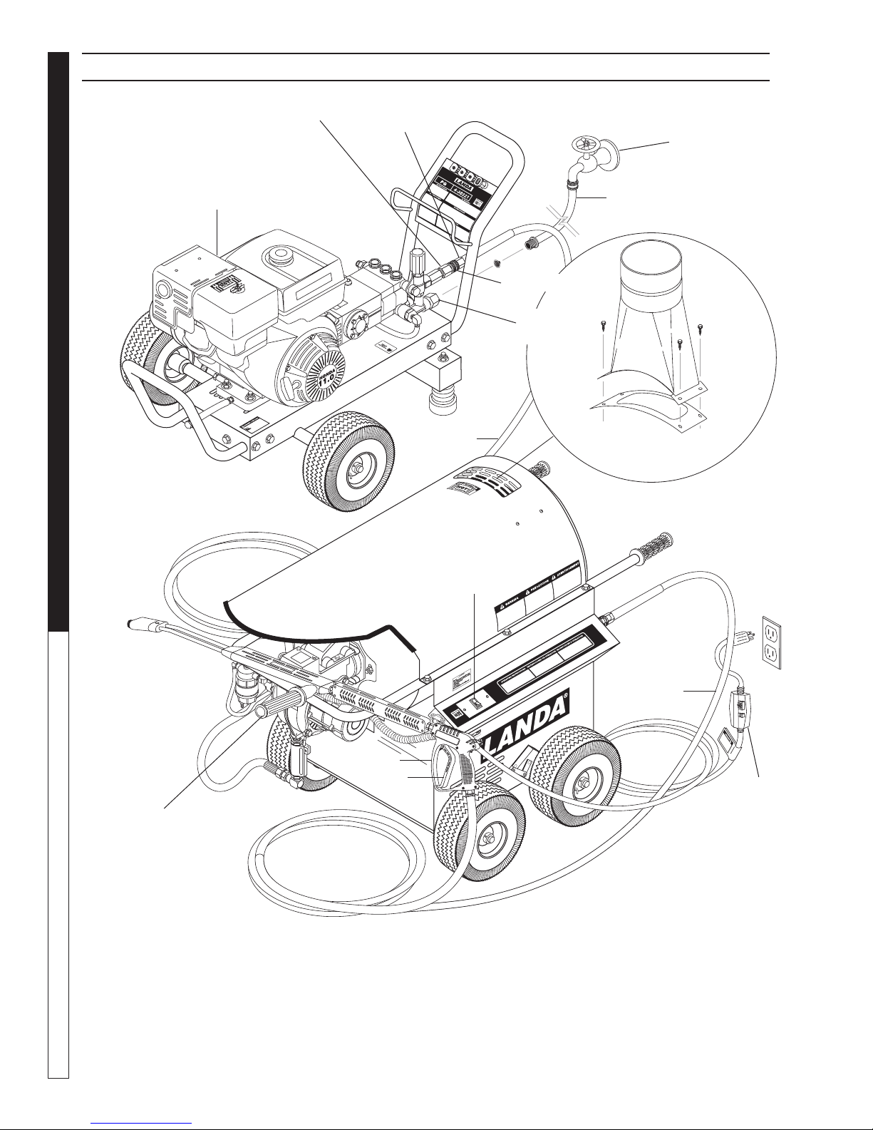
To comply with the National Electric Code (NFPA
70) and provide additional protection from risk of
shock, this product is provided with a ground fault
circuit interrupter (GFCI) built into the power cord
plug (250V 30 amp or less, 1 PH). If replacement
of the plug or cord is needed, use only identical
replacement parts.
DANGER: Improper connection of the equipment-
grounding conductor can result in a risk of elec-
trocution. Check with a qualified electrician or
service personnel if you are in doubt as to whether
the outlet is properly grounded. Do not modify the
plug provided with the product - if it will not fit the
outlet, have a proper outlet installed by a qualified
electrician.
WARNING: Do not operate near
flammable liquids which can
create fumes and can ignite
causing property damage or
severe injury.
WARNING: Do not use gaso-
line, crankcase drainings or oil
containing gasoline, solvents
or alcohol. Doing so will result
in fire and/or explosion.
WARNING: Do not spray flammable liquids.
Operate only where an open torch is permitted.
5. This oil burning machine shall be installed only in
locations where combustible dusts and flammable
gases or vapors are not present.
6. In these oil burning models, use only kerosene,
No. 1 home heating fuel, or diesel.
7. Risk of explosion - do not spray flammable
liquids. Operate only where open flame or torch is
permitted.
WARNING: Keep water spray,
wand and high pressure hose
away from electric wiring or
fatal electric shock may result.
Read warning tag on electrical
cord.
8. To protect the operator from
electrical shock, the machine
must be electrically ground-
ed. It is the responsibility of the owner to connect
this machine to a UL grounded receptacle of proper
voltage and amperage ratings. Do not spray water
on or near electrical components. Do not touch
machine with wet hands or while standing in water.
Always disconnect power before servicing.
KEEP WATER SPRAY
AWAY FROM ELEC-
TRICAL WIRING.
READ OPERATOR’S
MANUAL THOROUGHLY
PRIOR TO USE.
RISK OF FIRE.
DO NOT USE WITH
FLAMMABLE LIQUIDS.
INTRODUCTION & IMPORTANT SAFETY INSTRUCTIONS