Mounting Location
Placement
Choose a location:
•Away from interference caused by power and radiation sources
such as: the propeller(s) and shaft(s), other machinery, other
echosounders, and other cables. The lower the noise level, the
higher the echosounder gain setting that can be used.
• Where the transducer will be continuously immersed in water.
•Where the transducer beam will be unobstructed by the keel or
propeller shaft(s).
•Where there is a minimum deadrise angle, not exceeding the tilt
angle of your transducer.
Caution
: Do not mount in an area of turbulence or bubbles:
Near water intake or discharge openings,
Behind strakes, fittings, or hull irregularities.
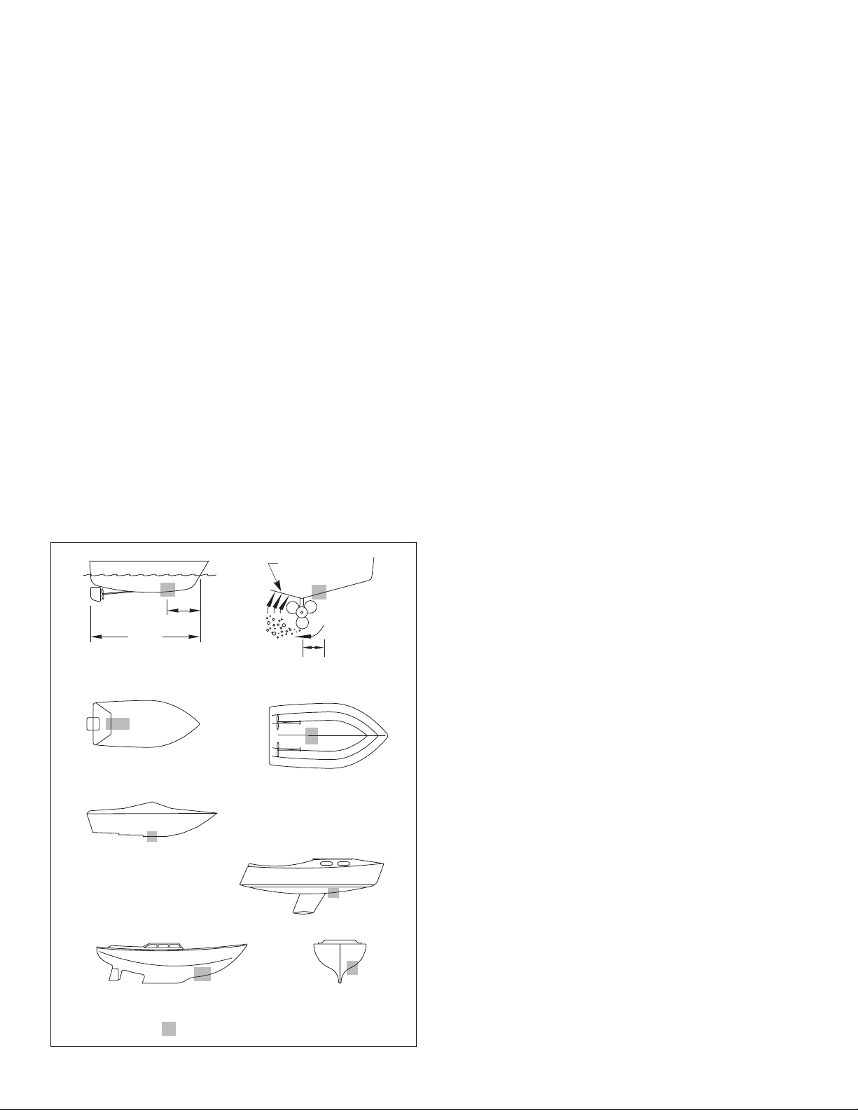
Boat Types
(see Figure 3)
•
Displacement hull powerboat
—Locate 1/3 aft LWL and
150–300mm (6–12") off the centerline on the side of the hull
where the propeller blades are moving downward.
•
Planing hull powerboat
—Mount well aft, on or near the
centerline, and
well inboard of the first set of lifting strakes
to
insure that the transducer is in contact with the water at high
speeds. Mount on the side of the hull where the propeller
blades are moving downward.
Outboard and I/O
—Mount just forward of the engine(s).
Inboard
—Mount well ahead of the propeller(s) and shaft(s).
Stepped hull
—Mount just ahead of the first step.
Boat capable of speeds above 25kn
(29MPH)—Review the
installation location and operating results of similar boats before
proceeding.
•
Fin keel sailboat
—Mount to the side of the centerline and
forward of the fin keel 300–600mm (1–2').
•
Full keel sailboat
—Locate amidships and away from the keel
at the point of minimum deadrise angle.
Installation
Cored fiberglass hull
—Follow separate instructions on page 3.
Hole Drilling
Warning
: Always wear safety goggles and a dust mask.
1. Drill a 3 mm or 1/8" pilot hole from inside the hull. If there is a rib,
strut, or other hull irregularity near the selected mounting
location, drill from the outside.
2. Using the appropriate size hole saw, cut a hole from outside of
the hull perpendicular to the hull surface (see “Tools &
Materials” on page 1).
Stainless steel housing
—These models require
countersinking the housing to create a “seat” in the hull.
3. Sand and clean the area around the hole, inside and outside, to
ensure that the sealant will adhere properly to the hull. If there is
any petroleum residue inside the hull, remove it with either mild
household detergent or a weak solvent (alcohol) before sanding.
Metal hull
—Remove all burrs with a file and sandpaper.
Bedding
Caution
: Never pull, carry, or hold the transducer by its cable; this
may sever internal connections.
Apply a 2mm (1/16") thick layer of sealant around the lip of the
housing that contacts the hull and up the sidewall of the housing
(see Figure 4). The sealant
must
extend 6mm (1/4") higher than
the combined thickness of the hull, washer(s), and the hull nut.
This will ensure there is sealant in the threads to seal the hull and
to hold the hull nut securely in place.
Stainless steel housing in a metal hull
—To prevent electrolytic
corrosion, the stainless steel housing
must
be isolated from the
metal hull. Slide the isolation bushing onto the housing, then apply
additional
sealant to the surfaces of the bushing that will contact
the hull.
Installing
1. From outside the hull, push the housing into the mounting hole using
a twisting motion to squeeze out excess sealant (see Figure 4).
Caution: The arrow on the top of the transducer must point
toward the keel.
2.
From inside the hull,
point the arrow on the top of the transducer
toward the keel
(see Figure 1). This will align the angle of the
element inside the transducer with the deadrise angle of your hull.
3. Slide the washer onto the housing (see Figure 4).
4. Screw the hull nut in place.
Plastic housing
—
Do not
clamp the wrench flats tightly, to
avoid possibly fracturing the housing.
Plastic hull nut
—
Hand-tighten
only.
Do not
over-tighten.
Bronze hull nut
—Tighten with slip-joint pliers.
Wood hull
—Allow the wood to swell before tightening the hull nut.
5. Remove any excess sealant on the outside of the hull to ensure
smooth water flow over the transducer.
2
inboard
Figure 3.
pressure waves
1/3 aft
full keel sailboat
displacement hull
(6-12")
fin keel sailboat
150-300mm
LWL
Best location for the transducer
(Load Waterline Length)
stepped hull
outboard and I/O
planing hulls
Copyright © 2005 Airmar Technology Corp.


