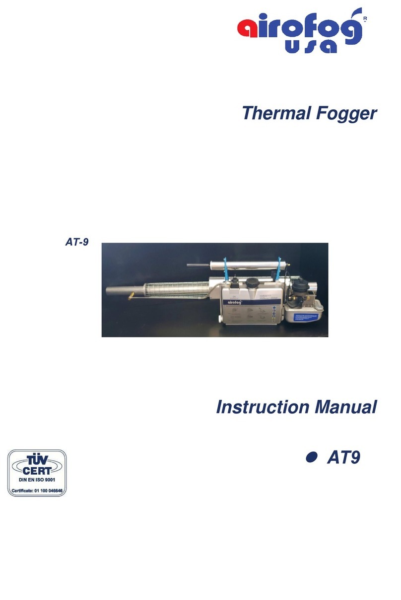
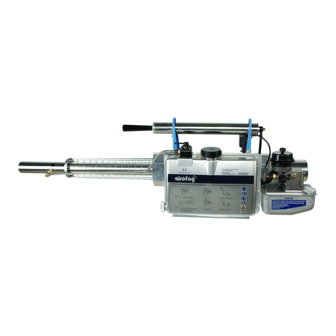
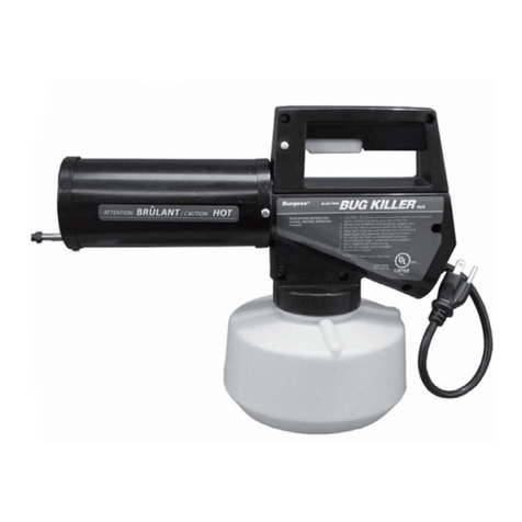
Airofog AR-9 User manual

~1~
Table of Content
(1). GENERAL INFORMATION 1
(2). CERTIFICATE OF GUARANTEE 2
(3). 1. Mode of Operation 3
(4). 2. Technical Specifications 4
(5). 3. Standard Accessories 5
(6). 4. Optional Accessories 5
(7). 5. Safety Instructions 6 - 7
(8). 6. To Prepare the Appliance Ready for Use 8 - 10
(9). 7. Select Fog Solution Output and Fog Tube 11
(10). 8. Fogging Mixture 12
(11). 9. Starting the Appliance 13
(12). 10. Appliance Stops Unexpectedly 14
(13). 11. Stopping the Appliance 15
(14). 12. Correct Adjustment of the Appliance 16
(15). 13. Maintenance & Store the Appliance 17 - 18
(16). 14. Touble Shooting 19 - 21
(17). 15. Emergency Cut-off Device 22 - 23
(18). 16. Fogging with “EC” 24
(19). 17. Stopping the Appliance with “EC” 24
(20). 18. If “EC” Does Not Function or Not Function Correctly 25
(21). Thermal Fogger AR9/AR35 Spare Part List 26 - 30
(22). Thermal Fogger AR9/AR35 Explosion Drawing 31
(23). “EC” Explosion Drawing 32
(24). “EC” Spare Part List 33
THERMAL FOGGER GENERAL INFORMATION
Thank you for purchasing AIROFOG quality product. We wish you all the
success on the application and believe you will be fully satisfied with its
performance.
These instructions expatiate all the information necessary for the use of the
application by means of explosion drawings, receipt, start-up, operation,
maintenance, cleaning, trouble-shooting and etc. as well as all the safety
precautions to be taken throughout the lifetime of the appliance.
All Airofog pulse-jet thermal foggers are in conformity with the EC Council
Directive 2004/108/EC Electromagnetic Compatibility, the model AR9E &
AR35E are manufactured in accordance with the World Health Organization
“EQUIPMENT FOR VECTOR CONTROL SPECIFICTION GUIDELINES”
WHO/CDS/NTD/WHOPES/GCDPP/2006.5.
All data and information concerning in this instruction manual are based on
and given to the best of our experience and knowledge sofar. This manual
might change to meet our technical improvement without notice along with
the continuous technological development.
Please feel free to contact us for technical update.
Definition of the symbols used:
The CE mark indicates that the appliance conforms to the EC directive.
General warning, risk of danger or possibility of damaging the appliance,
pay particular attention to the words that follow this symbol.
All other relevant advice.
!
☞
V. 232126

1. Mode of Operation
The Airofog pulse-jet thermal foggers operate on the principle of the one-sided
open jet-tube (resonator) with a valve at the inlet side (carburetor) and an open
outlet (fog outlet). This pulse-jet system (operating without any moving parts) that
consists of a carburetor, mixer tube, combustion chamber and resonator, consti-
tutes an acoustical oscillation system at an optimum frequency.
At the end of the resonator, fogging solution is injected in the air stream emerging
at high velocity, and is dispersed into the finest aerosol droplets and distributed into
a lightly suspended fog.
The temperature at the point where the fogging solution is fed in is in the range of
400-600C with the solution being exposed to the heat for not more than 4 to 5
milliseconds. Therefore heat sensitive substances can also be used.
~3~
Oil
1
23
5
6
7
8
9
10
11
12
15
14
13
4
Fig.1
16
18
17
1.
fog tube (108) 10. gasoline stop button (52)
2. solution socket (114) 11. carburetor (23)
3. dosage nozzle (117) 12. air intake valve (30)
4. solution line (116) 13. starter button (78)
5. solution tap (120) 14. air pump (89)
6. battery cover (71) 15. cooling jacket (100)
7. solution tank (1) 16. resonator (97)
8. swirl vane (26) 17. emergency cut-off device
9. gasoline tank (10) 18. connecting piece Bowden cable
CERTIFICATE OF GUARANTEE
AIROFOG MACHINERY CO., LTD. (called AIROFOG) guarantees all
“Airofog” thermal fogger to be free of defects in materials or workmanship
to the original purchaser for a period of one (1) year, on labor and parts
which are not subject to usual wear.
During this period, AIROFOG will replace and/or repair the parts with mate-
rial and/or manufacturing faults (on the exclusive judgement of our technical
department) free of charge.
The despatch and return expenses will be paid by the customer.
The guarantee does not cover any damage occurred during transport or by
incorrect handling, tempering, improper use, the use of non-recommended
products and so on.
Under no circumstances will AIROFOG be liable for damages due to
improper use or application. Under no circumstances will AIROFOG be
responsible for damages done to any property or persons.
~2~

~5~
~4~
2. Technical Specifications:
Technical specifications are also applicable for AR9E & AR35E.
AR9 AR35
Combustion chamber output, approx. 11 KW / 15 PS 18.7 KW / 25.4 PS
Fuel tank
capacity 1.2 L 1.2 L
pressure in the fuel tank, approx. 0.08 bar 0.08 bar
fuel consumption, approx. 1.2 L/H 2 L/H
fuel standard grade gasoline,
without any additives
Solution tank
total capacity 6 L 6 L
liquid capacity, approx. 5.7 L 5.7 L
pressure in the solution tank, approx. 0.3 bar 0.3 bar
Ignition
electronic ignition coil, 4 x 1.5 V 4 x 1.5 V
supplied from dry batteries size “AA” or “D
spark plug not request not request
Weight (empty), approx. 7.0 kg 7.6 kg
with emergency cut-off device 7.4 kg 8.0 kg
Dimensions
wide x height 27 x 34 cm 27 x 34 cm
length, with oil-base fog tube 113.5 cm 137.5 cm
length, with water-base fog tube 109 cm 133 cm
3. Standard Accessories:
AR9 AR35
- Set of solution dosage nozzle 0.8 0.8
1.0 1.0
X 1.2
- Solution suction tube √ √
- Fuel funnel with strainer √ √
- Solution funnel with strainer √ √
- Set of repair tools √ √
- Set of cleaning tools √ √
- Tool bag √ √
- Carrying strap √ √
- Ear protector √ √
- Maintenance kit √ √
- Instruction Manuel √ √
4. Optional Accessories:
- Batteries, 1.5 V, Alkaline, LR20 / size “D”
- Batteries, 1.5 V, Alkaline, LR6 / size “AA”
- Solution dosage nozzle 0.6
0.7
1.4
1.6
- Special fog tube for water base solution (109)
- Fog solution socket (114/1) for water base fog solution
- Emergency cut-off device (called “EC”)
- Silencer
All rights to technical alteration reserved.

~7~
5. Safety Instructions:
● Please read carefully and understand this instruction manual before working
on or operating the appliance to avoid potential problems.
● Keep this manual. If the appliance is transferred, give the manual to the
new owner.
● Use the appliance only for the purpose it was designed for.
● ONLY educated and authorized persons are allowed to work with appliance.
● Before use, operators must be aware of all protection and safety measures.
● Persons with pace-makers should consult their doctors before operating
or servicing the appliance due to an electronic ignition coil in the start system.
● Before operation, make sure the appliance is fully and correctly assembled,
no damage and leaks, the sealing is in order. Do not fog if the appliance
is not running perfectly.
● When fogging, use protective equipment, proper respiratory protection,
protective gloves and ear protectors as applicable.
● During operation, never leave the appliance unattended.
● When carry the appliance with the carrying strap, the belt should be carried
on the same shoulder which carries the appliance. Not to cross the belt
over the neck.
● During operation, persons, animals or combustible materials must not be
in front of the fog tube.
● For portable use, carry the appliance with the fog tube pointing rearwards.
Hold the appliance horizontally or incline it slightly downwards. Walk
only forward.
● Outdoors you should fog in the wind direction, indoors fog in such a way
that you leave the treated areas through untreated areas in the exit direction.
Avoid such excessive spraying that could adversely affect your visibility
for quick exit.
~6~
● Follow the chemical supplier’s instructions for the safety and mixing of
chemical.
● Never apply a pesticides, desinfectant or odor counteractant at application
rates higher than what is the manufacturer’s specified.
● Never exceed quantity specified or formulation label instruction when
fogging within an enclosed space.
● When filling with gasoline, make sure the appliance is cool and there
is no spill.
● Avoid touching hot parts to prevent burns. After operations, allow
reasonable time for the appliance to cool down before further handling.
● Do not transport the appliance in closed vehicles while still warm.
● Do not fog combustible liquids into pipes or tunnels without ventilation
because of fire and explosion hazard.
● Always keep ABC fire extinguisher ready when fogging combustible
formulation.
● Smoking is forbidden when using fuel. Avoid exposure to open flame.
● Do not fog where there is a danger of dust explosion (e.g. grain mills).
● Never invert or upset appliance which contains formulation or fuel.
● Never ship the appliance with fuel or agent in the tank.
● Do not fog directly against walls or other fixed objects. Keep a distance
of minimum 3m.
● For stationary operation, ensure appliance is properly supported on a
horizontal surface.
● Always reattach safety devices when repair work is completed.
● Never modify the appliance.

~9~
~8~
6. To Prepare the Appliance Ready for Use:
The appliance comes packed in a cardboard box. Check that it is in undamaged condition
after removing it from the box.
It is only for packing purposes that the fog tube is not fitted.
To avoid overheating the appliance, start the appliance ONLY after the fog tube
(108 / 109) is fitted (Fig. 2 & 3) with the resonator.
Pull out the fog tube (108) from the
cooling jacket (100), select appropriate
connection (oil-base or water base)
and push back the fog tube into the
cooling jacket, allowing the tube hole
to line up with the resonator (101)
thread.
(Fig. 2)
After screwing in the fog solution
socket
(114) by hand, join the solution
dosage
nozzle (117) to solution tube
(116) together
with copper gaskets (118)
to the solution
socket (114).
It is necessary to counter
hold with the
second spanner at the hexagon
of the
solutions socket.
(Fig. 3)
Insert batteries as per diagram. The
positive
pole is situated in front of the
gasoline tank
(10) and the negative
pole on the battery
cover (71).
(Fig. 4)
For better performance, use
Alkaline batteries.
71 Fig.4
10
Oil
101
108
100
Fig.2
Water
108
Oil
116
114
118
117
Fig.3
118
To install it in operating
position:
!
☞
144
Fig.6
Check ignition coil by pressing
starter button (78). A buzzing
sound is easily
audible.
(Fig. 5)
Fill fuel tank with normal grade
gasoline,
without any additives.
There is no advantage to use
premium gasoline with a higher
octane rating.
Always use gasoline
funnel(144)
with filter.
(Fig. 6)
Never fill the fuel tank
when the appliance is hot.
After filling, tighten gasoline cap
(7) firmly
by hand.
Push stop
button (52) of gasoline control
fully in to stop position.
(Fig. 7)
78
Fig.5
Fig.7
52
7
!
1)
2)
3)
4)
5)
6)

~11~
~10~
Fill solution tank (1). Always use
solution funnel (143) with filter.
(Fig. 8)
Only fill the required solution amount
for application.
NEVER fill the fuel into the
solution tank (1).
Place tank cap (2) in proper position
then close it tightly.
Make sure that solution tap
(120) is
closed. Lever points upwards.
(Fig. 9)
Tighten the air intake valve (30) and
swirl vane (26).
(Fig. 10)
143
Fig.8
120
2
Fig.9
7)
8)
30
26 Fig.10
9)
!
1
7. Select Fog Solution Output and Fog Tube:
Solution throughput of the available dosage nozzle (measured with water).
Solution nozzle size Ø throughput L/H, approx.
0.6 5
0.7 8
0.8 12
1.0 18
1.2 23
1.4 36
1.6 42
The outputs vary according to different chemicals and physical propertises
of the formulations. We advice that you do your own metering of the output
under prevailing conditions.
For water based solutions choose nozzles up to Ø1.0 mm.
For better performance, we recommend special fog tube (109) and fog solution
socket (114/1) for water based product.
For oil based solutions we recommend nozzle sizes Ø 0.8 and above.
Then use the standard oil based fog tube (108) ONLY.
Smaller nozzles reduce the droplet spectrum. Larger nozzles may cause
an unsatisfactory droplet spectrum.
Never operate the appliance with the water based fog tube when oil
based fogging mixtures with carriers of inflammable substances are
applied.
!

~13~
~12~
8. Fogging Mixture:
Principally preparations of the chemical industry and biological products, which
can be mixed either with water or with oily carrying mediums, can be fogged.
Carrying mediums for fogging are:
• for preparations miscible with water:
1. pure water
2. special fog carriers, e.g. glycerin, glycols
3. white oils with suitable emulgators
4. a mixture of 1. and 2. or 1. and 3.
• for preparations miscible with oil:
5. diesel oil, heating oil or kerosene
6. white oils and vegetable oils in a viscosity similar to diesel oil
7. special fog carriers
When fogging indoor, it is essential that fire precaution is taken.
All naked lights must be extinguished and electricity turned off.
It is recommended that with oil-based pesticide formulations not
more than 1 liter per 400m3be released in order to avoid any
fire risk. A single spark can set off an explosion when more than
1 liter of a formulation containing kerosene is fogged per 300m3.
Observe applicable laws when selecting active solution and/or
carriers.
We cannot be held responsible for damages to person or to property,
directly or indirectly, due to unsuitable fogging
solutions or incorrect
dosage.
!
☞
52
Fig.11
Fig.12
78
91
9. Starting the Appliance:
OPEN
CLOSE
Fig.13
120
1) Pull stop button (52) outwards.
(Fig. 11)
2) Press starter button (78) and keep
press actuate air pump (91). Pump
regularly and evenly. When the first
explosion is audible, pump another
1~2 strokes.
(Fig. 12)
3) After starting, let the appliance warm up
for about 1 minute.
- open the solution tap (120), the appliance
will fog
- in order to stop fogging, close solution
tap (120).
(Fig. 13)
The lower the gasoline in the tank, the more pumping strokes are
necessary.
Therefore, when possible, always start with a full tank.
Make sure that the gasoline volume is sufficient for the intented
period of fogging.
If your appliance is equipped with an emergency cut-off device
(AR9E / AR35E), always check the function of the device in
accordance with para. 15 “Check of function”.
!
☞
!
☞

~15~
~14~
10. The Appliance Stops Unexpectedly
Take the following urgent measures when the appliance stops unexpectedly
due to a lack of fuel or mechanical failure:
- Close the solution tap (120) immediately.
Close the solution tap to avoid the fogging
mixture being conveyed by the over -
pressure in the solution tank and reaching
into the hot resonator without being
fogged.
There combustible fogging mixtures can
ignite, thereby creating the risk of fire at
the carburetor and / or fogging outlet.
(Fig. 14)
- Hold the appliance with the fog mixing
tube pointing downwards.
The appliance has to be held with the
fog mixing tube pointing downwards
to allow the chemical solution residue
to run out. Small quantities of
combustible solution can ignite and
have to be extinguished immediately.
(Fig. 15)
It is not allowed to leave the appliance unattended while operating in any case.
Fig.14
120
Fig.15
Oil
!
11. Stopping the Appliance:
1) Close solution tap (120) by 1/4 turn to clear
or ventilate the solution pipe (116).
(Fig. 16)
2) Wait until fog is no longer visible. Now close
solution tap (120) completely(lever upwards).
(Fig. 17)
3) Press stop button (52) until no explosions are
audible.
(Fig. 18)
4) Release pressure from solution tank by
unscrewing the solution tank cap (2) by 1 to 2
turns then retighten the cap.
(Fig. 19)
After stop the appliance always release
pressure from solution tank because the
solution tank is still under pressure and
solution can get out when the solution tap
open by mistake.
Fig.16
120
116
120
Fig.17
52
Fig.18
Fig.19
2
!

~17~
~16~
12. Correct Adjustment of the Appliance:
• Turn regulating needle (17) approx. 1/2
counter clockwise then start the appliance.
(Fig. 20)
• Let the appliance warm up for at least 1
minute.
• Check the flame at the resonator (101)
end by obliquely looking into the resonator
at a safe distance (approx. 2m).
Wear safety glasses for protection.
• For fine adjustment, cautiously screw the
regulating needle (17) clockwise or counter
clockwise until the flame is no longer
visible.
(Fig. 21)
When the adjustment is correct the
running is steadily strong and no flame
appears from the resonator end.
NEVER run the appliance over -
adjustment (high frequency sound,
flame appears from the fog tube)
because this causes power loss and
overheating, and may lead to fire hazard.
Due to big differences in outside conditions such as climate and sea-level, the
appliance must be re-adjusted although every appliance is checked before delivery.
Please fill the fuel tank at least 2/3 full then correct adjustmen in the following steps:
“OVERFLOW”:
It is possible that by too vigorous pumping the carburetor overflows and
gasoline fumes emerge out at the end of the fog tube (108/109). In this
case, close fuel stop button (52), press the starter button (78) and actuate
air pump (91) until no more explosions are audible. Then restart as normal
but do not pump too vigorously.
17
Fig.20
17
Fig.21
☞
!
13. Maintenance & Store the Appliance:
To ensure the appliance is ready for use at all times, we recommend before storage:
a) Rinse the empty solution tank and
clean.
Pour approx. 1/4L of water into the
solution tank, shake well and fog to
clear pipe system.
b) Clean appliance of any outside dirt.
c) Remove diaphragm (33) in air intake
valve (30). Check for any damage
and clean. Clean also the valve body
(34), the spacer plate (32) and the
silencer (60) with a soft cloth and
with gasoline.
(Fig. 22)
d) Remove residue in resonator (101)
end, solution socket (114), dosage
nozzle (117) and possibly fog tube
(108/109) with the scraper and the
wire brush.
(Fig. 23)
Oil
114 117
Fig.23
101
108
60
63/1
34
33
32
63
30
Fig.22
34/1
It is important that any soot or carbon deposits at the end of the resonator
tube should not be allowed to remain.
!
!
☞

~19~
~18~
e) Clean mixing pipe of resonator (101)
of combustion residues with scraper
(141).
(Fig. 24)
f) Clean mixing chamber of the
carburettor (24) with brush (142).
Take care not to damage the fuel
atomizer nozzle.
(Fig. 25)
g) Clean swirl vane with wire brush.
(Fig. 26)
h) Empty fuel tank (10) when the appliance
is cold.
Do not close the tank cap (7) tight.
(Fig. 27)
101
141
Fig.24
Remove the batteries from the appliance when it is stored for a longer period.
Store the appliance at places where they are not accessible to children and
other persons who may not be aware of dangers involved.
Fig.27
7
10
- Only qualified person is authorized to carry out repairs.
- Use only original spare parts.
- Before repair, stop the appliance and allow a cooling time. Remove the spark
plug socket from the swirl vane.
-
During repair and tests, at all times avoid touching electrically live components
.
- After repair, reassemble the safety devices (e.g. protection guards) and check
for correct assembly of all parts.
- After each repair, do a functional fogging test with the neat water.
-
It is recommended that you have your appliance checked regularly
by a suitably
qualified technician (e.g. by the approved manufacturer’s representative).
14. Trouble Shooting:
PLEASE FEEL FREE TO CONTACT US OR YOUR LOCAL DISTRIBUTOR
FOR TECHNICAL ASSISTANCE.
☞
!
Fig.26
Fig.25
24
142

~21~
~20~
If the appliance does not start and / or runs unevenly
Check first:
- Are all three caps of gasoline and solution tank closed and sealed well?
Check also the gaskets of the caps.
- Is there gasoline in the fuel tank?
- Check the batteries.
- Do you hear the ignition coil buzzing while pressing the start button?
- Decrease of pressure in the emergency cut-off device (AR9E / AR35E)
Possible causes: Check:
- no ignition - batteries weak or lose contact, starter button or
ignition coil faulty, swirl vane dirt or wet, mixing
tube of resonator dirty
- no gasoline supply - gasoline supply is sufficient
- clogged at gasoline supply
● unscrew regulating needle (17), actuate air
pump (91), gasoline should appear
● if fuel tank cap seals well
- water in the gasoline - empty and clean fuel tank, refill new gasoline
- atomizer dirty or clogged - clean only with gasoline and compressed air
- diaphragm in the air intake - clean or replace if necessary
valve damaged or dirty
- carburetor dirty - clean the mixing chamber only with brass
brush and gasoline, blow with compressed air
- resonator dirty - remove combustion residues from the resonator
(101) end and the mixing pipe with scraper and
brass brush
- wrong adjustment of the - see para. (12)
appliance “Correct Adjustment of the Appliance”
Check first:
- Is there sufficient solution in the tank?
- If the pressure hose is correctly installed?
- If the solution conveying parts are blocked or leaked?
Possible causes: Check:
- no or insufficient pressure - solution tank leaks
in solution tank (1) - check valve is clean or defective
● when replacing diaphragm (40), always
replace it together with o-ring (41) and
gasket (42)
- connecting links (43) loose or damage
● when necessary, always replace it
together with gasket (44)
- pressure hose (133, 134/1, 134/2) leaks
or damages
- residue in double hollow screw (132) ,
clean with fine wire if necessary
- tank cap (2) leaks
● check gasket (4) and replace if
necessary
- solution tap (120) defective - the gaskets (125, 126) damage, replace
or clogged it if necessary
● clean all parts of solution tap before
re-assembly and check for leakage
- dosage nozzle (117) clogged - clean with fine wire for free passage
- fog solution socket (114) clogged - clean with fine wire for free passage
If the appliance runs but does not fog or fogs irregularly

~23~
~22~
1) Prepare the appliance in the normal way
and start, then let it warm up for at least
1 minute. Engage the operating lever
(EC13) for appr. 10 sec. and stop the
appliance. The operating lever must be
released automatically.
(Fig. 29)
AR9E / AR35E is equipped with an emgency cut-off device (called “EC”). Every
appliance was given the final inspection at the factory of manufacturer, so adjustment
is not needed when starting the appliance. However, it is necessary after a repair or
blocking.
Check of function. Please proceed as follows:
15. Emergency Cut-off Device
EC 13
Fig. 29
Engage
Release
2) Start the appliance and engage the
operating lever.
Open solution tap (120), now fogging
thrust should be seen.
(Fig. 30)
3) Stop the appliance, operating lever will be
released automatically, the fogging should
stop now.
(Fig. 31)
4) Check no solution leak from screw
housing (EC27), valve housing (EC33)
and solution nozzle (114).
(Fig. 32)
EC13
OPEN
Fig.31
Release
Oil
Fig.32
EC27
EC33
114
!
After every check of function, immediately close solution tap and release
pressure from solution tank by loosen the tank cap.
Always check the function of the “EC” when starting. The appliance may only be
operated when the “EC” function correctly.
EC 25 EC 24
Fig.28 EC 23
The fine adjustment of the Bowden Cable (EC23)
can only be effective when the appliance is warm
up:
- ajust the tension of the Bowden Cable (EC23)
by tuning the screw-type nipple (EC25)
inwards / outwards.
- after correct adjustment, tighten the nut (EC24).
(Fig. 28)
EC 13
Engage
120
Fig.30

~25~
~24~
EC 13
Fig.33
Engage
120
OPEN
CLOSE
16. Fogging with “EC”:
- Engage the operating lever (EC13) and lock its
position by piston.
- For fogging, open the solution tap (120), lever
downwards.
- In order to stop fogging with the “EC” engaged,
close the solution tap, lever upwards.
(Fig. 33)
17. Stopping the appliance with “EC”:
1. To stop the appliance normally, refer to para. 11 (Stopping the Appliance).
2. Appliance stops unexpectedly due to a lack
of fuel or mechanical failure.
- When the appliance stops unexpectedly, the
“EC” is released automatically and stops
conveying of solution.
- Close the solution tap (120) completely (lever
upwards) and release pressure from solution
tank by loosen tank cap (2) immediately,
because the solution tank is still under
pressure and solution can get out when the
operating lever is activated by mistake.
(Fig. 34)
Fig.34
EC 13
2
Loosen
120
Close
18. If “EC” does not function or not function correctly:
Check first:
- Appliance runs too weakly.
- Decrease of pressure in the “EC” device
Possible causes:
- appliance stops, operating lever
does not release automatically
- appliance in operation, operating
lever can not engage
- appliance in operation and
operating lever releases,
fog does not stop
- appliance in operation and
operating lever engage, no fog
- solution leaks out of screw housing
(EC27) or valve housing (EC33)
or solution socket (114) when
appliance stops, operating lever
releases and solution tap opens.
Check:
- incorrect setting of screw-type nipple
(EC25) at the Bowden cable (EC23)
- piston (EC8) is not pushed back into
initial position.
- spring (EC9) too weak or broken
- the diaphragm (EC6) of the pressure
cell is damaged or dirty
- incorrect setting of screw-type nipple
(EC25) at the Bowden cable (EC23)
- piston (EC8) is not pushed forward
- spring (EC9) too strong
- the diaphragm (EC6) of the pressure
cell is damaged or dirty
- leak of pressure in the “EC” system
- clog of air pressure tube (EC20)
- incorrect setting of screw-type nipple
(EC25) at the Bowden cable (EC23)
- spring (EC28) too weak or broken
- damage of o-ring (EC32)
- valve housing (EC33) dirty
- incorrect setting of screw-type nipple
(EC25) at the Bowden cable (EC23)
- damage of Bowden cable (EC23)
- clog of valve housing (EC33) or solution
nozzle (117) or solution socket (114)
- solution tap (120) does not open
- damage of o-ring (EC31)
- damage of o-ring (EC32)
- spring (EC28) too weak or broken

~27~
~26~
Thermal Fogger AR9 / AR35 Spare Part List
When ordering spare parts, please always mention the pos., part number,
descriptions, number of parts needed.
note: the part without “ # ” is commonly suitable for all appliance types.
the part with “ # ” can only be used on particular mentioned appliance type.
Pos. Part no. Descriptions
1 935-001-000 Solution tank
2 935-002-000 Tank cap, cpl., consisting of part 3-4
3 935-003-000 Cover
3/1 935-003-010 Lever indicator
4 935-004-000 O-Ring
5 935-005-000 Edge protection
7 935-007-000 Cap, cpl., consisting of part 8-9
8 935-008-000 Cap
9 935-009-000 Gasket
10 935-010-000 Fuel tank
12 935-012-000 Carburetor cover
13 935-013-000 Gasket
15 935-015-000 O-Ring
16 935-016-000 Regulating needle,cpl., consisting of part 17-18
17 935-017-000 Regulating needle
18 935-018-000 O-Ring
19 # 935-019-000 Atomizer nozzle cpl. AR35, consisting of part 20-22
19 # 909-019-000 Atomizer nozzle cpl. AR9, consisting of part 20-22
20 # 935-020-000 Atomizer nozzle AR35
20 # 909-020-000 Atomizer nozzle AR9
21 935-021-000 O-Ring
22 935-022-000 O-Ring
23 # 935-023-000 Carburetor (consisting of part no. 24, 25x2) AR35
23 # 909-023-000 Carburetor (consisting of part no. 24, 25x2) AR9
23/1 # 935-023-010 Carburetor cpl. AR35 (consisting of part
12,13,15,16,19,23,26, 27/1,30,35,36x4,40,41,42,43,44,49)
23/1 # 909-023-010 Carburetor cpl. AR9 (consisting of part
12,13,15,16,19,23,26, 27/1,30,35,36x4,40,41,42,43,44,49)
24 # 935-024-000 Carburetor housing AR35
24 # 909-024-000 Carburetor housing AR9
25 935-025-000 Set screw, M6x20
26 # 935-026-000 Swirl vane AR35
26 # 909-026-000 Swirl vane AR9
27 # 935-027-000 O-Ring AR35
27 # 909-027-000 O-Ring AR9
27/1 935-027-010 O-Ring
29 935-029-000 O-Ring
Pos. Part no. Descriptions
30 # 935-030-000 Air intake valve cpl. AR35, consisting of part 32-34, 34/1,
60, 63, 63/1
30 # 909-030-000 Air intake valve cpl. AR9, consisting of part 32-34, 34/1,
60, 63, 63/1
32 # 935-032-000 Spacer plate AR35
32 # 909-032-000 Spacer plate AR9
33 935-033-000 Diaphragm
34 # 935-034-000 Valve body AR35
34 # 909-034-000 Valve body AR9
34/1 935-034-010 O-ring
35 935-035-000 Cap nut, M5
36 935-036-000 Fill.head screw, M4 x 12
37 935-037-000 Gasket
38 935-038-000 Valve, consisting of part 39,40,41
38/1 935-038-010 Valve cpl., consisting of part 35,38,42,43,44
39 935-039-000 Valve
40 935-040-000 Diaphragm
41 935-041-000 O-Ring
42 935-042-000 Gasket
43 935-043-000 Connecting link
44 935-044-000 Gasket
46 935-046-000 Tube
47 935-047-000 Screwed socket
49 935-049-000 Gasoline stop button,cpl., consisting of part 18, 29, 50-52
50 935-050-000 Plunger, H59
51 935-051-000 Bushing, H59
52 935-052-000 Button, H59
54 935-054-000 Gasoline suction line,cpl., consisting of part 56-59
56 935-056-000 Screw fitting
56/1 935-056-010 Gasket
58 935-058-000 Hose with filter
58/1 935-058-010 Hose
58/2 935-058-020 Filter
59 935-059-000 Felt tube
60 935-060-000 Silencer
62 935-062-000 Sheet metal nut, M5
63 935-063-000 Countersunk head screw, M 5 x 20
63/1 935-063-010 Adapter, M5 x 28
65 935-065-000 Fill. head screw, M5 x 10
66 935-066-000 Tooth lock washer
70 935-070-000 Contact plate with cable, consisting of part 71-74
71 935-071-000 Battery cover
71/1 935-071-010 Lable (batteries)
72 935-072-000 Cable
73 935-073-000 Nut, M5
74 935-074-000 Fill. head screw, M5x12
76 935-076-000 Fill. head screw, M4x30

~29~
~28~
Pos. Part no. Descriptions
77 935-077-000 Cap nut, M4
78 935-078-000 Starter button
79 935-079-000 lgnition coil
79/1 935-079-010 Sparg plug cable 250mm
79/2 935-079-020 Grommet
80 935-080-000 Grommet
82 935-082-000 Label (series of batteries)
84 935-084-000 Support
84/1 935-084-010 Label (address)
85 935-085-000 Support
85/1 935-085-010 Label (model / serial no.)
86 935-086-000 Battery holder
86/1 935-086-010 Battery holder for LR6
87 935-087-000 Contact spring
88 935-088-000 Wing screw
89 935-089-000 Pump,cpl., consisting of part 90-91
90 935-090-000 Pump tube
91 935-091-000 Pump spindle,cpl., consisting of part 92-96
92 935-092-000 Cap
93 935-093-000 Spring
94 935-094-000 Pump spindle
95 935-095-000 Collar
96 935-096-000 Handle
97 # 935-097-000 Resonator AR35
97 # 909-097-000 Resonator AR9
98 935-098-000 Guard plate
98/1 935-098-010 Gasket
98/2 935-098-020 Protection shield
99 935-099-000 Fixing device
100 935-100-000 Cooling jacket
102 # 935-102-000 Hood AR35
102 # 909-102-000 Hood AR9
104 935-104-000 Spark plug socket
105 935-105-000 Tapping screw, 3.9 x 9.5
106 935-106-000 Hexagon nut, M6
107 935-107-000 Edge protection
108 # 935-108-000 Standard fog tube AR35
108 # 909-108-000 Standard fog tube AR9
109 # 935-109-000 Special fog tube for water base AR35
109 # 909-109-000 Special fog tube for water base AR9
110 935-110-000 Protective cover
110/1 935-110-010 Plate (caution "Hot")
111 935-111-000 Washer
111/1 935-111-010 Spire clip 4.0
Pos. Part no. Descriptions
112 935-112-000 Tapping screw, ST 3.9 x 9.5
113 # 935-113-000 Protective guard AR35
113 # 909-113-000 Protective guard AR9
114 935-114-000 Fog solution socket
114/1 935-114-010 Fog solution socket (water base)
116 # 935-116-000 Solution line Teflon, AR35
116 # 909-116-000 Solution line Teflon, AR9
Dosage nozzle
935-117-060 marked 0.6
935-117-070 marked 0.7
935-117-080 marked 0.8
935-117-110 marked 1.0
935-117-120 marked 1.2
935-117-140 marked 1.4
935-117-160 marked 1.6
118 935-118-000 Gasket
119 935-119-000 Spacer for rising line
120 935-120-000 Solution tap, cpl., consisting of part 37, 121-131
121 935-121-000 Tap, lower part
122 935-122-000 Tap, upper part
123 935-123-000 Tap, center part
124 935-124-000 Clamp handle
125 935-125-000 Gasket
126 935-126-000 Gasket
127 935-127-000 Screw connection
128 935-128-000 Countersunk head screw M4 x 8
129 935-129-000 Cup spring
129/1 935-129-010 Spacer disc
130 935-130-000 Fill. head screw, M 4 x 25
131 935-131-000 Hexagon nut, M4
132 935-132-000 Double hollow screw (brass)
133 935-133-000 Ventilating air line
134 935-134-000 Pressure pipe, Cpl., consisting of part 134/1, 134/2
134/1 935-134-010 Pressure pipe soldered
134/2 935-134-020 Tube
137 935-137-000 Hollow screw
138 935-138-000 Suction tube
139 935-139-000 Solution rising line
140 935-140-000 Standard accessories (consisting of part 141-152, 162, 163)
141 935-141-000 Scraper
142 935-142-000 Brush
143 935-143-000 Solution funnel cpl. with strainer
143/1 935-143-010 Strainer, Ø52 (Solution funnel)
144 935-144-000 Gasoline funnel cpl. with strainer
145 935-145-000 Screw driver
117

~31~
~30~
Pos. Part no. Descriptions
147 935-147-000 Double open ended spanner, 8x10
148 935-148-000 Double open ended spanner, 14x17
149 935-149-000 Spanner, 14, "L"
150 935-150-000 Carrying strap
151 935-151-000 Gaskets, diaphragms (small) (13, 33) x 1, (40, 41, 42) x 2
152 935-152-000 Instruction manual
Maintenance kit (AR35), consisting of:
37 x 10, 118 x 3, (18, 40, 41, 42, 44, 56/1) x 2
(13, 15, 21, 22, 27, 27/1, 29, 33, 59, 125, 126) x 1
Maintenance kit (AR9)
37 x 10, 118 x 3, (18, 40, 41, 42, 44, 56/1) x 2
(13, 15, 21, 22, 27, 27/1, 29, 33, 59, 125, 126) x 1
155 # 935-155-000 Abridged instruction AR35
155 # 935-155-010 Abridged instruction AR35E
155 # 909-155-000 Abridged instruction AR9
155 # 909-155-010 Abridged instruction AR9E
156 # 935-156-000 Label AR35
156 # 935-156-010 Label AR35E
156 # 909-156-000 Label AR9
156 # 909-156-010 Label AR9E
157 935-157-000 Label (airofog)
158 935-158-000 Label (Solution Tap)
159 935-159-000 Label (Solution tank capacity)
160 935-160-000 Label (on / off)
161 935-161-000 Label (Ear muffler)
162 935-162-000 Tool bag
162/1 935-162-010 Tools kit (141,142,145,147,148,149,150,151,162)
163 935-163-000 Ear protector
164 # 935-164-000 Carton AR35
164 # 909-164-000 Carton AR9
154 # 935-154-000
909-154-000
154 #

85/1
84/1
38/1
15
154
151
162
107
113 112
110
111
112
99
100
99 98
79
78
79/1
66
104
97
105
27
161
106
102
95
86
87
71
73
77
88
116
114
118
117
120
129/1
37
127
131 37
5
134/1
3
2
60
8
9
7
10
65
118
119
37
137
139
125
126
123
129
122
124
128
130
132
37
4
133
37
70
72
73
71
74
80
76 65 79/2
84
62
1
121
65
89
7
37
37
127
85
90
94
93
92 91
96
63/1
34
21
33
32
63
22
20
56
36
12
13
2918
18
36
35
43
42 4140
44
17
47
50
5152
26
27/1
58/1
58/2
59
37
39
40 41
65
42 43
35
44
24
25
23
THERMAL FOGGER
AR35 & AR9
111
155
118
65
98/2
38
46
30
134/2 54
49
16
19
152
142
147(8-10)
145
144
143
148 (14-17)
143/1
143/1
162/1
221927
149(14)
65
58
73
65
56/1
138
CAUTION:
HOT
34/1
86/1
110/1
82
158
156
65
23/1
3/1
108
98/1
65
65
98/1
65
150
163
109
Water
Oil
140
Oil
138
Water
141
71/1
111/1
114/1

221927
Emergency
Cut-off Device
“EC”
(only equipped with
AR35E and AR9E)
33
32 31 22
137
118
118
2928 27
30
26 25 24
23 17
16
15
14
12
11
10
9
8
7
6
5
4
2
3
35
20
116
1
19 34
21
35
19
13
18
44
36
Pos. Part no. Descriptions Pos. Part no. Descriptions
EC-1 900-001-000 Pressure cell, cpl. EC-21 935-036-000 Fill. head screw
EC-2 900-002-000 Housing base EC-22 /AR9E 900-022-909 Bowden cable cpl. AR9E
EC-3 900-003-000 Hose stem EC-22 /AR35E 900-022-935 Bowden cable cpl. AR35E
EC-4 900-004-000 Nut EC-23 /AR9E 900-023-909 Cable for AR9E
EC-5 900-005-000 Plate EC-23 /AR35E 900-023-935 Cable for AR35E
EC-6 900-006-000 Diaphragm EC-24 935-106-000 Hexagon nut
EC-7 900-007-000 Plate EC-25 900-025-000 Screw-type nipple
EC-8 900-008-000 Piston EC-26 /AR9E 900-026-909 Cable guide for AR9E
EC-9 900-009-000 Pressure spring EC-26 /AR35E 900-026-935 Cable guide for AR35E
EC-10 900-010-000 Housing top EC-27 900-027-000 Screw housing
EC-11 935-130-000 Fill. head screw EC-28 900-028-000 Pressure spring
EC-12 900-012-000 Bearing bush EC-29 900-029-000 Nut
EC-13 900-013-000 Lever EC-30 935-050-000 Plunger
EC-14 900-014-000 Plain washer EC-31 935-018-000 O-ring
EC-15 900-015-000 Screw EC-32 935-029-000 O-ring
EC-16 900-016-000 Bowl EC-33 900-033-000 Valve housing
EC-17 900-017-000 Screw EC-34 935-056-010 Gasket
EC-18 900-018-000 Tube adapter EC-35 935-131-000 Nut M4
)CE(tikecnanetniaMrehsaW000-910-00991-CE
4x43,1x)23,13,6(fognitsisnocesoH000-020-00902-CE 900-036-000EC-36
221927
This manual suits for next models
1
Table of contents
Other Airofog Insect Control Equipment manuals