Section 3
Operating Instructions
Replenishing the Insecticide
•EMP CAR (Empty Cartridge): The electronic Smart Cap on the
insecticide cartridge contains a “virtual volume” representing the
amount of fluid left in the cartridge. Each time the unit doses
insecticide from the cartridge into the batch tank, the remaining
“virtual volume” is reduced. When the “virtual volume” equals 0,
EMP CAR (empty cartridge) is displayed and it is time to
replenish the insecticide.
•If a professional is servicing your unit, it is likely that he will
have acquired a special kind of Smart Cap, called a PRO-CAP,
from MistAway. The PRO-CAP is a Smart Cap that is
programmable and is available only to professionals. In addition
to refilling the “virtual volume” in the cap, a technician is able to
set the dose rate and agitation time, which may vary with the
conditions or the insecticide the technician is using. For this
reason, access to the PRO-CAP’s information is secured by a
pin code, set and known only to the servicing professional. If
you decide to change service providers, your new service
professional will provide his own PRO-CAP.
•If you are replenishing the unit yourself, you will need to
purchase another cartridge of insecticide with a pre-programmed
Smart Cap. Either contact the dealer who installed your unit or
contact us at www.mistaway.com, and we will direct you to a
source for refill cartridges. Currently, there is only one type of
insecticide available for snap-in replenishment. It is called
SummerFrost Maintenance Mist, and it is a water-based
pyrethrin formulation labeled specifically for misting. MistAway
plans to add two additional formulations - one for extreme
problem conditions, and an EPA-exempt essential formulation -
to the SummerFrost line in the near future. Each will come
equipped with its uniquely programmed Smart Cap, engineered
to optimally apply and manage the insecticide.
• On firm level surface
• Free from flooding or sprinklers
• Near GFCI outlet and faucet
1. Position Gen III Unit
• Use supplied adapter and 3/8”
black nylon tubing
2. Install Water Supply
Line
• GFCI Outlet
• 100 volts minimum
• 15 amp service required, 30 amp
service recommended
5. Connect Electric
Power
3. Connect Nozzle
Circuit • To bulkhead fitting
• If zone kit, install according to
instructions provided
Section 4
Assembly and Installation Instructions
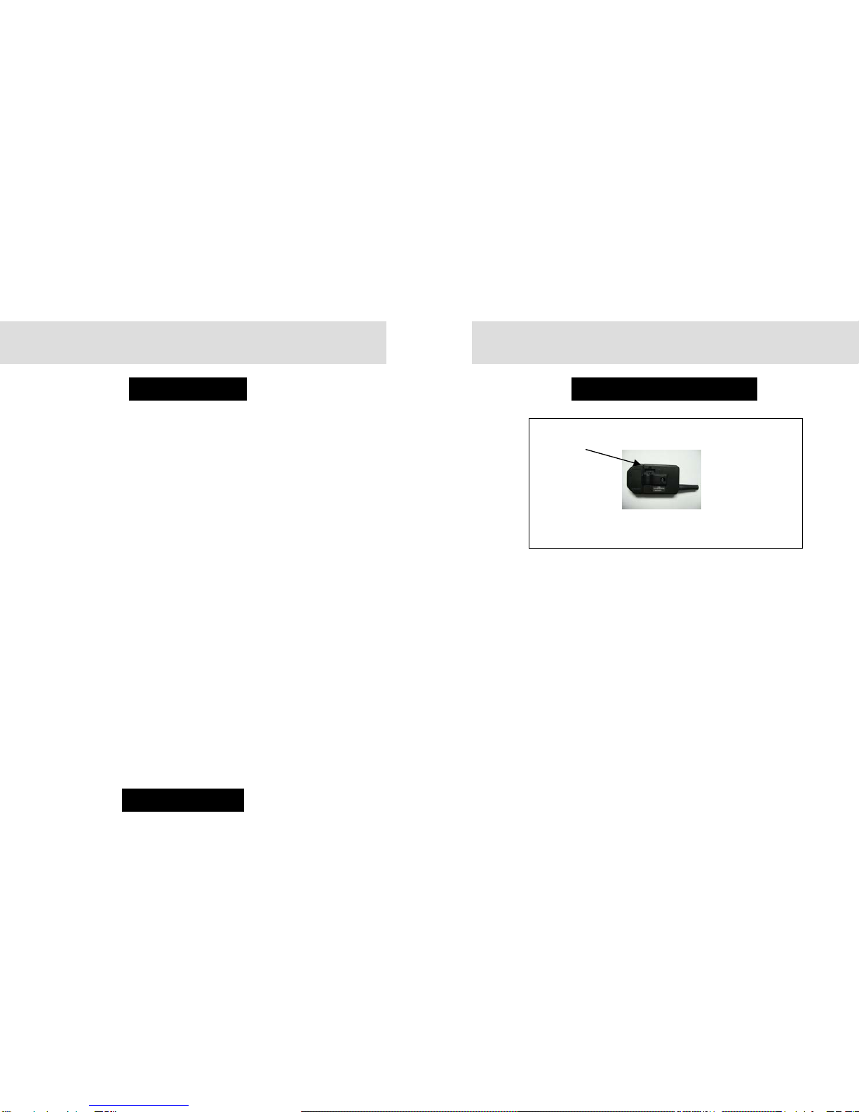
4. Connect Remote
Antenna • In plastic bag with keys
• MAINTENANCE Menu, scroll to
INS
• Depress Green ►button 5
seconds
• Unit will fill then mist for 5 minutes
or until stopped
• Confirm pump pressure (240 psi)
and insert plug (in bag)
• If zone valve installed, repeat for
INS2
6. Run Inspection
Cycle
• If PRO-CAP, EMP CAR (empty
cartridge) will flash. Program
PRO-CAP per enclosed
instructions
• If Smart Cap, no further action
required
7. Secure Smart Cap
or PRO-CAP and
Insert Bottle
IMPORTANT!!! Before inserting the cartridge into the Smart
Coupler, be sure the Smart Cap is securely screwed onto the
cartridge, but not overtorqued. The contents may leak out and
damage the unit if the cartridge threads are stripped or the Smart
Cap is cross-threaded.