AirPower APV-350 User manual

airpower europe GmbH -On the Hollow 7 - 53547 Dattenberg - Germany www.airpower-gmbh.com
AVP SMART Positioner
APV-350
Manual

airpower europe GmbH, Auf der Hohl 7, D-53547 Dattenberg, www.airpower-gmbh.com, [email protected]om
2
CONTENT
1. INFORMATION FOR THE OPERATOR .............................................................................................................. 3
1.1 CLASSIFICATION OF SAFETY INSTRUCTIONS ................................................................................................. 3
1.2 SAFETY AND WARNINGS ............................................................................................................................. 4
1.3 IMPROPER USE OR MODIFICATION OF THE DEVICE ..................................................................................... 4
1.4 INSTALLATION AND MAINTENANCE ............................................................................................................ 4
1.5 SCOPE OF DELIVERY .................................................................................................................................... 5
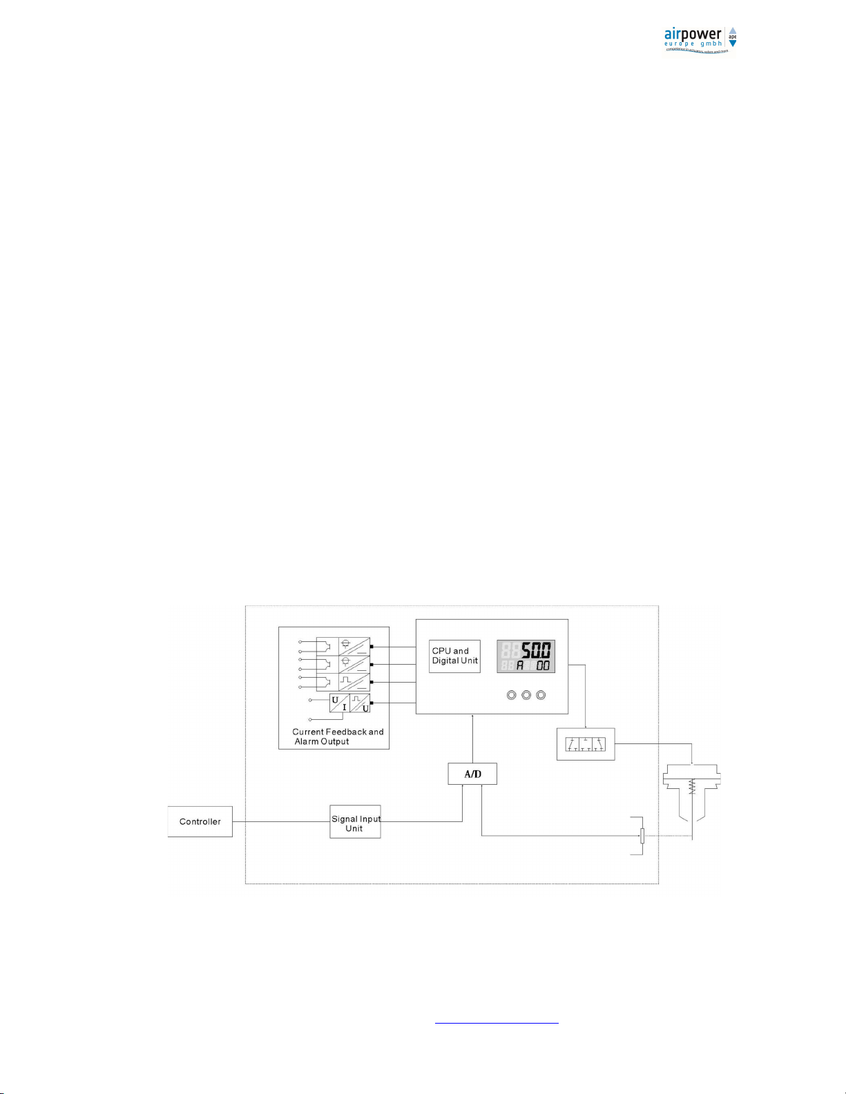
2. SUMMARY .................................................................................................................................................... 5
2.1 FUNCTIONS ................................................................................................................................................. 6
2.2 SPECIAL FEATURES ....................................................................................................................................... 6
2.3 INTEGRATED LIGHTNING PROTECTION ........................................................................................................ 6
3. TECHNICAL DATA ........................................................................................................................................... 7
4 INSTALLATION .............................................................................................................................................. 8
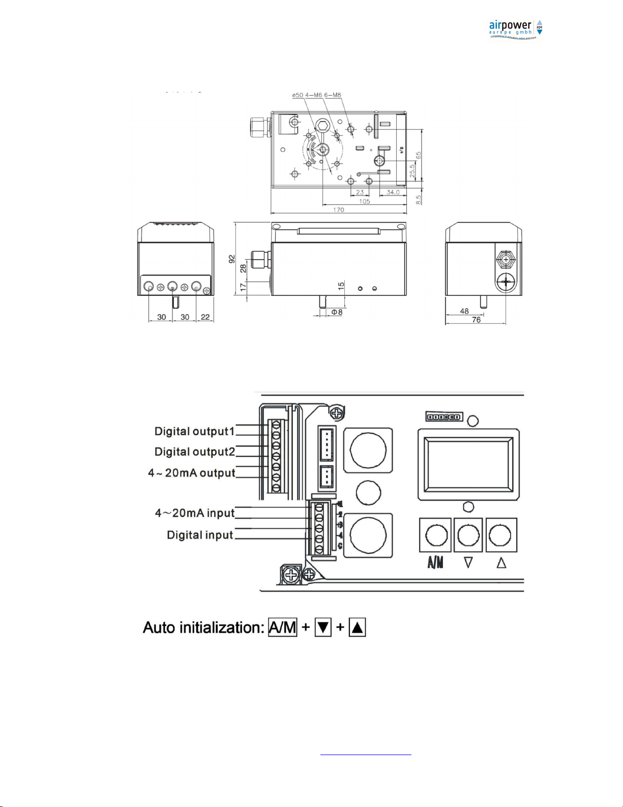
4.1 DIMENSIONS ............................................................................................................................................... 8
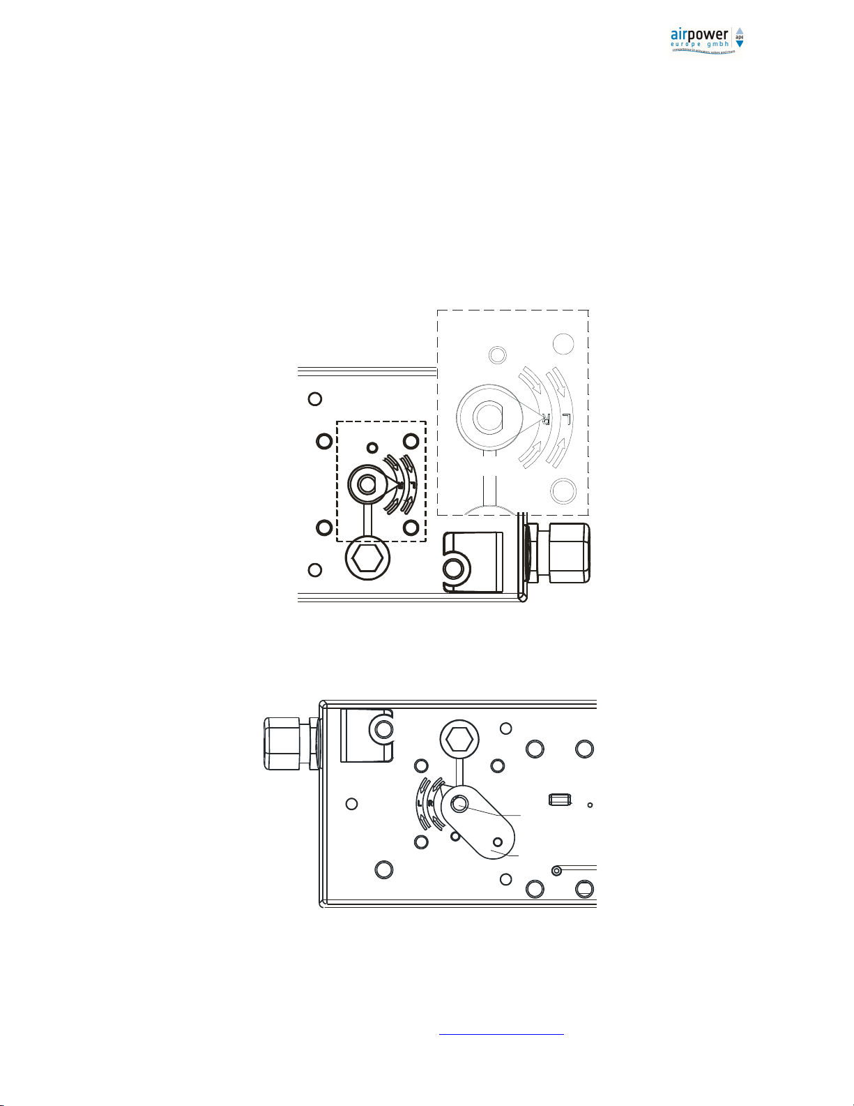
4.2 INSTALLATION ........................................................................................................................................... 9
5. OPERATION ................................................................................................................................................. 17
5.1 INTERFACE DESCRIPTION (USER INTERFACE) ........................................................................................... 17
5.1.1 DISPLAY .................................................................................................................................................. 17
5.1.2 BUTTONS................................................................................................................................................ 18
5.2 CONFIGURATION MODE ............................................................................................................................ 19
5.2.1 ENTERING TO CONFIGURATION MODE ................................................................................................... 19
5.2.2 CHOOSING A CONFIGURATION PARAMETER .......................................................................................... 19
5.2.3 CHANGING A PARAMETER ...................................................................................................................... 21
5.2.4 RESET USER PARAMETERS .................................................................................................................... 21
5.2.5 EXIT CONFIGURATION MODE ................................................................................................................. 21
5.3 INITIALIZATION .......................................................................................................................................... 21
5.3.1 EXAMINATION BEFORE INITIALIZATION .................................................................................................. 22
5.3.2 AUTOMATIC CALIBRATION ..................................................................................................................... 22
5.3.3 MANUAL CALIBRATION .......................................................................................................................... 23
5.4 DIAGNOSTIC MODE ................................................................................................................................... 24
5.4.1 SWITCHING TO DIAGNOSTIC MODE ........................................................................................................ 24
5.4.2 EXIT THE DIAGNOSTIC MODE ................................................................................................................. 24
5.4.3 DIAGNOSTIC PARAMETER....................................................................................................................... 24
5.5 ALARM ...................................................................................................................................................... 24
5.5.1 ZERO POINT OF POSITION SENSOR TOO LOW ......................................................................................... 24
5.5.2 END POINT OF THE POSITION SENSOR TOO HIGH................................................................................... 24
5.5.3 INITIALIZATION ERROR ........................................................................................................................... 25
5.5.4 MEASURING SPAN-RANGE IS INSUFFICIENT ........................................................................................... 25
5.5.5 USER CHARACTERISTICS SETTING ERROR ............................................................................................... 25

airpower europe GmbH, Auf der Hohl 7, D-53547 Dattenberg, www.airpower-gmbh.com, sales@airpower-gmbh.com
3
5.5.6 FEEDBACK OVER LIMITS ......................................................................................................................... 25
5.5.7 INPUT CURRENT OUT OF WORK RANGE ................................................................................................. 25
5.5.8 ACTUATOR ERROR .................................................................................................................................. 25
6 USER PARAMETER .......................................................................... FEHLER! TEXTMARKE NICHT DEFINIERT.
6.1 PARAMETER LIST ....................................................................................................................................... 26
6.2 PARAMETER .............................................................................................................................................. 28
7 FAULTS AND MAINTENANCE ....................................................................................................................... 34
7.1 TROUBLE SHOOTING.................................................................................................................................. 34
7.2 MAINTENANCE .......................................................................................................................................... 35
8 TRANSPORT AND STORAGE ........................................................................................................................ 35
9 ORDER - INFORMATION.............................................................................................................................. 36
9.1 PRODUCT DETAILS ..................................................................................................................................... 36
1. Information for the operator
This guide contains information you need to put the device into operation and use.
Read the instructions carefully before installation and commissioning. To ensure proper handling, familiarize yourself
with how the device works.
The manual is intended for people who mechanically mount, electrically connect, parameterize and put into
operation, as well as service technicians and maintenance technicians.
1.1 Classification of safety instructions
Make sure you are safe when installing, commissioning, and maintaining this instrument.
Please note the warning and warning texts.
Warning
Potentially dangerous situation!
Failure to do so can lead to serious injury or damage!
Caution
Dangerous situation! Observe the operating instructions!
Failure to do so may result in minor or moderate injuries!
Note
Important information for understanding the machine/plant or on optimized
operations!

airpower europe GmbH, Auf der Hohl 7, D-53547 Dattenberg, www.airpower-gmbh.com, sales@airpower-gmbh.com
4
1.2 Safety and Warnings
Note
1. This device has left the factory in a safety-related condition.
In order to maintain this condition and to ensure safe operation of the device,
follow these instructions and all safety-relevant information.
2. This device is built according to state-of-the-art and approved safety regulations.
3. The device manufacturer reserves the right to change technical parameters without prior notice.
4. The permissible temperature during storage transport and operation must be adhered to.
5. The device must be connected according to the connection diagram in the manual.
6. Observe the notes and icons on the device. Do not remove any hints and icons from the device. Always
keep the notes and symbols in a fully readable state.
7. Appropriate markings shall be affixed to the type plates of equipment used in potentially explosive
atmospheres. When operating equipment in an explosion-prone area, the relevant regulations must be
complied with. The installation specifications, connection parameters and safety instructions of the explosion
flame protection document must be adhered to.
1.3 Improper use or modification of the device
Note
1. Improper use of the device may pose a danger to the life and limb of the user or to third parties, or cause
damage to the machine and other material objects.
2. Change the device only as described in the device instructions. In the event of non-compliance, the
manufacturer's warranty and product liability expire.
1.4 Installation and maintenance measures
Note
1. Installation, commissioning, operation, maintenance and repair of the equipment requires special
knowledge and should only be carried out by qualified personnel.
2. For the installation of this device, the operator must read the user manual and follow the rules.
3. Before carrying out maintenance work, the device must be switched off without power.
In addition, always switch off the compressed air supply before dissolving the air connections.
4. The device must not be modified or repaired unless the user follows the instructions in the manual.
5. Repairs that are not described in the supplied operating instructions may only be carried out directly by the
manufacturer or by the service organization.
6. If welding work is carried out near the device, the grounding of the welding equipment shall not be carried
out by this device.

airpower europe GmbH, Auf der Hohl 7, D-53547 Dattenberg, www.airpower-gmbh.com, sales@airpower-gmbh.com
5
1.5 Scope of delivery
AVP-350 SMART positioner
User Manual (PDF)
Quick-start manual (PDF)
Accessories / spare parts (optional)
2.
Summary
An AVP-350 SMART positioner is a two-wire (4 ... 20 mA) device of airpower europe GmbH. The positioner is a control accessory of
the pneumatic actuator for valves. It is widely used in automatic control systems in the chemical industry,
the energy industry, the metallurgy industry, the pulp and paper industry and many other sectors.
The AVP-350 receives the analog 4 ... 20 mA signal for the valve adjustment from the control system (PLS). This setting value is
converted from an analog to digital converter and serves as input to the CPU. At the same time, the AVP-350 receives the actual
value for the valve position of position sensors. The two signals are compared by the AVP-350 software with the aim of controlling
the inlet and outlet of the pneumatic actuator and reaching the setpoint for the position of the valve (see Figure 2-1)
The AVP-350 is based on microprocessor technology. It can easily compensate for mechanical influences of the valve and the
actuator, such as friction, and improve the response speed of the valve, which allows the desired position to be reached quickly
and accurately. Optionally, the AVP-350 can also directly access the HART network, enabling an extended exchange of information
between the control system (PLS) and the positioner.
The AVP-350 SMART position controller complies with the IEC60079-0:2017- Hazardous areas - Part 0: Equipment - General
requirements and Explosive atmospheres - Part 11: Equipment protection by intrinsically safety "Ex i".
The AVP-350 SMART position controller is therefore also suitable for use in the vicinity of combustible dusts – Part 11: Protection
by intrinsic safety “ID”.
Fig.2-1 AVP-350 Positioner principle

airpower europe GmbH, Auf der Hohl 7, D-53547 Dattenberg, www.airpower-gmbh.com, sales@airpower-gmbh.com
6
2.1 Functions
Self-adjustment function: automatic calibration of zero point and span of the valve
Optimization of control parameters to increase control accuracy
Configuration function: valve characteristic curve, action mode, dead band, stroke range, shut-off value and alarm events
Self-diagnosis function: display of the value of the input current, runtime, dead band
Fault mode function: fail safe or fail freeze
Communication: HART communication protocol (optional)
Position feedback function: 4 ... 20 mA (actual value) - optional
2.2 Special features
Positioning precision: 0,5 % FS
Small and compact design, modular design
Automatic initialization, automatic diagnostics, valve characteristic
Fewer mechanical parts, high stability against vibrations
Local or remote parameter configuration
Low power consumption and minimum air consumption in static state, resulting in lower operating costs
Use of the 4 ... 20 mA standard signal (setpoint)
Integrated surge
2.3 Integrated lightning protection (optional)
Modern position controllers become smarter, smarter and use BUS technologies for communication as technology advances.
Therefore, it is inevitable that electronic components will be used that are more sensitive to overvoltage. In the event of
lightning, these components would be quickly damaged, which can cause the positioner to fail. Many positioners do not have a
special protection function and are therefore prone to damage due to overvoltage or lightning.
One solution to this problem is the integrated discharge circuit in the AVP-350, which protects the positioner from overvoltage.
Note
1. The lightning protection function is offered as an option.
2. The grounding must be carried out in accordance with the relevant standards, before installing the
device.

airpower europe GmbH, Auf der Hohl 7, D-53547 Dattenberg, www.airpower-gmbh.com, [email protected]om
7
3. Technical data
Pneumatics
Air 1.4 to 7 bar - 0.14 to 0.7 MPa
Valve leakage 0.6 l/h
Air consumption
in stable condition 36 l/h
Control air - quality
According to ISO 8573-1:2010; Size and density of solid particles Class 4
Pressure dew point Class 4 (at least 10 K below ambient temperature)
Oil content Class 4
Entrance/
Output
Actuator Single acting, double acting
Travel Range Angle of rotation:30° - 105o
Input 4 ... 20mA/DC, min. Input current: >3.8mA, split range
Start and end point adjustable
Feedback output 4 ... 20mA DC
optional
Digital input 1 Potential-free contact
Digital output 24 V, 2-A range switch: 2 channels,
electronic switch: 2 channels
Piezo-valves switching time Average failure-free time: >2 billion cycles
Output Characteristic Linear, 1:30, 30:1, custom (20 points)
Communication HART (optional)
Display
LCD 2×7 digits, dimensions: 22×38mm
Pressure gauge display of input and output pressure (optional)
Operation
Self tuning Automatic calibration of zero point and span, dead band
Self diagnostic Display of the value of the input current, runtime, dead band, etc.
Manually 3 buttons on the front
Accuracy
Dead band 0.1 to 10% adjustable
Linearity ≤±0,5% FS
Hysteresis ≤0,5% FS
Environment
Temperature Standard: -40° to max. +80°C
Eigensicher: T6 (-35C - 40C), T5 (-35C - 55C), Q4 (-35 ... 80) C
Relative humidity 5 to 95% RH
Vibrations resistance 15 to 150Hz x 2g
IP protection class IP65
Weight 2 .0 kg
Casing
Dimension 170×96×92mm
Casing material Aluminum alloy

airpower europe GmbH, Auf der Hohl 7, D-53547 Dattenberg, www.airpower-gmbh.com, sales@airpower-gmbh.com
8
4 Installation
4.1 Dimensions
Fig. 4-1 AVP-350 Dimensions
Fig. 4-2

airpower europe GmbH, Auf der Hohl 7, D-53547 Dattenberg, www.airpower-gmbh.com, [email protected]om
9
4.2 Commissioning / Installation
4.2.1 General
Fig. 4-2 shows the view of the positioner with the lid open and the terminal strip.
Fig. 4-3 shows the feedback indicator of the positioner and the arrow that shows the rotational area of the
indicator. The solid line shows the middle position of the indicator (without initialization, the LCD feedback value
should be around 50.0, and the lower line indicates NOINIT).
The two dotted lines show the boundary position of the feedback rotating range in normal use. The position sensor
inside is already preset.
Fig. 4-4 shows the positioner assembled on a rotary actuator.
Fig. 4-3
Fig. 4-4
Lim it 1
Lim it 2
f
ee dba ck sh aft
f
ee dba ck le ver

airpower europe GmbH, Auf der Hohl 7, D-53547 Dattenberg, www.airpower-gmbh.com, [email protected]om
10
4.2.2 Installation on a rotary actuator
Parts overview: Note: item 4+5+8+9 = “Adapter”
Number Lot Naming Specification
1 4 Washer D6
2 4 Spring washer D6
3 4 Screw M6×10
4 1 Holder (positioner)
5 1 Screw M4×5
6 1 Mounting bracket
7 2 Mounting angle
8 1 Picker (actuator)
9 1 Hexagon screw M6
10 4 Fixing screw (actuator) - Hexagon M5×10
11 4 Spring washer D5
12 4 Washer D5
13 4 Fixing screw (brackets/angle) M5×10
14 4 Spring washer D5
15 4 Washer D5
Fig. 4-5
6
4
5
3
1
2
7
89
10
11
12

airpower europe GmbH, Auf der Hohl 7, D-53547 Dattenberg, www.airpower-gmbh.com, sales@airpower-gmbh.com
11
Fig.4-6 Installation on a rotary actuator
The installation steps are as follows (Fig. 4-5/ 4-6):
- Attach the mounting angle (6) to the positioner using hexagon screws (3) and washers (1).
- Attach the holder (regulator) (4)) to the shaft of the controller by means of a screw (5).
- Mount the mounting brackets (7) on the rotary actuator with the fastening screws (10) and washers (12).
- With the screw (9) you attach the appropriate picker (8) to the sprocket of the rotary actuator.
- Carefully place the positioner on the pneumatic rotary actuator. The pin of the taker (regulator (4) must be located in the opening
of the U-shaped co-driver of the actuator (8)).
- Adjust the height of the positioner, attach the screw to the pin of the holder (4)) and fix the positioner with the hexagon screw
(13), spring discs (14) and washers (15).
- Adjust the angle of rotation of the adapter (part no. 4+5+8+9). The angle must be between 45° ... 52°.
Note
1
、
Do not cover the exhaust with the mounting kit!
2. The angle of rotation of the contactor should meet the requirements of the rotary actuator.
4.3 Pneumatic connection
The pneumatic connector is located on the right side of the positioner. The positioner offers two connection types: G1/4 or NPT
1/4 (see order data). The specific type is indicated on the casing.
Select the pipe to be connected accordingly.
13 1415

airpower europe GmbH, Auf der Hohl 7, D-53547 Dattenberg, www.airpower-gmbh.com, [email protected]om
12
Fig. 4-7 Pneumatic connection
Version single-acting - with springs version double-acting
Steps to install:
Connect the output of the AVP-350 Intelligent positioner to the input of the pneumatic rotary actuator. according to Fig. 4-7.
Air supply requirements:
1.
Depending on the rotary actuator, the air pressure must be between 1.4 ... 7 bar.
2.
The air supplied must be clean, dry air, free of oil, water or other liquids.
3.
The air supplied must not have a significant proportion of corrosive substances, vapour or solvents.
4.
The amount of solid particles in the air supplied shall not exceed 0.1 g/m3,
particle penetration do not exceed 60 microns. (Class 4)
5.
The oil content must be less than 1.0 mg/m3.
6.
The dew point of the air at working pressure must be at least 10 K below the ambient temperature.
4.4 Electrical connection
4.4.1 Basic requirements
Electrical connections must be carried out strictly according to the connection plan and can be easily fastened. The cable gland
corresponds to the protection class IP65. The diameter of the signal cable must be at least 8mm.
The casing cover shall be fastened in such a way that the IP protection level is not lowered.
An intrinsically safe positioner must be combined with the associated equipment that passed the explosion-proof certification in
order to form an intrinsically safe explosion-proof system for use in potentially explosive atmospheres. The wiring of the system
must meet the requirements of the positioner and the associated equipment /intrinsically safe equipment, and the terminals must
be connected correctly.
Requirement for staff
During installation, commissioning, operation, maintenance and repair, the operator must
O U T
1
O U T
IN IN
O U T
2
WARNING
It is essential to avoid leakage of the connection. Use soapy water to check the air
tightness of the connection interfaces.

airpower europe GmbH, Auf der Hohl 7, D-53547 Dattenberg, www.airpower-gmbh.com, [email protected]om
13
- have read and understood the user manual - be authorized by the plant operator
- be an electrician
- observe the usual regulations:
IEC 61241-11:2005, Electrical equipment for use in combustible dust - Part 11: Protection by intrinsically safety
IEC 60079-19:2019 Explosive Atmospheres - Part 19: Repair, Overhaul and Recovery of Equipment
IEC 60079-14:2013 Explosive Atmospheres - Part 14: Design, Selection and Installation of Electrical Systems
IEC 60079-17:2013 Explosive Atmospheres - Part 17: Inspection and Maintenance of Electrical Installations
IEC 60529-2013 Enclosure protection levels (IP code)
4.4.2 Connection of an intrinsically safe position controller
4.4.2.1 Electrical input connection (Fig. 4-8)
Type: 2-wire power supply
Input signal: 4 ... 20 mA
Min. working current: 3.8mA / DC
Input impedance: 455 Ω @20mA (without HART)575 Ω @20mA (with HART)
Non-hazardous area Zone 0, 1 or 2
Fig. 4-8 Electrical input connection
4.4.2.2 Electrical connection - digital output (binary) ( (Fig.4-9)
Working voltage: <15.5V DC
Output:
Digital feedback module Output
Signal status "high" (Trigger) ≥2.1 mA
1
3
2
4
+
-
digital input
p ositione r
4~20mA DC
H A R T
Commu-
nicator
Sa fety b a rrier
D C S
I,V A
E
Intrinsically safe
parameter
(1+ 2-): Barrier requirement:
Ui =28V
DC
Ii =93mA
Pi =0.65W
Ci =18n F
Li ≈0
Uo ≤15.5V DC
Io ≤25mA
Po ≤96.9 mW

airpower europe GmbH, Auf der Hohl 7, D-53547 Dattenberg, www.airpower-gmbh.com, [email protected]om
14
Signal status "low" (Trigger) ≤1.2 mA
Intrinsically safe parameter (21+ ~22-),(31+ ~32-): Barrier requirement:
Ui =15,5V DC
Ii =25mA
Pi =96,9 mW
Ci ≈ 0
Li ≈ 0
Uo ≤15.5V DC
Io ≤25mA
Po ≤96.9 mW
Hazardous Area zone 0,1 or 2, Non-hazardous Area
Fig.4-9 electrical connection of the
digital output module
4.4.2.3 Electrical connection of the analog feedback module (Fig.4-10)
Feedback signal type : 2-wire-system, 4 … 20 mA /
DC
Temperature influence: ≤100ppm/°C
Working area: 3.6 ... 20.5 mA DC
Precision: ≤0.1%
Working voltage: 12 … 28V DC
Intrinsically safe parameter (11 + ~12-):
Barrier requirement:
Ui =28V DC
Ii =93mA
Pi =0.65 W
Ci =10nF
Li ≈ 0
Uo ≤28V DC
Io ≤93mA
Po ≤0.65W
D C S
I,V
2K 21
22
31
32
2K
_
_
+
+
Dig ita l outp ut m od ule
Sa fety b a rrie r
D C S
I,V

airpower europe GmbH, Auf der Hohl 7, D-53547 Dattenberg, www.airpower-gmbh.com, [email protected]om
15
Hazardous Area zone 0, Zone 1 or Zone 2 non-hazardous areas
Fig.4-10
Electronic connection of the analog feedback output module
4.4.3 Connection of a Non-intrinsically safe position controller
4.4.3.1 Electrical input (Fig. 4-11)
Type: 2-wire power supply
Input signal: 4 ... 20 mA
Min. Working current: 3.8mA / DC
Input impedance: 455 Ω @20mA (without HART) 575Ω @20mA (with HART)
Fig. 4-7 electric input connection
4.4.3.2 Electrical connection of the digital output (binary) (Fig.4-12)
Working voltage:12 … 35V DC
Output:
Digital output module (binary) Output
Signal status "high" (Trigger) ≥2.1 mA
Signal status "low" (Trigger) ≤1.2 mA
11
2K
12
12~28V
_
_+
+
Ana log fe e d b a c k m od ule
D C S
I,V
Sa fety b a rrier
1
3
2
4
+
-
digital input
p ositione r
4~20mA DC
H A R T
Commu-
nicator
Sig na l isola tor
DCS A
E

airpower europe GmbH, Auf der Hohl 7, D-53547 Dattenberg, www.airpower-gmbh.com, [email protected]om
16
Fig.4-12
electrical connection of digital (binary) output module
4.4.3.3 Electrical connection of the position feedback module (Fig.4-13)
Feedback signal type: 2-wire-system, 4 … 20 mA
DC
Temperature influence: ≤100ppm/°C
Working area: 3.6 ... 20.5 mA / DC
Precision: ≤0.1%
Working voltage: 12 ... 30V DC (terminal 11+12)
Fig.4-13
Electronic connection of the position feedback module
DCS
2K 21
22
31
32
2K
_
_
+
+
Dig ita l outp ut m od ule
Signa l isolator
DCS
11
2K
12
12~30V
_
_+
+
Analo g fe ed bac k m o dule
D C S
Sig na l isola tor

airpower europe GmbH, Auf der Hohl 7, D-53547 Dattenberg, www.airpower-gmbh.com, sales@airpower-gmbh.com
17
5.
Operation
5.1 Interface description (Fig. 5-1 user interface)
Fig 5-1
5.1.1 Display
The LCD display is divided into 2 lines.
•
Normal:
The first line shows the position.
The 2nd line from left to right shows "direction of the valve action",
the “state of the action" and the "setpoint".
•
In the menu status of the configuration:
The first row shows the parameter value.
The second line from left to right shows "parameter number" and
"name of parameter”.
Note
When the positioner is used in areas below -10°C,
the LCD display becomes sluggish
and the display refresh rate decreases significantly.

airpower europe GmbH, Auf der Hohl 7, D-53547 Dattenberg, www.airpower-gmbh.com, sales@airpower-gmbh.com
18
5.1.2 Buttons
The positioner has three buttons. See Fig.5-1:
Operating mode switch "ENTER"
Down "DOWN"
Up "UP"
In normal operation:
Press the A/M button to switch between automatic and manual operation.
Line 2 indicates "A" for automatic; "M" for manual operation.
In manual operation:
Hold down, opening angle of the valve is increased
at the same time, hold down and the opening angle increases rapidly.
In contrast, when you press first, the opening angle is reduced
Then hold down at the same time, the opening angle decreases quickly.
Note

airpower europe GmbH, Auf der Hohl 7, D-53547 Dattenberg, www.airpower-gmbh.com, sales@airpower-gmbh.com
19
1. Automatic control mode: 2nd LCD line shows "A"
2. Manual control mode: 2nd LCD line shows "M"
3. Diagnostic mode: 2nd LCD line shows " SENS "
5.2 Configuration mode
5.2.1 Switching to Configuration Mode
In normal mode, press A/M key for at least 3 seconds to enter configuration mode.
5.2.2 Choosing a Configuration Parameter
The parameters are divided into 4 different groups: P1, P2, P3 and P4.
Menu P1 for configuring basic parameters, including initialization,
show the unit, type of rotary actuator, running range, dead band, etc.
Menu P2 for configuring input settings, including direction, auxiliary control, ramp settings, output
settings
Menu P3 for configuring the relative valve parameters, including
the run-limiting control and the running directions
Menu P4 for configuring the function module, including safety valve settings,
In-/output settings for switching function, current output settings, etc.
In configuration mode, the user selects parameter group P1, P2, P3, or P4.

airpower europe GmbH, Auf der Hohl 7, D-53547 Dattenberg, www.airpower-gmbh.com, sales@airpower-gmbh.com
20
Fig.5-2 Selecting a parameter group
Within this parameter group, the user can select the parameter:
Press the button to scroll through the menu upwards
Press the button to scroll down the menu
Here the contents of the parameters are displayed:
Fig.5-3
Configuring a parameter
The first two digits of the second line show the parameter index number, and letters on the right show
N
Table of contents
Popular Valve Positioner manuals by other brands

Parker
Parker MSR Series User's information guide

Power-Genex
Power-Genex SSL Series quick start guide

Spirax Sarco
Spirax Sarco SP7-10 Installation and maintenance instructions

GEM
GEM 533 operating instructions

Will Burt
Will Burt PositionIt PI-35 Operator's manual

Festo
Festo CMSX-P-S-C-U-F1-D-130-A operating instructions