AirTies Air 5450 User manual

User
manual
300 Mbps Wireless ADSL2+ Router
Air 5450
Гарантия 3 года
CD простой установки
Поддержка 7/24
8 800 100 02 80
8 800 507 44 40

2
1 INTRODUCTION 4
1.1 Minimum System Requirements 4
1.2 Package Contents 4
1.3 Front Panel 4
1.4 Back Panel 5
1.5 Main Features 5
2 INSTALLATION 6
2 1.Basic Cabling Procedure 6
3 ADSL SETTINGS 6
3.1 ADSL Status and Statistics 6
3.2 ADSL setup 6
3.3 DNS setup 7
3.4 Mode setup 7
4 WIRELESS SETTINGS 7
4.1 Setting up awireless connection 7
4.2 Wireless Network Settings 8
4.3 Wireless Security Settings 8
4.3.1 WPA2 Security Settings 8
4.3.2 WPA Security Settings 9
4.3.3 WEP Security Settings 9
4.4 MAC Filtering 10
4.5 AirTies Mesh settings 10
5 ADVANCED SETTINGS 11
5.1 HOMEPAGE 12
5.2 LAN 12
5.2.1 IP and DHCP Settings 12
5.2.2 LAN Clients 13
5.3 FIREWALL settings 14
5.3.1 Access control 14
5.3.2 MAC address ltering 15
5.3.3 URL lters 15
5.3.4 Anti-DoS 15
5.4 NAT 16
Contents Manual Overview 3
Safety and Maintenance 3
5.4.1 Port Forwarding 16
5.4.2 DMZ 17
5.5 Routing 17
5.5.1 Static Routing 17
5.5.2 Dynamic Routing 17
5.6 MANAGEMENT 18
5.6.1 Password Settings 18
5.6.2 Remote Management 18
5.6.3 TR-069 Settings 19
5.7 DDNS 20
5.7.1 DDNS Settings 20
5.8 Tools 20
5.8.1 Firmware Upgrade 21
5.8.2 Time Settings 21
5.9 REPORTS 21
5.9.1 System Logs 21
5.9.2 Log Settings 22
6TECHNICAL PROPERTIES 22
7PHYSICAL CHARACTERISTICS 22

3
This manual guides you through the steps necessary for setting up and configu-
ring your AirTies device. Please read this manual carefully before beginning the
installation process.
The Warranty does not cover failure or damage as a result of not following the ins-
tructions in the manual. AirTies will not be held responsible in such circumstances.
The User Manual is an important resource you can refer to for safe and proper use
of your device. Please retain it for future reference.
• In order to prevent damage to your device, be sure to keep it in its original box
during transportation.
• The device must be used solely with its original power adapter.
• Do not insert a PSTN (phone) plug into the LAN port.
• If you encounter any problems, do not open or disassemble the device. Call
AirTies Technical Support.
• In order to prevent electric shock, do not operate the device in wet or damp
areas.
• In the event of a gas leak, do not use the device. Do not turn the device on or o.
Do not plug or unplug the power cord.
• Avoid using the device in dusty environments. If dust buildup should occur, use a
dry cloth to remove the dust.
• To clean the exterior of the device use a dry cloth. Do not attempt to clean the
interior. There are no user serviceable components inside.
• For information regarding the installation and configuration of the device
consult the remainder of this manual.
• Remove all protective plastic on the top and bottom of your device before you
start using it.
• The average usage life of the device is 7 years as determined by the Authority of
Industry and Trade.
This manual has been prepared by AirTies Wireless Networks Corporation. All rights reserved.
Manual Overview
Safety and
Maintenance

4
LED Light Status
Blue AirTies router is “ON”.
O AirTies router is “OFF”..
Red ADSL connection
established and active
Red Flashing An ADSL connection is
being negotiated
O No ADSL connection
Red Internet connection
established and active
O No Internet connection
Red LAN connection is
ready to use
Red Flashing LAN connection
active. There is data
exchange.
O LAN connection is
not active
Red Wireless connection is
ready to use
Red Flashing Wireless connection
active. There is data
exchange.
O Wireless connection is
disabled
Red USB connection establis
hed
Red ashingι USB connection active.
There is data exchange.
O No USB connection
• For installation and configuration: a computer that has an Ethernet interface
or wireless capability that is compatible with 802.11b/g/n standards, and is
running any version of Windows, UNIX, Linux or Mac Operating Systems
• For the AirTies ADSL Utility: 32 bit Windows (98/ME/2000/XP/Vista)
• The router does not need to be connected to a computer during normal
operation.
With Air 5450 which uses 802.11n technology, transfer wireless data, watch videos
or upload your pictures to the Internet at speeds of up to 300Mbps. Backward
compatible with the wireless 802.11b/g devices, the Air 5450 provides 6 times
faster wireless communications compared to earlier technologies. Dead spots
and packet losses on your wireless network becomes a thing of the past with the
MIMO (Multiple Input Multiple Output) technology and the advanced error recovery
system contained in the 802.11n standard.
1 INTRODUCTION
1.1 Minimum Sys-
tem Requirements
1.3 Front Panel
1. Air 5450 300Mbps Wireless ADSL2+ Router
2. Power adapter
3. Ethernet cable
4. Telephone cables (1 long, 1 short)
5. Splitter
6. Easy Setup CD
7. Quick Installation Guide
8. Warranty Card
1.2 Package
Contents
1
8
6
2 3 4
5
ETHERNET
3 Warranty
Card
Wirelesslife
7/24 people support
+90 212 444 0 239
Three year warranty
Lifetime enjoyment
One touch setup
Simple & easy to use
PSTN
Quick Installation Guide
300Mbps Wireless ADSL2+ Router
Air 5450
Wirelesslife
7

5
1.4 Back Panel • All-in-one solution: ADSL2+ Router, 300Mbps wireless access point, Firewall, 4
Ethernet ports
• High speed wireless: 300 Mbps wireless access point compliant with the
802.11n (Draft2.0) standard**
• ADSL2+ technology for high speed Internet (24Mbps download/ 4Mbps
upload)
• Wireless Access range and Mesh Technology: AirTies Mesh Technology
support for extending coverage area by using additional AirTies wireless access
point devices.
• IPTV-ready!!: The Air 5450, with its IP QoS, VLAN, PVC-Port mapping and IGMP
support, is ready for the newest, state of the art services oered over the
Internet such as IPTV*
• USB Plug and Share feature gives you printer and file sharing capability throug-
hout your entire network from a single point*
• Advanced Wireless Security: WPA2-PSK, WPA2-802.1x, WPA-PSK,
WPA-802.1x, WEP wireless encryption standards support
• Automatic Wireless Security configuration: The AirTies ADSL Utility automati-
cally configures wireless security settings for the router and the PC that is used
for setup.
• Firewall: Advanced anti-DoS SPI Firewall; MAC, URL and IP address based
filtering for Internet access
• Easy installation with animated instructions with the Easy Setup CD
• Automatic Firmware Upgrade: Automatic firmware upgrade capability with the
AirTies ADSL Utility. It is important to use the latest firmware to get the best
possible performance out of your router.
• ADSL Usage Monitor: Especially useful for limited quota ADSL subscribers,
making it easy to track monthly total download and upload amounts
• Router: Advanced router with DHCP server, NAT, NAPT, DMZ, VLAN*, RIPv1/v2
support
• 8 Channel PVC support
• Robust against voltage uctuations: Specially designed to withstand wide
voltage uctuations
• Remote management: Web and TR-069 support for remote management
• 7/24 AirTies Call Center and Technical Support (engineering support by the
AirTies R&D team when needed)
• 3 year extended warranty
• Designed to be compatible with your local ADSL infrastructure
*Features to be added with a firmware upgrade
** 11.N Ready
1.5 Main Features
ADSL ADSL line port, connects to the MODEM port of the
Splitter
Ethernet 4 - 1 Ethernet ports
Reset Button to reset your device to default factory settings
USB USB port
ON/OFF Button to turn your device on and o
15V 15V power port, connects to the power adapter

6
2 INSTALLATION
2 1.Basic Cabling
Procedure
53
4
6
1
2
Connecting the Cables
All wiring and configuration procedures explained in this document are also
demonstrated with the animation that starts when you run the Air 5450 Easy Setup
CD. Please run the Easy Setup CD first.
1- Connect the power adapter provided to the power port of your router and plug
it into the wall outlet.
2- Turn on the Air 5450 by setting the On/O switch to the “|” position.
3- Using the short telephone cable provided, connect the Modem port of the
Splitter to the ADSL port of your router.
4- Connect the main phone line to the Line port of the Splitter. If the main phone
line is currently connected to your phone, first disconnect it from your phone,
and then connect it to the Line port of the Splitter.
5- Using the long telephone cable provided, connect your phone to the Phone port
of the Splitter.
6- Using the Ethernet cable provided in the box, connect your PC to any of the four
Ethernet ports of your router.
3 ADSL SETTINGS
2. To enter your ADSL settings click the “Edit” button in this table. The “PVC
Settings” screen will come up.
3. On the “PVC Settings” screen, enter the user name and password given to you
by your ADSL service provider in the “ADSL Username” and “ADSL Password”
fields, respectively. Click “Save” to complete your ADSL setup.
When you click “ADSL” on the main menu of your router’s Web interface, the “ADSL
Status/Statistics” page will come up. Here, you can see detailed information about
your router’s ADSL connection and upstream/ downstream data rates. You can also
check the status of your current PVC connection.
3.1 ADSL Status and
Statistics
When you click “ADSL” on the left menu of your router’s Web interface, you will
see “ADSL Setup” as the first sub menu. Go to “ADSL Setup” to configure your
router’s ADSL settings and follow the steps below:
1. When you click on the “ADSL Setup” submenu, a table showing your default
PVC settings will be displayed.
3.2 ADSL setup

7
DNS (Domain Name Service) is an Internet service that translates domain names
into IP addresses. For example, when you try to go to the www.airties.com address,
first your Internet service provider’s DNS will try to translate it to the corresponding
IP address. The DNS system is, in fact, its own network. If one DNS server doesn’t
know how to translate a particular domain name, it asks another one, and so on, all
the way to the main InterNIC DNS server, until the correct address is returned. Most
service providers will provide Domain Name services for security and speed.
Go to “DNS Setup” under the “ADSL” menu of your router’s Web interface. On the
screen that comes up, you will see three DNS fields. The first two are your service
provider’s DNS addresses and cannot be changed. If you prefer to use a dierent
DNS server, enter its IP address in the “DNS 3” field.
3.3 DNS setup
3.4 Mode setup Dierent Internet service providers may dier in terms of modes of the ADSL servi-
ce they oer. Some only provide basic ADSL service, while others provide dierent
modes of ADSL such as ADSL2, ADLS2+, etc..
Your router supports multiple ADSL modes. You can see the ADSL modes suppor-
ted and change settings by going to “Mode Setup” under the “ADSL” menu of your
router’s Web interface. All ADSL modes are enabled by default. On this screen, you
can disable/enable the modes as you choose. Click “Save” when you are done with
the mode setup.
Important:Please choose your Annex Type as Annex A (PSTN) or Annex B (ISDN)
according to your line type on Mode Setup screen
With the 802.11N standard, you can setup a wireless network with data rates of
up to 300Mbps allowing you to share files between PCs at very high speeds. Your
router is backward compatible with the 802.11b/g standards and can also work
with 802.11b/g devices without aecting the performance of 802.11N devices.
By using clients and access points that support 802.11n, you can achieve wireless
transfer rates of up to 300 Mbps. Additionally, the MIMO mode supported by the
802.11n standard gives you a much broader wireless range than 802.11b/g
devices do.
4 WIRELESS
SETTINGS
Your router has Wireless networking enabled by default. No additional router
configuration is needed for your wireless computers to access the Internet. It is
recommended that you configure wireless security as explained in the sections
that follow.
In order to connect your laptop to the AirTies router wirelessly:
Go to Start-Settings-Network Connections- Wireless Network Connection-
View Wireless Networks. On the “Wireless Network Connection” screen, select
the wireless network named AIRTIES_ 5450 and click “Connect”.
4.1 Setting up a
wireless connection
AIRTIES_ Air5450

8
4.2 Wireless
Network Settings
When you click the “WIRELESS” menu of your router’s Web interface, you will be in
the “Wireless Connections” screen that lists all the wireless clients connected to
the router. You can block the access of any client to your wireless network by using
the “MAC Filtering” option.
To configure your wireless network settings, go to “Wireless Setup” under the
“WIRELESS” menu. On the screen that comes up you can see whether wireless
networking is enabled or not.
Wireless settings are in two dierent categories: General wireless settings for
your router and settings for your particular wireless network (SSID).
• “Frequency” shows the main frequency band your router is using. Depending
on the frequencies supported it could be 2.4GHz or 5GHZ.
• “Mode” shows the IEEE 802.11 mode actively used by your router. The default
mode is 802.11b/g, supporting both 802.11b and 802.11g devices.
• “Channel” field allows you to choose the channel your router will broadcast in.
It is recommended that you choose one of channels 1,6, or 11.
• “Power” displays the total transmitted power from the device
• “Rate” shows the highest wireless data transfer rate supported by your router.
It is set to “Auto” by default. This allows for automatic adjustment of data
transfer rate based on distance and signal quality.
AIRTIES_ Air5450
AIRTIES_ Air5450
It is not necessary to configure wireless security to enable wireless communication.
However, for your data security, it is recommended that you choose one of the
security protocols described below that best fits your needs.
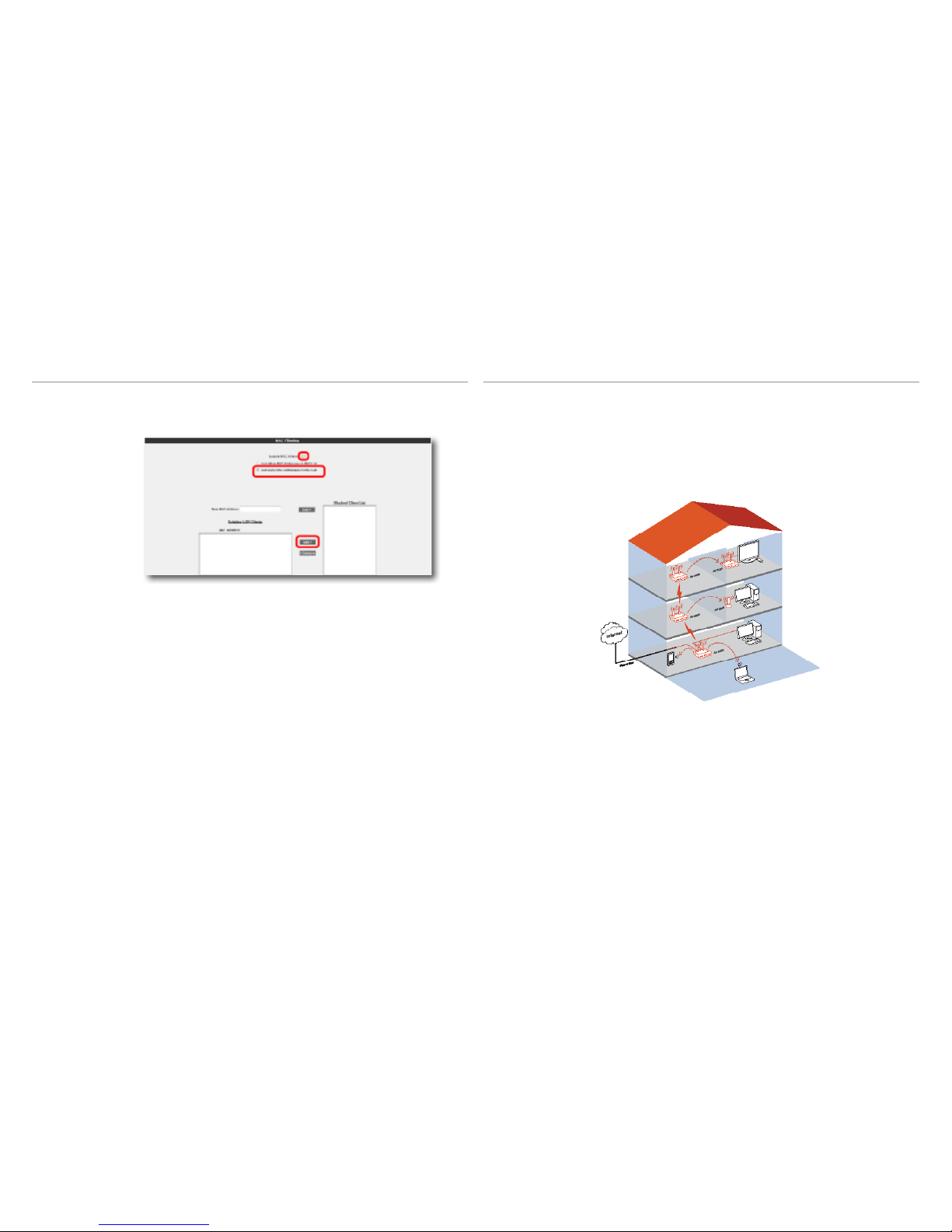
WPA2, WPA, and WEP are wireless encryption protocols used to encrypt the data
traic within the wireless network. MAC Address Filtering allows you to control
which wireless terminals can connect to the AirTies router and share your Internet
access. Access to the router by unauthorized terminals is blocked.
For your wireless network security, it is recommended that both MAC Address
filtering and one of WPA, WPA2 or WEP wireless encryption protocols be activated.
4.3 Wireless Security
Settings
WPA2, defined by the IEEE 802.11i standard, is one of the latest wireless
encryption methods. If you would like to use WPA2 in your wireless network, all
the wireless adapters in your network must support WPA2. For Centrino platform
computers, it is necessary to download the WPA2 updates for the Windows XP
operating system to be able to use WPA2 ( www.microsoft.com ).
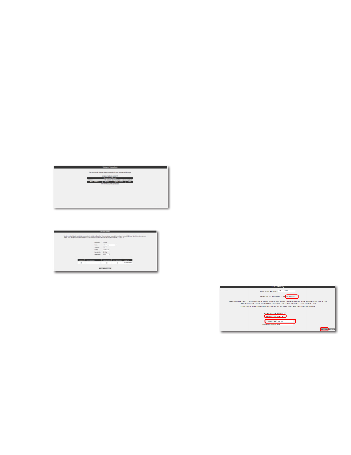
To enable WPA2 encryption and configure the necessary settings:
1. Go to “Wireless Security Settings” under the “WIRELESS” menu of the Web
interface of your router.
2. Click on the “WPA/WPA2” button in the “Security Type” section of the “Wire-
less Security” screen.
3. Select “Personal” as “Authentication Type”.
4. In the “Encryption Type” field you can choose between “WPA2” and “Both”. If
all the wireless devices on your network support WPA2, then select “WPA2”.
If some of the wireless clients support WPA only, then select “Both” in which
case the devices that support WPA2 will use WPA2 and those that do not
support it will use WPA over their wireless connection.
5. Enter a network key that is 8 to 63 characters long (use a combination of
letters and digits) in the “Passphrase” field. Make sure you choose a key that
is not easy to guess. Click “Save”.
6. You must enter the same passphrase for all the wireless clients that will
communicate with your device.
4.3.1 WPA2 Security
Settings

9
4.3.2 WPA Security
Settings
WPA (Wi-Fi Protected Access) encryption standard is one of the current wireless
encryption standards that provide a high level of data protection. All AirTies
wireless products and 802.11g compliant wireless communication devices
support WPA. If you would like to use WPA on your wireless network, all the
wireless adapters on your network must support WPA.
To enable WPA encryption and configure the necessary settings:
1. Go to “Wireless Security Settings” under the “WIRELESS” menu of the Web
interface of your router.
2. Click on the “WPA/WPA2” button in the “Security Type” section of the “Wireless
Security” screen.
3. Select “Personal” as “Authentication Type”.
4. In the “Encryption Type” field you have two choices: “WPA2” and “Both”. To
be able to use WPA encryption, select “Both” in which case the devices that
support WPA2 will use WPA2 and those that do not support it will use WPA over
their wireless connection.
5. Enter a network key that is 8 to 63 characters long (use a combination of letters
and digits) in the “Passphrase” field. Make sure you choose a key that is not
easy to guess. Click “Save”.
6. You must enter the same passphrase for all the wireless clients that will commu-
nicate with your device.
Your AirTies router supports WEP encryption in addition to the WPA and WPA2
encryption standards. If any of the devices in your wireless network does not
support WPA or WPA2, it is recommended that you choose WEP encryption.
To enable WEP encryption and configure the necessary settings:
1. Go to “Wireless Security Settings” under the “WIRELESS” menu of the Web
interface of your router.
2. Click on the “WEP” button in the “Security Type” section of the “Wireless
Security” screen.
3. Select “Open” for “Authentication Mode”.
4. In the “WEP Security Type” field, there are four choices for specifying a
network key.
1. 10 hexadecimal characters(A-F and 0-9) for 64-bit encryption
2. 5 ASCII characters for 64-bit encryption
3. 26 hexadecimal characters(A-F and 0-9) for 128-bit encryption
4. 13 ASCII characters for 128-bit encryption
You can enter up to 4 network keys and also choose the one you want to use.
Click “Save”.
5. You must enter the same password for all the wireless clients that will commu-
nicate with your device.
4.3.3 WEP Security
Settings

10
You can specify those clients that will be allowed access to your network using
MAC Filtering. MAC Filtering is not required for wireless security, but it is
recommended that you use it in addition to encryption for your data protection.
To enable MAC Address filtering and make the necessary settings for blocking
clients:
1. Click on “MAC Filtering” under the “WIRELESS” menu of the Web interface of
your router.
2. In the window that appears, check the “Enable MAC Filtering” box.
3. Select “Just Deny MAC Addresses in MAC List”.
4. For each device to be denied access, enter the wireless MAC address of the
device in the “New MAC Address” field or select from “Existing LAN Clients”
and then click the “ADD” button.
5. When you are done entering the MAC addresses, click “Save”.
6. To add the devices that will be allowed access to the wireless network, select
“Just Allow MAC Addresses in MAC List” instead of “Just Deny MAC Addres-
ses in MAC List” and enter the MAC addresses.
4.4 MAC Filtering AirTies Mesh Technology® resolves the signal loss and limited coverage area
problems often encountered in multi-story concrete buildings. To extend wireless
coverage area, one or more AirTies wireless access point devices functioning in
repeater mode are connected to your device to set up a “Mesh Network”. The
wireless access points communicate with each other via the Mesh protocol and
boost the signal wherever signal strength is low thus increasing wireless range.
Computers connect to the access point with the strongest signal and get to the
router over the Mesh Network. Thus, the weak signal or dead spots due to barriers
such as concrete walls are eliminated and the coverage area can be expanded to
the maximum.
To setup a Mesh Network with your device:
4.5 AirTies Mesh
settings

11
2. Go to “MESH” under the “WIRELESS” menu of the Web interface of your router.
In the “Mesh Settings” screen that comes up, click the “Search AP” button.
3. When you click the “Search AP” button, the router will start searching for
wireless access points to connect to within its range and list the access points
detected.
4. Check the box for the access point(s) that you would like your router to setup a
Mesh connection with. Select only those access points that have a signal level of
“Average” or better. Click “Save” to complete the Mesh settings of your device.
5. The same Mesh settings should be made on all the AirTies access points
selected above. You can find detailed information about Mesh settings for each
type of access point device in their user manuals.
Important: All AirTies devices that form the Mesh Network should operate on the
same channel.
5 ADVANCED
SETTINGS
You can do the installation and basic connection settings (ADSL and Wireless) of
your router using the Easy Setup CD included with your product. The Easy Setup
CD helps you do the initial installation of your device quickly and easily. In addition
to the CD, your router has an easy to use Web interface you can directly connect to
and configure the basic and advanced settings. You do not need to be connected
to the Internet to use the Web interface of your router. It is suicient to have your
computer connected to the router. Follow the steps listed below to access the Web
interface:
1- Open your web browser (Internet Explorer, Mozilla Firefox, etc.).
2- In the Address bar, enter 192.168.2.1, the default IP address of your device. This
will launch the Web interface of your router.
1. Go to “Wireless Setup” under the “WIRELESS” menu of the Web interface of
your router. Select a channel for your “Mesh Network” to operate in (it is re-
commended that you use one of channels “1”, “6”, or “11”) from the ones listed
in the “Channel” field. You should select the same channel on all the wireless
access point devices that form the “Mesh Network”.

12
3- In the “LOGIN” screen that comes up you will be prompted for a password to
login. Your router does not have a default password. Initially, leave this field
blank and continue by clicking “OK”.
Note: How to set a password for logging into the Web interface is explained in the
“Password Settings” sub section under the “MANAGEMENT” section.
The “HOMEPAGE” is the first screen that comes up after logging in. On this screen
you can find information on the general settings and current operating status of
your device.
5.1 Homepage
Any device that you connect to your router, such as PCs, network printers, IP
cameras, etc., is a client. Any operation related to clients that will have a local
network connection to your router can be done through the “LAN” menu of the Web
interface and its submenus.
When you click on the “LAN” menu, the “LAN Client List” screen will come up. All
clients that are connected to your router and their connection details are shown on
this screen.
5.2 LAN
Every client that is connected to your router is given a local IP address. The module
that assigns these IP addresses is the DHCP (Dynamic Host Configuration Protocol
) module. For IP and DHCP configuration of your router, go to “IP and DHCP
Settings” under the “LAN” menu.
5.2.1 IP and DHCP
Settings
You can change the IP address and Netmask of your router in this section. The
default IP Address of your device is 192.168.2.1, and the default Netmask is
255.255.255.0. You can change these values based on the needs of your existing
network.
Local IP Settings

13
This section is for DHCP related settings. The settings you can change are the
following:
DHCP is enabled by default. In this section you can assign an address range from
which the router can assign local IP addresses to clients and the lease time. The
default IP address range for your router is 192.168.2.2 through 192.168.2.254.
Maximum lease time for an IP address is set as 3600 seconds, which means the
assigned IP address will be renewed every 3600 seconds.
Enable DHCP Server
DHCP Settings
DHCP relay makes it possible for a DHCP server on a dierent network to assign
local IP addresses to clients connected to the router. To do this, the address of the
device (modem, server, etc.) that runs the DHCP service needs to be known.
Important: If DHCP Relay is enabled, the DHCP server of your router is disabled
and does not assign IP addresses to clients
Enable DHCP Relay
Stops all DHCP activity on the device. When in this mode, clients connected to
the router need to be assigned an IP address manually or they have to get an IP
address from another DHCP server in order to communicate with the network.
In order for any changes made to the IP or DHCP settings to take eect, you need to
click “Save”.
Disable DHCP
You can see all the clients connected to your router and their connection details
by selecting “LAN Clients” under the “LAN” menu of your router’s Web interface.
Through this menu, you can also reserve an IP address for a client. When an IP
address is reserved for a client, it cannot be assigned to any other client. Whenever
the client connects to the router, it can get the IP address reserved for it.
You can see the IP addresses that are reserved in the “Static Addresses” table.
“Dynamic Addresses” table shows the IP addresses assigned but not reserved.
Click “Save” for the changes you have made in the “LAN Clients” page to take
eect.
5.2.2 LAN Clients

14
A firewall prevents unauthorized Internet users from accessing your local network
and computer.
AirTies Firewall has SPI (Stateful Packet Inspection) feature. SPI monitors the pro-
tocol and packet addresses being received to determine if the information should
be passed through the firewall to the connected computers. Internet addresses
that are a source of malicious attacks are permanently blocked from accessing your
network.
You can also limit or block the Internet access of any local user by defining advan-
ced rules for Internet access.
The following sections describe the submenus under the “FIREWALL” menu of the
Web interface.
5.3 FIREWALL
settings
You can allow or block Internet access of any computer on your local network using
the Access Control feature. These access restrictions can be based on IP address
as well as MAC address.
Click “New” to define a new access rule.
5.3.1 Access control
In the window that appears:
• Enter a name for the access rule you would like to define in the “RULE NAME”
field. Choose a name that is easy to remember.
• In the “LAN Interface” field, enter the LAN interface to which the rule will apply.
(Routers that support VLAN have more than one LAN interface.)
• Select the PVC to which the access rule will apply in the “WAN Interface” field.
• In the “Select Client” section, enter the IP or MAC addresses of the clients
whose access you would like to restrict with this rule and click “Add >”.
• In the “Select Applications” section, specify the applications you would like to
block access to by the clients you have defined in the “Select Clients” section
previously. You can select the application from the “Existing Applications” list
and click “Add >””.
• You can specify the times that the Access Rule will be in eect by checking the
“Schedule” box. If you define scheduling rules, then the access rule will be in
eect only during the times specified.
• To add a new application to the “Existing Applications” list, click “New”. In the
window that appears:
o Enter a name for the application you are going to define in the “Application
Name” field.
o Enter the LAN and WAN ports the application uses and click “Save”.
• Click “Save” when you are done.
• To activate the rule you have defined, check the “Enable Access Control” box and
click “Save”.

15
MAC Address Filtering allows you to restrict network access based on MAC addres-
ses. When this feature is activated, the clients whose MAC addresses are on the list
will have their access to the router blocked.
To restrict access based on MAC Address:
• Check the “Enable MAC Filtering” box.
• Enter a MAC address or choose from the list of existing clients and click “ Add”.
• Click “Save”.
You can block access of any computer in your local network to the websites you
specify. In this window, you can enter the URL or any keyword that is part of the URL
for websites you would like to block access to.
• To activate the URL filtering feature check the “Enable URL Filter” box.
• In the “SELECT CLIENT” section, specify the IP or MAC addresses of the clients
that the URL filtering rule will apply to, clicking the “Add” button after each entry.
• Enter the URL’s you would like to block access to in the “Keyword” list.
• Click “Save”.
5.3.2 MAC address
ltering
5.3.3 URL lters
5.3.4 Anti-DoS The Anti-DOS feature prevents “Denial of Service” attacks that aim to disable your
router by ooding it with connection requests. In this window, you can set the maxi-
mum number of connections that will be allowed from the Internet for a specified
time interval for each protocol.
The Anti-DoS feature is disabled by default. To enable Anti-DoS and configure the
necessary settings:
• Check the “Enable Anti-DoS” box.
• Enter the maximum number of connections that will be allowed over the LAN
and Internet.
• Click “Save”.

16
5.4 NAT Network Address Translation (NAT) is a way to map an entire network (or networks)
to a single IP address. NAT allows multiple clients in your local network to access
the Internet through a single global IP address (WAN IP) assigned to you by your
Internet service provider.
You can enable/disable NAT using the “NAT” menu of your router’s Web interface.
NAT is enabled by default.
“Port Forwarding” is used in order for a host outside your local network to access a
host on your local network.
To configure Port Forwarding on your router, go to “Port Forwarding” under the
“NAT” menu of the Web interface of your router.
On the screen that appears, you will see the list of currently defined port forwarding
rules. If no rules have been defined yet, then the list will be empty. To define a new
port forwarding rule, click “New”
On the top section of the page that comes up, fill out the fields related to the
forwarding rule and the client PC’s the rule will apply to.
Rule Name: Enter a name for the new rule you are defining.
SELECT CLIENT: This section is for specifying the clients that the port forwarding
rule will apply to. Enter the IP address of the client in the “New IP Address” field or
select the IP address from the “Existing LAN Clients” list and click “Add>”. You will
see the new IP address in the “Selected Client IP” field.
5.4.1 Port
Forwarding
On the lower half of the screen, you can enter the port forwarding rule parameters.
• In the “Application Name” field, enter the name of the application for the port
forwarding rule you are creating.
• In the “TCP Ports” fields, enter the WAN and LAN TCP port numbers. (WAN and
LAN port numbers are determined by the application designer and are usually
the same)
• In the “UDP Ports” fields, enter the WAN and LAN UDP port numbers. (WAN and
LAN port numbers are determined by the application designer and are usually
the same) Click “Add>”.
All the values you have entered for the application will show up in the table below.
If the application for which you’d like to setup port forwarding is already on the
application list to the left of the page, you can just select it and click “Add>”. The
port numbers will be filled in automatically.
Click “Save” after you’ve entered all the parameters.

17
5.5 Routing
After you click “Save”, the following “Port Forwarding” screen will come up. Here,
you will see the port forwarding rule you have defined. After checking that all the
values displayed are correct, check the “Enable Port Forwarding” box. Then, click
“Save”.
The DeMilitarized Zone (DMZ) feature opens up all the ports of a single local
network host for unrestricted access from the Internet.
On your router, DMZ is disabled by default. To enable DMZ, go to the “DMZ” sub-
menu under the “NAT” menu of your router’s Web interface. On the “DMZ Settings”
screen that comes up, check the “Enable DMZ” check box. Specify the local IP
address of the network host that you would like traic to be forwarded to in the “IP
Address” field either by typing it in or selecting from the list. Click “Save”. From now
on, all packets coming from the Internet to your router’s WAN IP (no matter which
port) will be directed to the local client with the IP address you have specified.”
5.4.2 DMZ
Routing defines the rules that determine how IP packets reach their destination
on the Internet. You can either define static routing where you specify the target
IP addresses, and how to get to them or use RIP dynamic routing protocol which
updates the routing rules automatically. To specify which routing to use and set the
necessary parameters, click on the “ROUTING” menu of your router’s Web interface.
To define a static routing rule, go to “Static Routing” under the “ROUTING” menu of
the Web interface. You now need to enter a destination IP and how to get to it.
• Destination IP: Enter the IP address of the destination
• Netmask: Enter the Netmask for the destination IP address
• Connection: Enter the interface that will be used for the data transfer. It should
be set to “lan” for local IP addresses and “wan” for remote IP addresses.
• Gateway: Enter the IP address of the host that can transfer the data to the
“Destination IP”. This can be a WAN IP or a LAN IP address depending on the
connection type.
• Metric: In this field, you can specify the number of hops (how many gateways
the data needs to go through) to get to the destination IP.
5.5.1 Static Routing
Dynamic Routing uses RIP protocol to determine and update the routing rules
automatically based on the local and remote networks connected. There are two
versions of the routing protocol: RIP v1 and RIP v2. RIP v2 allows for encryption
between two routers.
To configure Dynamic Routing go to “Dynamic Routing” under the “ROUTING”
menu of your router’s Web interface and enter the following information:
• Enable RIP: Click this check box to enable dynamic routing.
• Protocol: If you would like to use RIP v2 and also have RIP v1 supported for
backward compatibility, then select “RIP v1 compatible”.
• Enable password: Check this box if you have chosen RIP v2 as the protocol and
you would like to use encryption between routers.
• Password: Enter a password. The same password must be used in all the other
routers.
When you use Dynamic Routing, for each of the LAN and WAN interfaces you can
specify in which direction data can be sent. You can select “inward”, “outward” or
“Both Directions”.
5.5.2 Dynamic
Routing

18
Your router does not have a default password for login. To login to the Web user
interface leave the “password” field blank and click “OK”. You can define a pas-
sword for the Web interface or change the existing password from the “Password
Settings” menu.
When you are assigning a password to the Web interface for the first time, on the
“Password Settings” screen, leave the “Current Password” field blank and enter
the password you would like to use in the “New Password” and once more in the
“Confirm Password” field. Click “Save”. From now on, you will have to use this new
password to login to the Web interface.
5.6.1 Password
Settings
The “MANAGEMENT” menu of your router’s Web interface lets you configure local
and remote management settings
5.6 MANAGEMENT
If you want to change your existing password, enter the password you’re currently
using in the “Current Password” field and the new password in the “New Pas-
sword” and “Confirm Password” fields, and click “Save”.
5.6.2 Remote
Management
To enter the settings related to the remote management of your device, go to
“Remote Management” under the “MANAGEMENT” menu.
To enable remote management of your device, click the “Enable Remote
Management” check box.
If you check the “Any IP” box, your router can be managed remotely from any
computer.

19
After saving, the WAN IP address you have entered will appear in the “IP Access
List”. If you select this address from the list and click “Save”, remote management
will be activated for this address. If you want to remove an IP address from the
list, select the address from the list, click on the “Delete” checkbox and then click
“Save”.
You can also specify which services will be available to the remote management
computers on this page.
If “Any IP” is not checked, you have to add the WAN IP address of the computer
from which you would like to remotely manage your device to the “IP Access List”.
To do this, enter the WAN IP address in the “New IP Address” field and click the
“Add” box.
TR-069 is an application layer protocol for remote management of end-user
devices. With TR-069, all the settings that can be configured over a local area
connection can be done automatically via remote Automatic Configuration Servers
(ACS). There are a few simple settings to be configured to use TR-069 for automa-
tic configuration. For these settings, go to “TR-069 Settings” under the “MANAGE-
MENT” menu.
• Enable TR-069: Check this box to enable TR-069.
• URL: The ACS address the router will connect to (given to the user by the ACS
provider)
• User Name: The user name to be used by the router to connect to the ACS
server (assigned to the user by the ACS provider)
• Password: The password to be used by the router to connect to the ACS server
(assigned to the user by the ACS provider)
• Periodic Inform Interval: the time in seconds after which the router and the
ACS server will check their connection status. The default period is set to 86400
seconds for your router.
• Connection Request User Name: The user name that the ACS will use to
connect to the router.
• Connection Request Password: The password that the ACS will use to connect
to the router.
After entering all the values, click “Save”.
5.6.3 TR-069
Settings

20
5.7.1 DDNS Settings
5.7 DDNS
To configure the DDNS settings of your router, go to “DDNS Settings” under the
“DDNS” menu of the Web interface. On the “DDNS Settings” screen that comes up,
you can see the current DDNS account information. To enter a new DDNS account,
click “New”.
To use the Dynamic DNS feature, you need to setup an account with a DDNS
service provider. On the screen that comes up, select a DDNS service provider and
enter your account information (Hostname, Username,Password). Click “Save”
after you have filled in the necessary fields.
Dynamic DNS (DDNS), ensures that your hostname and IP address in the Internet
name servers are always current. It’s primarily used to associate a domain name with
a dynamic IP address which makes it possible to access a computer with a dynamic
IP address over the Internet. It also allows you to run a server on a computer with a
dynamic IP address.
Clicking “Save” will take you to the “DDNS Settings” screen again. Here you can see
the account information you have entered and account status, and if you have more
than one DDNS service entry, you can change the active account. You can also edit
or delete the DDNS accounts you have previously entered.
To enable DDNS, check the “Enable DDNS” box and click “Save”.
• “Restore Config” lets you restore a previously saved configuration onto your
router Click the “Browse” button to locate the config.bin file that was previously
saved, and then press the “Restore Config” button to restore your settings from
this file onto your router.
On this page, you can restart your router, reset it to factory defaults, backup your
router’s current configuration or restore from a previous backup. To get to the
“Tools” screen, select “TOOLS” from the main menu of the Web interface.
• The “Restart” button restarts your router remotely. During this operation, your
connection to the router will be lost. You can reconnect after the router comes
back up.
• The “Restore Factory Defaults” button allows you to reset your router back to
factory defaults remotely. This will clear all the current settings on your router.
• “Backup Config” lets you save the current settings of your router onto your
computer. When you click the “Backup Config” button, your router will create a
file called “config.bin” to be saved on your computer. You can restore this
configuration later using the “Restore Config” button.
5.8 Tools
Table of contents
Other AirTies Wireless Router manuals