Airuno Parsifal 90 Assembly Instructions

1
Parsifal 90 & 120 Downdraft Extractor
Installation & User Instructions
Please read these instructions carefully before installing and
operating this appliance

2
Contents
1. Introduction
3
2. Health and Safety
3-4
3. Installation
4-8
3.1 Assembly Instructions
4-5
3.2 Motor Options
6
3.3 Re-Circulating Options
6
3.3.1 Plinth Charcoal Filter Kit
6
3.4 Electrical Wiring
6-8
3.4.1 Electrical Wiring Diagram
7
3.4.2 Controls
8
4. Use & Maintenance
8-9
4.1 Cleaning the Metal Filters
8
4.2 Carbon Filters
8-9
4.2.1 Polyester Carbon Filters
9
4.2.2 Long Life Carbon Filters
9
4.3 Cleaning the Hood
8-9
5. Technical Data
9
6. Dimensions
10-11
6.1 Parsifal 90
10
6.2 Parsifal 120
11

3
1. Introduction
Dear Customer,
We wish to thank you for choosing this Air Uno cooker
hood. In order to get the best performance from your
appliance we recommend that you read this booklet
carefully before operating the appliance for the first
time.
Revisions to the publication
In order to improve the product, to keep this
publication up to date the manufacturer reserves the
right to make modification without any advance
notice. Any reproduction, even in part, of this manual
without the consent of the manufacturer is
prohibited.
Care of the manual and how to consult it
Take good care of this manual and keep it in a
place which can be easily and quickly reached.
If this manual should be lost or destroyed, or if it
is in poor condition, ask for a copy from your
retailer, providing product identification data.
Information which is essential or that requires
special attention is shown in bold text.
ATTENTION
This warning sign indicates that the
message to which it refers should be
carefully read and understood, because
failure to comply with what these notices
say can cause serious damage to the
extractor and put the user’s safety at risk.
INFORMATION
This symbol is used to highlight
information which is important for proper
extractor operation. Failure to comply with
these provisions will compromise use of
the boiler and its operation will not be
satisfactory.
MANUAL
Indicates that you should carefully read
this manual or the related instructions.
2. Health and Safety
Installation of the cooker hood, making
electrical connections, checking its operation
and maintenance are all tasks which should be
carried out by qualified and authorised
personnel.
Install the cooker hood in accordance with the
regulations in force in your local area, region and
country.
For the correct use of the appliance and to
prevent accidents, the instructions given in this
booklet must always be followed.
Before beginning any operation, the user, or
whoever is preparing to operate on the
appliance, must have read and understood the
entire contents of this instruction booklet.
All responsibility for improper use is taken
entirely by the user and as such relieves Air Uno
of any civil or criminal responsibility.
In view of the fact that it is an electrical appliance,
do not touch the appliance with wet hands.
Before carrying out any cleaning or maintenance
operation, make sure in advance that the
appliance is isolated from the mains electricity
supply.
Incorrect installation or faulty maintenance (not
conforming to the requirements set out in this
booklet) can cause harm to people, animals or
property. In such cases Air Uno is absolved from
any civil or criminal responsibility.
This product complies with EU Directive
EU2002/96/EC.
The crossed bin symbol on the appliance indicates
that the product, at the end of its life, must be
disposed of separately from domestic waste, either by
taking it to a separate waste disposal site for electric
and electronic appliances or by returning it to your
dealer when you buy another similar appliance. The
user is responsible for taking the appliance to a special
waste disposal site at the end of its life. If the disused
appliance is collected correctly as separate waste, it
can be recycled, treated and disposed of ecologically.
WARNINGS:
-When the downdraft is closed, do not put pots
or other containers on it.
-This appliance can be used by children aged from
8 years and above and persons with reduced
physical, sensory or mental capabilities, or lack of
experience and knowledge if they have been
given supervision or instruction concerning use of
the appliance in a safe way and understand the
hazards involved.
-Children shall not play with the appliance.
Cleaning and user maintenance shall not be
made by children without supervision.
-The downdraft is equipped with a security
system of micro-switches, this blocks the

4
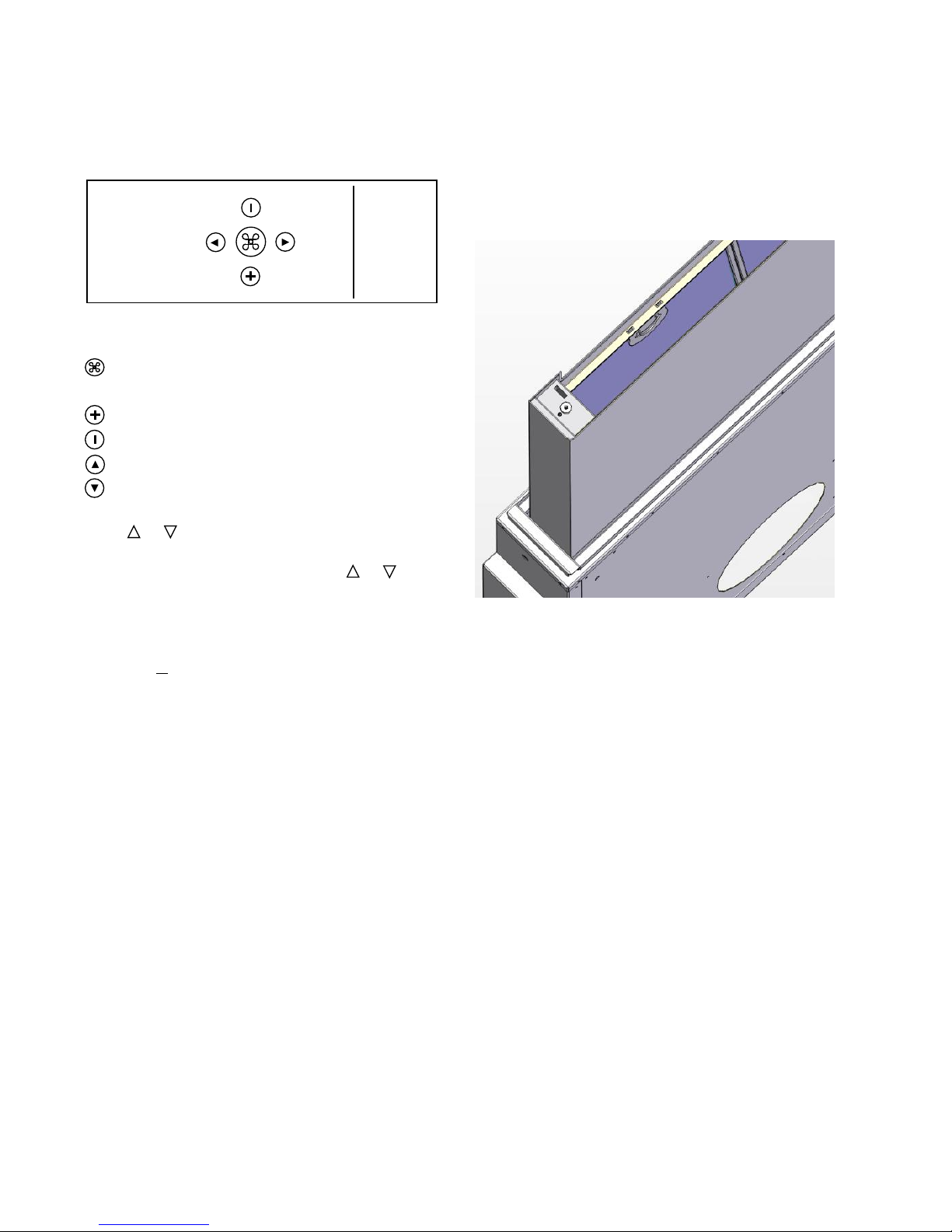
movement of the downdraft if the cover is
dislodged. When closing the downdraft, if an
object becomes trapped between the cover and
the worktop the dislodging of the cover will
immediately stop the downdraft. In order to
reactivate the downdraft the cover will need to
be replaced.
-Before cleaning or performing any periodic or
urgent maintenance to the hood, isolate the
mains supply and turn the main switch off.
-Do not connect the hood to any piping used for
combustion appliances, such as burners, boilers
or fire places.
-Check that the main power supply corresponds
to the voltage required by the hood, which is
given on the silver label stuck inside the hood.
Ensure that the electric system is correctly
earthed and that the earth discharge works
correctly.
-When cooking do not use any materials that
could form high or unusual flames. Oil that has
been used twice and fats are very dangerous
and could easily catch fire. Do not prepare
flambé dishes under the hood.
-Once the specialised technician has completed
the installation of the hood equipped with a
remote motor, all the leads, connectors, ground
connections and the remote motor must not be
accessible to the user. Only the installer is
granted access by removing screwed on panel.
-Respect local legislation and regulations issued
by the relative authorities regarding the exhaust
air when the suction is operating. Failure to
respect and perform all maintenance and
cleaning operations described in this handbook
could cause a fire hazard.
ATTENTION: Accessible parts may become hot when
the hood is used with cooking appliance.
3. Installation
The hood can be used for both filtering and suction.
When the filtering function is operating, i.e. with air
recycle, carbon filters must be used (refer to the
paragraph on Carbon filters page 11).
When the suction function is operating i.e. exhausting
the filtered air on the outside, a suitable
compensation system must be used according to
current standards in force. The diameter of the fume
exhaust pipe must be the same or greater than the
diameter of the hood pipe union.
There must be sufficient ventilation in the room
where the hood is installed, to allow simultaneous use
of other appliances that use gas or other fuels.
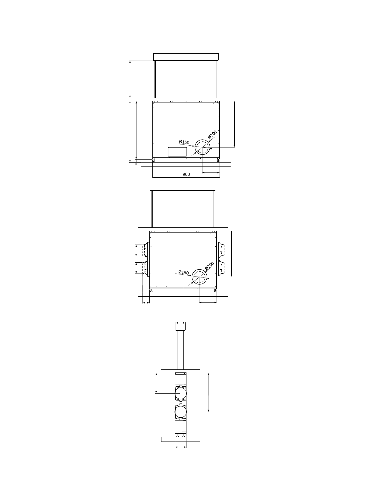
Ø150mm round or 220x90mm rectangular ducting
must be used. Ducting with a smaller diameter could
cause airflow issues.
3.1 Assembly Instructions
Attention: Before proceeding with the installation,
make sure that the screws and the anchors already
supplied, are suitable for the type of wall the hood
must be fixed to.
To assemble the hood use the accessories that are
supplied and follow the instructions given in the
enclosed hand book.
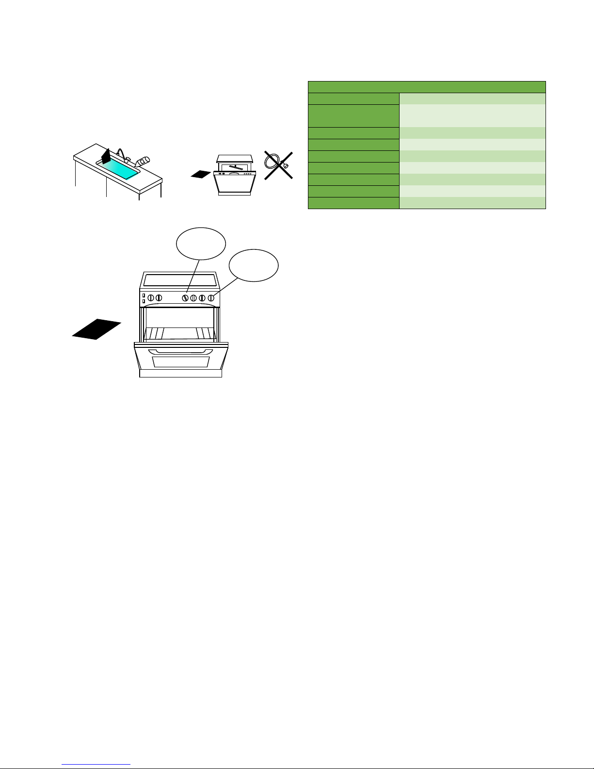
How the Parsifal should be laid out next to the hob
Fig 1
Parsifal 90 cut-out dimensions on top of worktop
Fig 2
Parsifal 120 cut-out dimensions on top of worktop
Fig 3
1. The Parsifal can be adjusted to suit a floor to
worktop height of between 820mm and 900mm.
Adjust the height of the leg support so the
Parsifal
120mm
To customer
requirements
Hob
50mm gap
900mm or 1200mm
873
123
1173
123

5
housing just fits under the kitchen top. Then use
the adjustable feet to raise the housing until it
touches the underside of the worktop (Fig 4).
Fig 4
2. Depending on the thickness of the worktop and
the cover, it is possible to achieve an adjustment
of 33mm. The difference in thickness between
the worktop and the cover must be at lease
17mm (Fig 5).
Fig 5
3. It is also possible to adjust the mechanism of the
Parsifal by tightening or un-tightening the two
nuts that secure the central pivot of the actuator
(Fig 6).
Fig 6
4. The gluing of the cover to the Parsifal must be
performed once it is in place. The space between
the lid and hole on the top should be about
1.5mm along the whole perimeter. The support
for gluing the cover is supplied with the Parsifal.
Caution: When the unit is positioned in the housing
always leave an access panel. This will be needed
should any technical assistance b required. An
authorised service engineer must carry this out.
Failure to comply with this condition will significantly
increase the costs that could be charged in the case of
any call outs.
5. Ducting will ideally be connected to the front or
back of the Parsifal. Remove the knock out panel
with a hammer and fix the 150mm diameter
plastic flange with the 4 screws included. Then
connect the ducting. (Fig 7 & 8).
Fig 7
Fig 8
It is also possible to connect ducting to the side of the
downdraft. Remove the knock out panel and fit the
metal tray and 150mm diameter plastic flange (Fig 9).
Fig 9
Housing
Parsifal
1.5
120 1.5
16
>17, <50
Knock out

6
3.2 Motor Options
The Parsifal can be used with any of the AMR09,
AMR10, AMR20, AME12, AMF10, AMF13 or AMD09
motors.
If you are using the AMD09 motor then this must be
attached directly to the side of the Parsifal this can be
at either side (Fig 10).
Fig 10
For the AMR09, AMR10, AMR20, AME12, AMF10 or
AMF13 motors you can duct from any of the 5 points
shown below (Fig 11).
Fig 11
3.3 Re-circulating Options
The Parsifal can be made re-circulating by using the
Plinth charcoal filter kit.
3.3.1 Plinth Charcoal Filter Kit
This option can only be used with the AMF10 or AMF13
motor. It is installed into the plinth attached to the
motor (Fig 12)
Fig 12
3.4 Electrical Wiring
The electrical wiring must be performed by a
specialised electrician fully respecting current
standards and legislation in force. Check that the
power supply corresponds to the voltage requested
by the hood, which is given on the silver label stuck
inside the hood. Ensure that the wiring system
conforms to current standards and the earth
discharge works efficiently. Pay special attention to
the hood power cable, ensure that it does not pass
through any holes without a cable clamp. For direct
connection to the electrical mains it is necessary to
provide a device that ensures disconnection from the
electrical mains, with an opening distance of the
contacts allows the complete disconnection under the
conditions of overvoltage category III, in accordance
with the rules of installation. The plug or Omni polar
switch must be accessible when the unit is installed.
If the power cord is damaged, it must be replaced by
a special cord or assembly available from the
manufacturer or its service agent. The cable must be
of type H05VV-F 3 x 0.75mm2minimum cross-section.
The manufacturer declines all responsibility if the
current accident prevention standards in force are
not respected, which are needed for the wiring
system to operate correctly.
The label with the technical information is placed on
the lid of the control box.

7
3.4.1 Electrical Wiring Diagram
1) Motor connection
2) 230V power supply
3) Cable with faston for microswitch
4) Remote antenna (must remain free)
5) Optional flat control cable
4
3
3
2
1
2
1
5
3

8
3.4.2 Controls
The Parsifal can be controlled by either the remote
control (Fig 10) or the optional ultra-flat membrane
control (Fig 11).
Fig 10
With the Parsifal completely extended it turns the
motor on at speed 2 and for turning the motor
off.
Increases motor speed.
Decreases motor speed.
Brings the Parsifal up.
Brings the Parsifal down.
If the or buttons are pressed while the Parsifal is
moving, the Parsifal automatically stops. To restart the
movement, it is necessary to push the or .
After 100 working hours of the motor, the red LED will
start to flash indicating the need to wash the metal
filters. To cancel the filters alarm, when the motor is off
press the button.
On first use the user will need to pair the remote
control with the Parsifal. With the hood turned off,
press and hold the button on the control box until the
LED flashes. Once this has happened press any button
on the remote control to check all functions are
working correctly.
To pair the ultra-flat membrane control press the plus
button until the LED flashes and then press any button
on the control to check all functions are working
correctly.
4. Use & Maintenance
Before beginning any sort of cleaning or
maintenance work, turn the power off to the hood
by turning the main switch to 0 (OFF).
4.1 Cleaning the Metal Filters
The metal filters fitted in the hood should be washed
every 2-3 months, depending on how much the hood
is used, using hot water and a liquid detergent that is
not too aggressive.
To access the metal filters, you must remove the cover
by lifting it off the two securing magnets. The metal
filters can be removed by using the special handle.
Unhook the handle then pull upwards (Fig 12).
Fig 12
4.2 Carbon Filters
The hood can be used with active carbon filters which
traps the cooking smells. There are either polyester or
long life carbon filters and these are situated behind
the grease filters.
4.2.1 Polyester Carbon Filters
These cannot be reused or washed and must be
periodically changed (every 4 months if the hood is
used for 2 hours every day). Saturated filters could be
a fire hazard. The filters in the Parsifal are rectangular.
4.2.2 Long Life Carbon Filters
These can be cleaned and reactivated. The filter
should be cleaned every other month if used
normally. The filter is best cleaned in a dishwasher at
the highest temperature using normal washing

9
detergent. The filter should be washed on its own to
prevent particles of food from fastening in it and then
causing an unpleasant smell later on (Fig 13). To
reactivate, the carbon filter should be dried in the
oven. Choose upper/lower heat and maximum 100°C
and dry the filter for 10 minutes (Fig 14). The filter
must be changed when it no longer absorbs the
cooking smells sufficiently.
OR
Fig 13
Fig 14
4.3 Cleaning the Hood
The surfaces of the hood should be cleaned
frequently, to avoid the risk of having to remove built
up and encrusted deposits and stains.
For the painted or copper plated hoods just a soft
cloth with warm water and a neutral detergent. Do
not pour the detergent directly onto the hood or use
powdery or abrasive products. For the stainless steel
hood, use special products and cloths for satin finish
stainless steel (not abrasive, corrosive detergents or
detergents containing chloride), ensuring to clean in
the same direction as the satin finish.
Do not use aggressive products, chemical solvents or
derivatives of oil distillates that could leave oily traces
which could cause oxidation and polymerisation.
The manufacturer accepts no responsibility for
damage to the surface of the hood due to failure to
respect these instructions.
5. Technical Data
Parsifal 900mm & 1200mm with AMF13 Motor
Control
Remote control/Flat membrane
Colour/finish
Black Glass/Stainless Steel/White
Glass
Airflow (m3/h)
855
Pressure (Pa)
760
Noise (db)
64-80
Power (W)
190
Voltage (V)
220-240
Outlet Width (mm)
150
Energy Class
B
65°C
100°C
10 min

10
6. Dimensions
6.1 Parsifal 90
X = adjustable between 40mm and 120mm
870
900
230
620
780
780 + X
X
500
96
230
620
Ø150
Ø150
120
140
263
502

11
6.2 Parsifal 120
X = adjustable between 40mm and 120mm
1170
1200
230
620
780
780 + X
X
500
96
230
620
Ø150
Ø150
120
140
263
502

12
CD (UK) Ltd T/A Air Uno
Unit L, Wakefield House
Thistle Way
Gildersome Spur
Morley
West Yorkshire
LS27 7JZ
CD (UK) Ltd T/A Air Uno is a company registered in England and Wales Registration No. 2905619
C
op
yri
g
ht
of
all
contents
of this
l
e
af
l
e
t
i
s
vested
i
n
CD (UK) Ltd t/a Air Uno.
Any
part
m
a
y
not be reproduced
w
i
t
hou
t
p
e
rm
i
s
si
o
n.
The
contents
of this
l
ea
f
l
e
t
are accurate at the date of
p
ri
n
t
i
ng
but, because
CD (UK) Ltd t/a Air Uno
has a
po
l
i
c
y
of
c
on
t
i
nual
d
e
ve
l
opm
e
n
t
,
i
t
may be
superseded
and
s
hou
l
d
be
d
i
sre
g
ard
e
d
if
sp
e
c
i
f
i
c
at
i
o
ns
or
appearances
are
c
ha
ng
e
d
.
The
statutory
rights of the customer are not affected.
E&O
E’
s.
This manual suits for next models
3
Table of contents
Other Airuno Ventilation Hood manuals

Airuno
Airuno Aida 90 Assembly Instructions

Airuno
Airuno Diamond 60 Assembly Instructions

Airuno
Airuno Chopin Evo Assembly Instructions

Airuno
Airuno Raffaello 120 Assembly Instructions

Airuno
Airuno Murano Evo Assembly Instructions

Airuno
Airuno Amadeus Assembly Instructions

Airuno
Airuno Salieri 90 Assembly Instructions

Airuno
Airuno Combiflow 800 Assembly Instructions
Popular Ventilation Hood manuals by other brands

KOBE
KOBE IS2236SQB-1 Installation instructions and operation manual

Atag
Atag WH255P/W3.0 manual

FALMEC
FALMEC Flipper NRS FLIPP85NW Instruction booklet

Caple
Caple Zi900SS Instruction on mounting and use

Zanussi
Zanussi Professional Master 642145 Specifications

AEG
AEG 8360 D OPERATING AND INSTALLATION Manual