13
4
Connecting Wires To Terminal Strips
Wiring Guidelines
Neatness Mandatory: Installation of the CONVRTR-60 and the DCC decoder will be in tight spaces
with minimum clearances. Take extra care and extra time to keep wiring neat, with wires trimmed to
the proper length and clear of mounting holes.
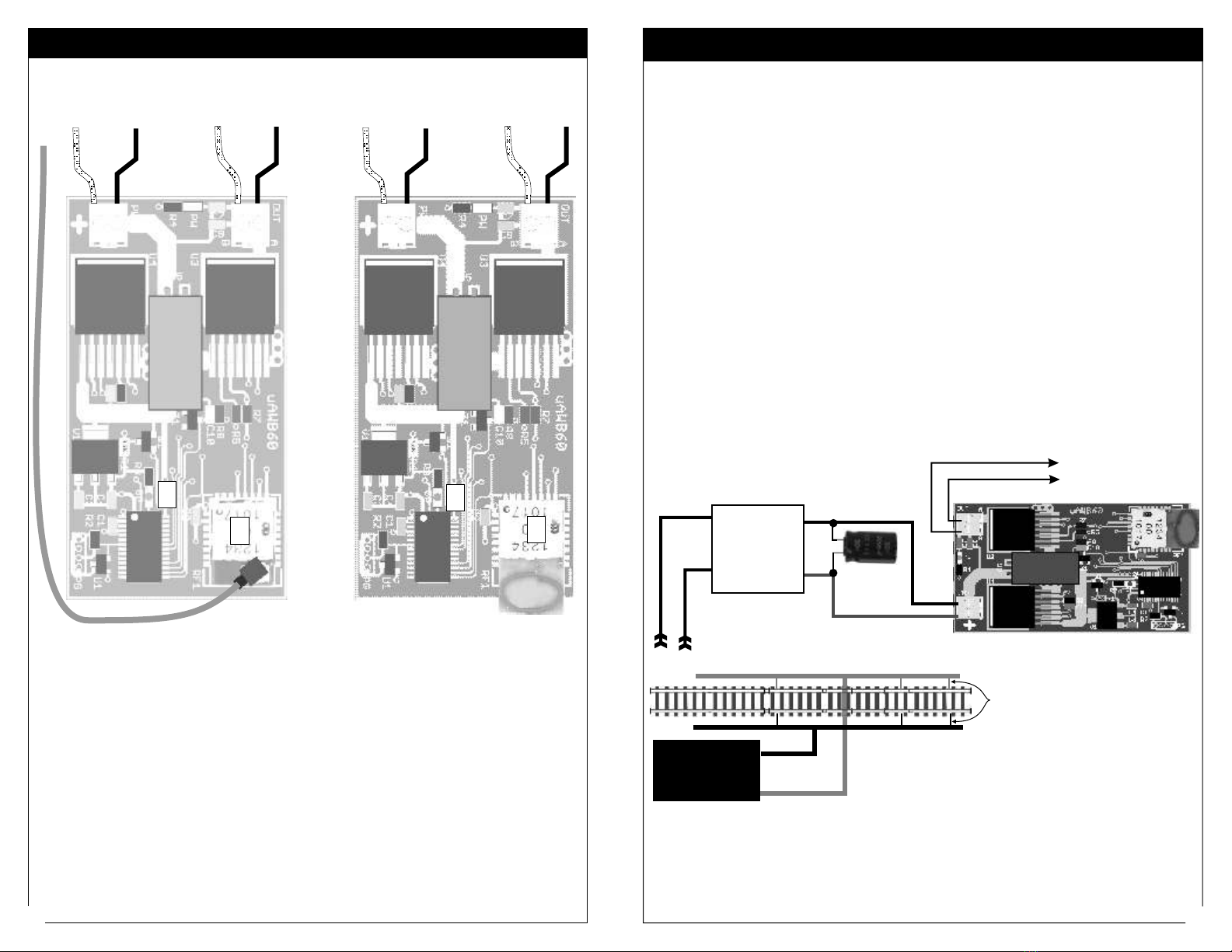
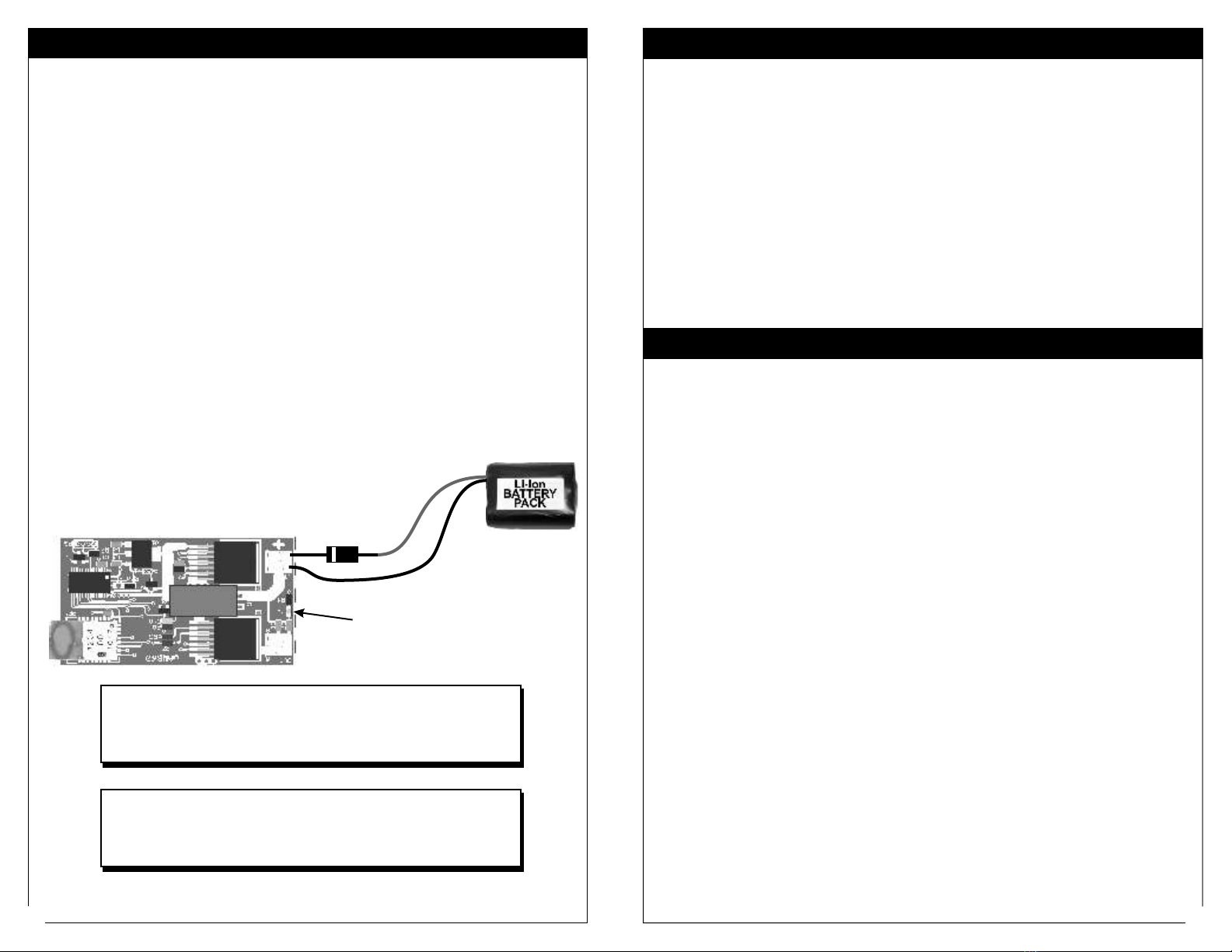
Basic CONVRTR-60 Connections: This is easy. There is a input terminal block for the battery
connection. The input is polarity sensitive. There is an output terminal block for connecting the DCC
decoder..
Verify Battery Polarity: There is no protection against polarity reversal. Connecting the
CONVRTR-60 to the wrong polarity will destroy it. Use the suggestions on the next page if you are
not sure of the polarity.
Battery Requirements: The CONVRTR-60 will operate with battery voltages as low as 8.2V and as
high as 22 volts. If using the higher voltages, you must first verify that the attached DCC decoder will
tolerate higher battery voltages.
Pick the highest energy capacity battery for which you have physical space. Energy capacity is stated
in milliamp-hour abbreviated mAhr or Amp-hours. This rating states how much current can be
supplied by the battery for 1 hour. A 500mAhr rating means the battery will supply 500mA or 0.5A for
one hour. A 3.4Ah rating means the battery will supply 3.4 Amps for one hour. Higher values offer
longer running time but the battery will be physically larger.
Make sure the battery fits the available space. There are many types and sizes available. Pick the
battery that offers the best compromise in space and energy capacity. For easiest installation of a
larger battery, use a separate battery car or a dummy locomotive.
See the battery suggestions and recommendations section at the end of this booklet.
DCC Decoder Types: Any NMRA-DCC compatible decoder may be connected to the CONVRTR-
60. For sound+motion, the TCS-WWOW or the Soundtrax Tsunami are recommended.
When connected to the CONVRTR-60, the DCC decoder will operate and can be programmed as if it
were sitting on the track and powered by a DCC system.
Wire: Small and flexible #20 - #24 AWG stranded wire is best although almost any kind of wire can
be used. Use multiple colors to prevent confusion or polarity reversal.
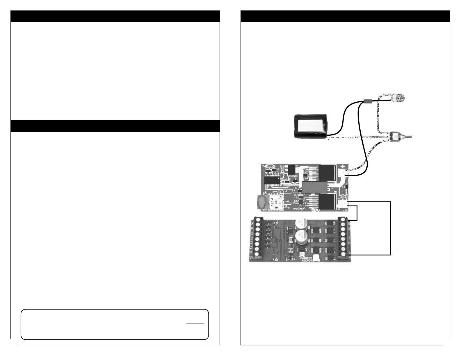
Power Switch and Charging Jack: A power switch is not absolutely necessary. You can equip the
battery with a simple plug and socket and that becomes the power switch. A latching reed relay can
substitute for a switch. See page 10 for details.
Troubleshooting Tips - continued
CONVRTR-60 Was Running But Suddenly Stops and Won’t Restart
1) Battery is depleted. Recharge the battery.
2) Jamming. Make sure that another throttle is not jamming your frequency and/or address.
3) Mechanical failure inside the locomotive.
4) Some kind of fault with the attached DCC decoder
CONVRTR-60 Won’t Run AtAll After Installation
1) Battery is depleted. Recharge the battery
2) Jamming. Make sure another throttle is not jamming your frequency or address.
3) Throttle not set to proper frequency or address. Set the throttle correctly or use the JUMPMODE to
program the CONVRTR-60 to the desired frequency. If you are not sure what the frequency is, follow
the instructions in the section labeled, ‘Forgotten Frequency.”
4) Some kind of wiring fault is continuously tripping the CONVRTR-60’s protection. The most
common cause is a pinched wire shorting to an adjacent wire or simply incorrect wiring. There may
also be a problem with the attached motion/sound decoder.
Beware of Lurking Locomotives When Using SERVICE PROGRAM Mode
SERVICE PROGRAM mode is a broadcast command that can be heard and understood by any other
AIRWIRE decoder or CONVRTR-60 sharing the same frequency as the CONVRTR-60. If another
decoder receives the command, it too will be programmed. Play it safe and make sure to turn off
power to all locomotives not being programmed.
Beware of Other Transmitters
CONVRTR-60
CONVRTR-60
If possible, mount the CONVRTR-60 horizontally and as high as possible within the locomotive. If
you are using the CONVRTR-60X with a whip antenna, a vertical antenna may offer better range
although you should also try horizontal. Keep the whip antenna away from motor and battery wiring
as much as possible. Never let it touch anything metal. For metal locomotives, the use of the external
antenna is mandatory. Make sure the antenna is as far outside of the metal chassis as possible.
The CONVRTR-60 decoder operates in an unlicenced band shared by many other transmitters. These
transmitters can create interference, cause intermittent throttle operation or failure of one or more of
your decoder’s 17 frequencies. The sources of these external interfering signals can be from your
own home or from adjacent homes and businesses. They can also be from other CVP wireless
equipment.
Here's a list of devices known to have caused interference problems to AirWire900 equipment:
wireless devices attached to computers, TV/Radio/Entertainment-center, remote controls, cordless
telephones, alarm systems, baby monitors, unlicenced personal communication devices, lawn
sprinkler controllers, remote starter switches, cordless light switches, outdoor lighting controllers,
toys, wireless headphones, and games. Of course, if you have additional wireless throttles, make sure
each is on its own frequency; two throttles on the same frequency will jam each other.
If you find a strong interfering signal on one or more of your frequencies, don’t use those frequencies.
You must select another, different frequency.
Never Use RTV or SiliconAdhesive On The CONVRTR-60
NEVER use RTV or other liquid adhesive to attach the to the locomotive. That
material is conductive and will destroy the . Use only double-sided foam tape.
Placement Suggestion For Best Range - Metal Locomotives
Operational Considerations
Not Sure About The CONVRTR-60’s Frequency?
Not sure about the ’s frequency? Don’t worry. Use the forgotten frequency
procedure to set it to what you need. It’s fast and painless as described on page 10.
CONVRTR-60
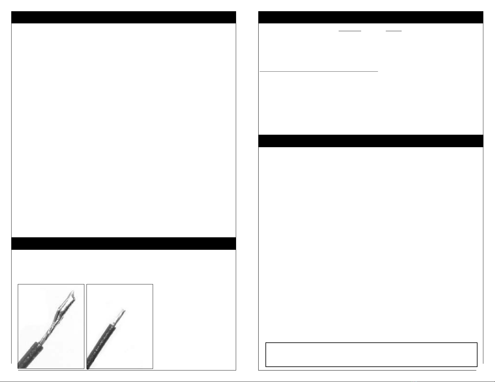
Wrong Right
If using stranded wire, it should always be tinned.
Remove about ½ of an inch of insulation from the wire. Tightly twist the individual strands together.
Use a soldering iron and heat the wire. Then apply a small amount of solder to the wire strands. This
process, called tinning, keeps stray wires from shorting across to the adjacent terminal or to other
areas of the board. Trim the tinned wire to about 1/4 inch.
When inserted into the terminal,
only a tiny part of the bare wire
will be visible.
Notice that the wire has been
trimmed in the “right” image.
Always use different wire colors.
The terminals will accept wire as
large as 20-22 AWG. However,
the twisting and tinning may
thicken an already large wire to
the point where it doesn’t fit.