AIT ASGC 34.5TL-4P4W Guide

ASGC 34.5TL-4P4W
User Installation Manual
www.ait.ac.at

2
About this Manual
Purpose
The purpose of this User Installation Manual is to provide explanations and
procedures for installation and operation for the AIT Smart Grid Converter.
Scope
The Manual provides safety information and guidelines, setup information,
procedures for installing the AIT Smart Grid Converter, as well as information
about operating the converter.
Organization
This manual is organized into the following chapters.
Chapter 1, “Introduction” provides information about AIT Smart Grid Converter.
Chapter 2, “Installation and Configuration” provides information and procedures
for installing and configuring the converter.
Chapter 3, “Operation” contains information on the basic operation of the
converter.

3
Contents
1Introduction.........................................................................................4
1.1 Description of the AIT Smart Grid Converter.......................................4
1.2 Key features...................................................................................4
1.3 Physical Features ............................................................................5
2Installation and Configuration.................................................................6
2.1 Package Inspection..........................................................................6
Scope of delivery..................................................................................6
Nameplate...........................................................................................6
2.2 Mounting ..........................................................................................6
Requirements for the mounting location ..................................................6
Permitted mounting positions.................................................................7
Recommended clearances......................................................................7
Mounting the converter .........................................................................7
2.3 DC Connection................................................................................8
Assembling DC connector ......................................................................8
Connecting the converter.......................................................................9
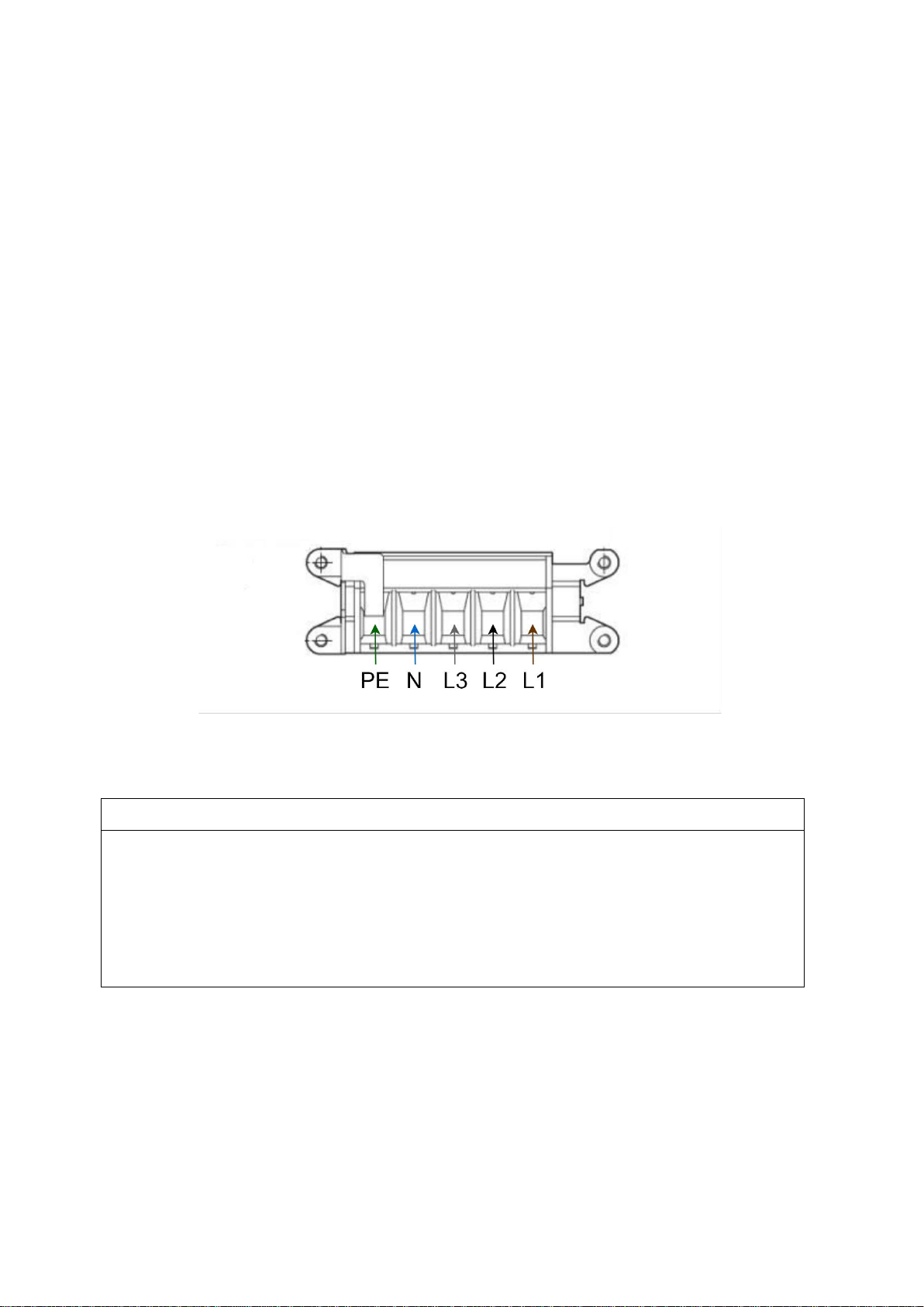
2.4 AC Connection ................................................................................9
Assembling AC plug ..............................................................................9
Connecting the converter..................................................................... 11
2.5 Communication Interface ............................................................... 11
3Operation .......................................................................................... 13
3.1 Setup .......................................................................................... 13
3.2 User Interface............................................................................... 14

4
1 Introduction
1.1 Description of the AIT Smart Grid Converter
AIT Smart Grid Converter is a four phase four wire converter designed for today‘s
Smart Grid and emerging Low Inertia Micro Grid applications. With seamless
transition between Grid Forming, Off-Grid and Grid Supporting modes, its highly
reliable cooling concept designed to ensure long life time, broad range of
connectivity options: IEC61850, ModBus TCP, SunSpec, and modular and
stackable concept of increased power handling capability, the AIT Smart Grid
Converter presents a perfect Smart Grid fit.
1.2 Key features
•Superb handling of arbitrarily unbalanced grid current, voltage and load
conditions
•Grid forming modes: Droop, Virtual Synchronous Machine with Virtual
Inertia
•Grid Support modes: PV, BESS, Battery simulator, Grid Currents balancer,
Active Front End, Back-2-Back,
•Off-grid
•Full four quadrant operation
•Active/Reactive power: full circular capability
•Immediate control: P, Q, PF
•Grid functions: Frequency-Watt/P(f), Volt-Var/Q(U), Volt-Watt/P(U)
•Anti-islanding
•Low/High Voltage ride through with Fast Reactive Current Response
•Grid code and safety standards compliance

5
1.3 Physical Features
Figure 1Location of physical features of the converter - side view
Figure 2Location of physical features of the converter - bottom view

6
2 Installation and Configuration
2.1 Package Inspection
Scope of delivery
Item
Quantity
Smart Grid Converter
1
AC plug
1
USB 2.0 cable
1
Nameplate
The nameplate is affixed to the converter and provides the following information:
•Model name
•DC input data
•AC output data
•Certification
2.2 Mounting
Requirements for the mounting location
•A solid support surface must be available for mounting.
•The mounting location must be suitable for the weight and dimensions of
the converter.
•The mounting location should be freely and safely accessible at all times.
•Climatic conditions must be met.

7
Permitted mounting positions
•The unit can be wall-mounted or put horizontally on a flat surface like a
desk or a workbench.
Recommended clearances
•Maintain the recommended clearances to walls as well as to other objects
to ensure adequate heat dissipation.
•Minimum 25 cm from the air openings on the bottom and on the side of
the converter.
Mounting the converter
CAUTION
Risk of injury when lifting the converter, or if it is dropped
The Smart Grid Converter weighs 45 kg. There is risk of injury if the converter
is lifted incorrectly or dropped while being transported or when attaching it to
or removing it from mounting surface.
•Transport and lift the converter carefully.
•The service person should be equipped with appropriate PPE.
•Lift the converter with the help of another person or a crane.
Tools:
•4 screws (M6 or M8)
•4 washers (M5), suitable for the screws
•Screwdriver and wrench (M5)
Procedure:
1. Select a wall or a suitable flat surface capable of supporting the weight of
the converter.
2. Maintain a minimum clearance of 25 cm from converter air openings to
surrounding objects.
3. Use two lifting handles on top of the converter to lift the converter and
adjust its position.

8
4. Using four M6/M8 screws, securely attach the converter mounting brackets
to the mounting surface.
5. Once the converter is securely tightened with screws to the wall, release it
from the lifting handles.
2.3 DC Connection
DANGER
Hazard of electric shock
•Test using a meter to make sure all the circuits are de-energized. Follow
a lock-out tag-out procedure.
Ensure that the following requirement is met for installation:
•All the components installed between the DC Source and the converter
shall be rated for at least 1000 VDC and as per the applicable installation
codes.
Table 1PV input parameters
Parameter
ASGC 34.5TL-4P4W
Maximum input voltage
1000 VDC
Maximum input current
60 A
Maximum MPP voltage
950 V
Minimum MPP voltage
570 V
Assembling DC connector
Cable requirements:
•Cable type: stranded, copper wire
•Cross section: 10 mm2 to 16 mm2
•Nominal voltage: UL/SCA/ICE 1000 V
•M5 16mm2or M6 16mm2cable lugs (e.g. Klauke 3R5)

9
Procedure:
•Strip cable insulation (e.g. 13mm for Klauke 3R5)
•Insert the stripped cable into the cable lug.
•Press the cable lug down with a crimping tool.
Connecting the converter
1. Ensure that the constant DC voltage source or the PV Array simulator have
sufficient rating.
2. Use a bi-directional DC source for the battery mode applications.
3. Connect the assembled DC cables according to the pin assignment shown
in Figure 2.
4. Tighten the screws on the DC terminal block with 2.5 Nm to 3 Nm torque
in order to secure the DC cables.
2.4 AC Connection
The converter can be connected either to a grid simulator or directly to the grid.
An AC breaker is to be used to protect the grid side of the converter. Use a three
phase, four pole MCCB breaker rated at 63 A (e.g. Lovato Miniature Circuit
Breaker 4P, 63 A, 10 kA, Curve B).
Assembling AC plug
AC cable between the converter and the breaker should be no longer than 2 m.
Cable requirements:
•Cable type: jacketed with five insulated conductors (e.g. Lapp Ölflex
Classic 110 5 G 10 mm2) or suitable substitute
•Cross section per conductor: 10 mm2
•5 x 10 mm2 ferrules
•Phoenix Contact contact insert Mnf Part Number: 1607474
•Pheonix Contact sleeve housing Mnf Part Number: 1855120

10
Procedure:
1. Remove the sleeve from the AC cable by 200 mm.
2. Strip the insulation of L1, L2. L3, N and the grounding conductor (PE) by
14 mm.
3. Conductors L, N and the grounding conductor (PE) should each be fitted
with appropriate size ferrules.
4. Insert the conductors according to Figure 2 and tighten the screws with
1.5 Nm ±0.3 Nm torque.
5. Place the contact insert into the sleeve housing.
6. Tighten the four screws on the front side of the contact insert with 1.5 Nm
±0.3 Nm torque.
7. Secure the sleeve housing with a cable gland.
Figure 3AC conductors connection
NOTICE
Risk of equipment damage
•Ensure that L1, L2, L3, N and PE connections are done correctly.
•AC plug openings are labelled 1, 2, 3, 4 and ground, however L1
conductor must be inserted into opening 4, L2 conductor into opening 3
and L3 conductor into opening 2, N into opening 1.

11
a) b)
Figure 4Assembled AC plug a) side view b) front view
Connecting the converter
1. Ensure that there is a circuit breaker connected between the AC source
and the converter.
2. Insert the assembled AC plug into the converter AC terminal shown in
Figure 2.
3. Tighten mounting screws of the AC plug with 1.5 Nm ±0.3 Nm torque.
2.5 Communication Interface
The communication interface resides on Safety Extra Low Voltage (SELV)
potential.
The communication interface is shown in Figure 5.
Figure 5Communication interface
SGC Power Sharing and Stacking Port
SFP+1 – Small Form-factor Pluggable Plus Transceiver 1
SFP+2 – Small Form-factor Pluggable Plus Transceiver 2

12
ModBus/SunSpec and TCP/IP Server Port
Ethernet Port
SGC GUI Port
SCI – Serial Communications Interface
DIOs connector – Digital Inputs and Outputs
DIO.1
Digital Input 1
DIO.2
Signal Ground
DIO.3
Digital Input 2
DIO.4
Signal Ground
DIO.5
Digital Input 3
DIO.6
Signal Ground
DIO.7
Digital Input 4
DIO.8
Signal Ground
DIO.9
Digital Output 1 Open Collector
DIO.10
Digital Output 1 Common
DIO.11
Signal Ground
DIO.12
Digital Output 2 Open Collector
DIO.13
Digital Output 2 Common
DIO.14
Signal Ground
DIO.15
Digital Output 3 Open Collector
DIO.16
Digital Output 3 Common
DIO.17
Signal Ground
DIO.18
Digital Output 4 Open Collector
DIO.19
Digital Output 4 Common
DIO.20
Signal Ground
CAN connector – Controller Area Network
CAN.1
HIGH level CAN bus line
CAN.2
HIGH level CAN bus line
CAN.3
LOW level CAN bus line
CAN.4
LOW level CAN bus line

14
3.2 User Interface
3. Download Typhoon HIL Control Center from the link. Sign up if you don’t
have an account. For more information on how to use Typhoon HIL Control
Center refer to Typhoon HIL Documentation.
4. In Windows Search look for Standalone HIL SCADA which is provided as a
part of Typhoon HIL Control Center.
5. Load the latest SGC GUI. Figure 7 shows a typical SGC GUI (appearance of
the latest SGC GUI might be somewhat different) .
Figure 7SGC GUI
Table of contents