Aiwa XR-M70 User manual

(For assistance and information,
call toll free I-800-BUY-AIWA.
I(United States and Puerto Rico)
B8-CLB-913-01
98041 0AYK-H-6 ai3i?3
DIGITAL AUDID

WARNING
TO REDUCE THE RISK OF FIRE OR ELECTRIC
SHOCK, DO NOT EXPOSE THIS APPLIANCE TO
RAIN OR MOISTURE.
A@
RISK OF ELECTRIC SHOCK
DO NOT OPEN
~A●
“CAUTION TO REDUCE THE RISK OF
ELECTRIC SHOCK,
DO NOT REMOVE COVER (OR BACK).
NO USER-SERVICEABLE PARTS INSIDE.
REFER SERVICING TO QUALIFIED
SERVICE PERSONNEL.”
Explanation of Graphical Symbols:
The lightning flash with arrowhead symbol,
A
within an equilateral triangle, is intended to
alert the user to the presence of uninsulated
“dangerous voltage” within the product’s en-
closure that may be of sufficient magnitude to
constitute arisk of electric shock to persons.
The exclamation point within an equilateral
A
triangle is intended to alert the user to the
presence of important operating and mainte-
nance (servicing) instructions in the literature
●accompanying the appliance.
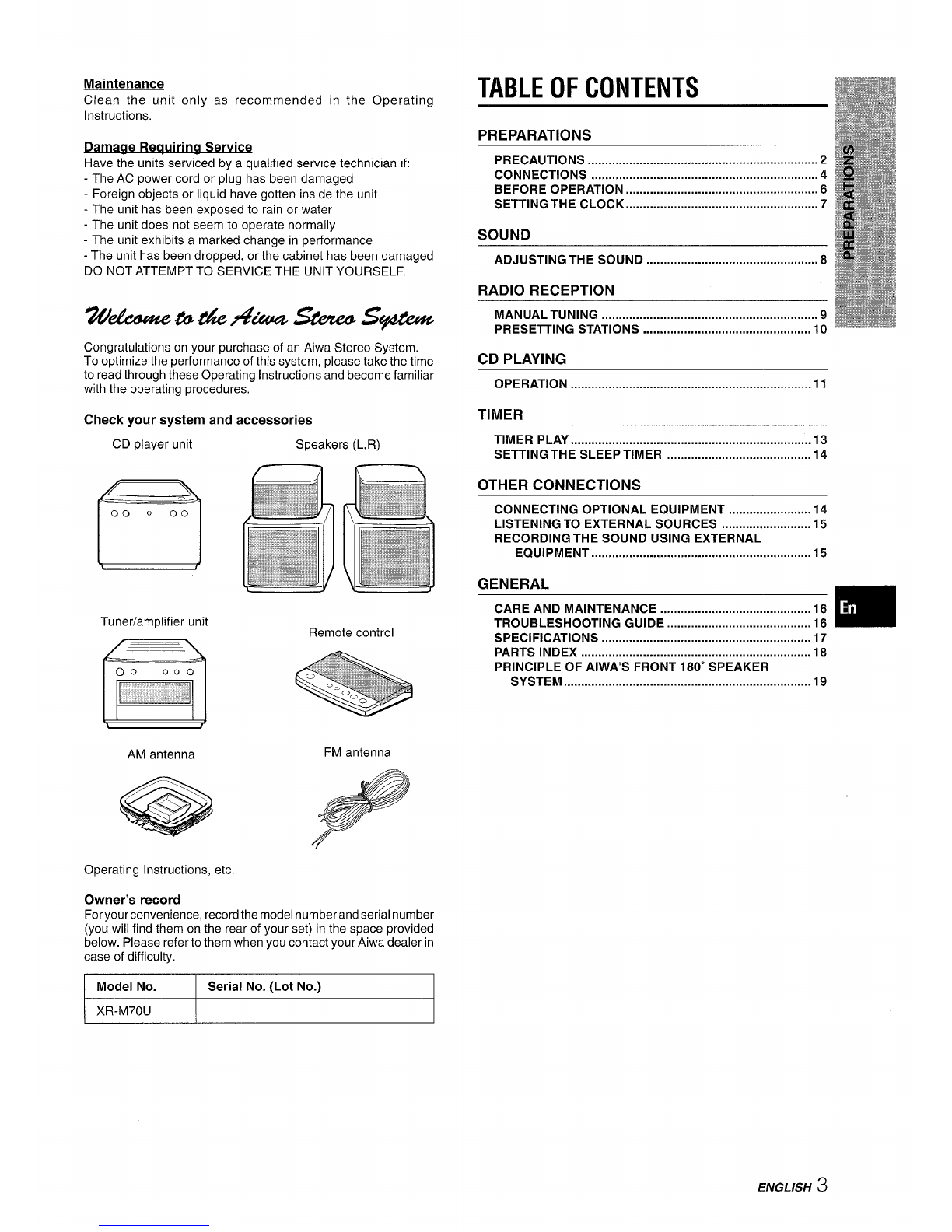
PRECAUTIONS
Read the Operating Instructions carefully and completely before
operating the unit. Be sure to keep the Operating Instructions for
future reference. All warnings and cautions in the Operating
Instructions and on the unit should be strictly followed, as well as
the safety suggestions below.
Installation
1
2
3
4
5
6
Water and moisture —Do not use this unit near water, such
as near abathtub, washbowl, swimming pool, or the like.
Heat —Do not use this unit near sources of heat, including
heating vents, stoves, or other appliances that generate heat.
[t also should not be placed in temperatures less than 5°C
(41 ‘F) or greater than 35°C (95”F).
Mounting surface —Place the unit on a flat, even surface.
Ventilation —The unit should be situated with adequate space
around itsothat proper heat ventilation is assured. Allow 10cm
(4 in.) clearance from the rear and the top of the unit, and 5 cm
(2 in.) from the each side.
-Do not place the unit on a bed, rug, orsimilarsurface that may
block the ventilation openings.
-Do not install the unit in abookcase, cabinet, or airtight rack
where ventilation may be impeded.
Objects and liquid entry —Take care that objects or liquids
do not get inside the unit through the ventilation openings.
Carts and stands —When placed or
mounted on a stand or cart, the unit should
be moved with care.
Quick stops, excessive force, and uneven
@
●L
surfaces may cause the unit or cart to 3
overturn or fall. A&*
7Condensation —Moisture may form on the CD pickup lens
when:
-The unit is moved from acold spot to awarm spot
-The heating system has just been turned on
-The unit is used in avery humid room
-The unit is cooled by an air conditioner
When this unit has condensation inside, it may not function
normally. Should this occur, leave the unit for afew hours, then
try to operate again.
8Wall or ceiling mounting —The unit should not be mounted
on a wall or ceiling, unless specified in the Operating instruc-
tions.
Electric Power
1
2
3
4
5
Power sources —Connect this unit only to power sources
specified in the Operating Instructions, and as marked on the
unit.
Polarization —As asafety feature, some units are equipped
with polarized AC power plugs which can only be inserted one
way into apower outlet. If it is difficult orimpossibleto insert the
AC power plug into an outlet, turn the plug over and try again,
If it still does not easily insert into the outlet, please call a
qualified service technician to service or replace the outlet. To
avoid defeating the safety feature of the polarized plug, do not
force it into apower outlet.
AC power cord
-When disconnecting the power cord, pull out by the plug. Do
not pull the cord itself.
-Never handle the power plug with wet hands, as this could
result in fire or shock.
-Power cord should be routed to avoid being severely bent,
pinched] or walked upon. Pay particular attention to the cord
from the unit to the power socket.
-Avoid overloading AC power plugs and extension cords
beyond their capacity, as this could result in fire or shock.
Extension cord —To help prevent electric shock, do not use
apolarized AC power plug with an extension cord, receptacle,
or other outlet unless the polarized plug can be completely
inserted to prevent exposure of the blades of the plug.
When not in use— Disconnect the AC Dower cord from the AC
outlet if the unit will not be used for several months or more.
When the cord is plugged in, asmall amount of current
continues to flow to the unit, even when the power is turned off.
Outdoor Antenna
1
2
Power lines —When connecting an outdoor antenna, make
sure it is located away from power hnes.
Outdoor antenna grounding —Be sure the antenna svstem
is properly grounde~ to provi~e protection against unexpected
voltage surges or static electricity build-up. Article 810 of the
National Electrical Code, ANS1/NFPA 70, provides information
on proper grounding of the mast, supporting structure, and the
lead-in wire to the antenna discharge unit, as well as the size
of the grounding unit, connection to grounding terminals, and
requirements for grounding terminals.
Antenna Grounding According to the National Electrical Code
)
(NEC ART 250 PART H)
NEC-NATIONAL ELECTRICAL CODE
2ENGLISH

]Vlaintenance
Clean the unitonly as recommended in the Operating
Instructions.
lDamage Requiring Service
I+ave the units serviced by aqualified service technician if:
The AC power cord or plug has been damaged
-Foreign objects or liquid have gotten inside the unit
-The unit has been exposed to rain or water
.The unit does not seem to operate normally
-The unit exhibits amarked change in performance
-The unit has been dropped, or the cabinet has been damaged
IDO NOT ATTEMPT TO SERVICE THE UNIT YOURSELF.
76k&u#wzb6&A%asbze@s#i?#lw
Congratulations on your purchase of an Aiwa Stereo System.
“ro optimize the performance of this system, please take the time
to read through these Operating Instructions and become familiar
with the operating procedures,
{Check your system and accessories
CD player unit Speakers (L,R)
Tuner/amplifier unit
AM antenna
Operating Instructions, etc.
Owner’s record
Foryourconvenience, record the model number and serial number
(you will find them on the rear of your set) in the space provided
below. Please refer to them when you contact your Aiwa dealer in
case of difficulty,
[Model No. Serial No. (Lot No.)
TABLE OF CONTENTS
PREPARATIONS
PRECAUTIONS ...................................................................2
CONNECTIONS ..................................................................4
BEFORE OPERATION ........................................................6
SETTING THE CLOCK ........................................................7
SOUND
ADJUSTING THE SOUND ..................................................8
RADIO RECEPTION
MANUAL TUNING ...............................................................9
PRESETTING STATIONS .................................................10
CD PLAYING
OPERATION ......................................................................11
TIMER
TIMER PLAY ...................................................................... 13
SETTING THE SLEEP TIIMER .......................................... 14
OTHER CONNECTIONS
CONNECTING OPTIONAL EQUIPMENT ........................ 14
LISTENING TO EXTERNAL SOURCES .......................... 15
RECORDING THE SOUND USING EXTERNAL
Equipment ................................................................l5
GENERAL
CARE AND MAINTENANCE .s..........................................16
TROUBLESHOOTING GUIDE .......................................... 16 m
SPECIFICATIONS .....................................m...m ..........m .......m 17
PARTS INDEX ................................................................... 18
PRINCIPLE OF AIWA’S FRONT 180” SPEAKER
sYsTEM .................m......................................................l9
IXR-M70U II
ENGLISH 3

CONNECTIONS
Before connecting the AC cord
The rated voltage of your system shown on the rear panel is 120
VAC. Check that the rated voltage matches your local voltage.
IMPORTANT
●Connect the speakers, antennas, and all optional equipment
first. Then connect the AC cord in the end.
●There are no differences between the front speakers. Both
speakers can be connected as L(Left) or R(Right).
7Place the CD player unit on top of the tuner/
amplifier unit and plug in the connector of the
flat cable as shown below.
Note that the connector can be plugged in in only one direction
with the flat cable facing right.
~c.pbferunit
After plugging in the connector, allow adequate clearance
between the flat cable and the ventilation openings.
2Connect the speaker cords to the tuner/amplifier
unit.
The speaker cord from the right speaker should be connected
to the “R” jack and the cord from the left speaker to the “L”
jack.
,lRtl’jack &To;ot:::ft
To the right
speaker
M
—
3Q3FM antenna
AM antenna ~
~1-111~
Left speaker
AC cord
4ENGLISH

Connect the supplied antennas,
Connect the FM an_tenna to the FM 75 Qterminals and the
AM antenna to the AM LOOP terminals.
AM FM antenna
4Connect the AC cord to an AC outlet.
When the AC cord is connected for the first time, the display
window demonstrates the functions of the system. When the
power is turned on, the demonstration display is overridden by
the operation display. When the power is turned off, the
demonstration mode is restored.
To cancel the demonstration
Press the DEMO button.
To activate, press the DEMO button again.
To stand the AM antenna on asurface
Fix the claw to the slot.
To position the antennas
FM feeder antenna:
Extend this antenna horizontally in aT-shape and fix its ends to
the wall.
AM loop antenna:
Position to find the best direction.
m
PLACING THE TWO UNITS SIDE BY SIDE
You may also place the CD player and the tuner/amplifier units
side by side according to your preference.
In this case, make sure that the flat cable does not obstruct the
ventilation openings, as shown below.
Always leave adequate clearance between the flat cable and
the ventilation openings.
7openings
\
Flat cable
CONNECTING AN OUTDOOR ANTENNA
For better FM reception, use of an outdoor antenna is
recommended.
Connect the outdoor antenna to the FM 75 Qterminals,
ITo connect other optional equipment+ page 14. I
●Do not connect any speakers to the system other than the
supplied ones.
●Do not leave objects generating magnetism near the speakers.
●Do not bring the FM antenna near metal objects or curtain rails.
●Do not bring the AM antenna near other optional equipment,
the stereo system itself, the AC cord or speaker cords, since
noise will be picked up.
cDo not unwind the AM antenna wire.
ENGLISH 5

BEFORE OPERATION
Remote ~
sensor ‘--
O? 00 1
POWER
Pressing the ~button orthe TUNER/BAND button turns the
power on and starts play of the corresponding source (Direct
Play Function).
Furthermore, ejecting the control panel (see the right column)
while the power is off also turns the power on.
After use
Press the POWER button to turn off the power. The display
changes to the clock.
Using the headphones
Connect headphones to the PHONES jack with astereo mini
plug (03.5 mm, ‘/8 inch).
No sound is output from the speakers while the headphones are
plugged in.
USING THE CONTROL PANEL
1’ 1
(20 000
CONTROL
Control panel
To eject the control panel
Press the CONTROL OPEN/CLOSE button when the power is
turned on or off. The control panel will pop out.
To close the control panel, press the button again.
Buttons on the control panel
Control buttons
[1F
VOLUME
SOUND MODE
Function buttons
The function buttons select the source to be played.
The control buttons allow you to control the playback of aCD,
and tune in to adesired broadcasting station.
There are also abutton and a control used to make adjustments
to the volume level and sound quality to suit your preferences
on the control panel.
m
The -button on the CD player unit immediately starts CD
playback; i.e., pressing the button starts playback regardless of
the source currently selected.
6ENGLISH

USING THE REMOTE CONTROL
Inserting batteries
Detach the battery cover on the rear of the remote control and
insert two R03 (size AAA) batteries.
When to replace the batteries
The maximum operational distance between the remote control
and the sensor on the CD player unit should be approximately 5
meters (16 feet). When this distance decreases, replace the
batteries with new ones.
Opening and closing the top cover
When to use the remote control
Some operations can be performed using the buttons on the
remote control only, while others can be performed using the
buttons on the two main units as well as on the remote control.
This instructions manual clearly describes the buttons available
for each operation.
m
●If the unit is not going to be used for an extended period of
time, remove the batteries to prevent possible electrolyte
leakage.
●The remote control may not operate correctly when:
-The line of sight between the remote control and the remote
sensor (see the illustration on the previous page) is exposed
to intense light, such as direct sunlight.
-Other remote controls are used nearby (television, etc.)
SHIFT
To use the SHIFT button
Buttons C! have two different functions. One of the functions is
indicated on the button, and the other on the plate above the
button.
To use the function on the button, simply press the button.
To use the function on the plate above the button, press the
button while pressing the SHIFT button,
SETTING THE CLOCK
4
5
6
7
POWER
II
+I❑
~d
Press the POWER kwtton to turn on the power.
Press the CLOCK button while pressing the
SHIFT button on the remote control.
Within 4seconds, press the II button,,
The hour flashes.
.,
To restore the 12-hour standard, press the ■button again.
Press the +or ~- button to designate the
hour,
Press the 1Ibutton to set the hour.
The hour stops flashing and the minute starts flashing.
Press the ++ or ~~ button to designate the
minute.
Press the II button to set the minute and
complete the setting.
The minute stops flashing on the display and the clock starts
from 00 seconds.
To display the current time
Press the CLOCK button while pressing the SHIFT button on
the remote control. The time is displayed for 4seconds.
If the clock display flashes while the power is off
This is caused by apower interruption. The current time needs
to be reset.
If power is interrupted for more than approximately 12 hours, all
settings stored in memory after purchase need to be reset.
ENGLISH 7

ADJUSTING THE SOUND
I00 000 I
VOLUME
SOUND MODE
ADJUSTING THE VOLUME
Turn the VOLUME control on the control panel, or press
the VOLUME buttons on the remote control.
The volume level is shown on the display for 4seconds. It can
be set from MIN (minimum) to 49, and then MAX (maximum).
The volume is memorized even after the power is turned off.
However, if the power is turned off when the volume is set to
more than 25, it is automatically set to 25 the next time the power
is turned on.
ENHANCING THE TREBLE SOUND
The BBE system enhances the clarity of high-frequency sound.
Press the SOUND MODE button repeatedly until “BBE” appears
on the display. Then, turn the VOLUME control right or left to
select one of the three levels, or the off position within 4seconds.
(OFF)
L~J =L-J =L-J= L-l
\
ENHANCING THE BASS SOUND
The T-BASS system enhances the realism of low-frequency
sound.
Press the SOUND MODE button repeatedly until “T-BASS”
appears on the display. Then, turn the VOLUME control right
or left to select one of the three levels, or the off position within
4seconds.
(OFF)
~BASS ~T-BASS
■,, ~T-BASS.,, III ~T-BASS,,, mIII
m
Low frequency sound may be distorted when the T-BASS system
is used for adisc in which low frequency sound is originally
emphasized. In this case, cancel the T-BASS system.
EGl (EQUALIZER)
This unit provides the following three different kinds.
ROCK: Powerful sound emphasizing treble and bass
POP: More presence in the vocals and midrange
JAZZ: Accented lower frequencies for jazz-type music
Press the SOUND MODE button repeatedly until “EQ OFF”
appears on the display. Then, turn the VOLUME control right
or left to select one of the three, or the off position within 4
seconds.
When using the remote control, press the GEQ button repeatedly.
SOUND ADJUSTMENT DURING
RECORDING
The output volume and tone of the speakers or headphones
may be freely varied without affecting the level of the recording.
INCREASING THE WIDTH OF THE
OPTIMUM LISTENING AREA
Turn the cardioid speaker units of the left and right speaker
system until they stop as shown below, so that they are pointed
inward at angles of 45”.
Left Right
Thus the speaker system can be used as Aiwa’s Front 180”
Speaker System, which provides superb sound balance from a
listening angle much wider than that of conventional speaker
system.
For more detailed information about the Front 180” Speaker
System, please refer to page 19.
m
When the cardioid speaker units are turned so that they point
forward, they provide clear sounds with high-frequency sound
emphasized abit, if you listen at apoint located on the center
line between the left and right speakers.
8ENGLISH

MANUAL TUNING
1
2
m’””’’”
TUNER/
BAND
TUNER/
BAND
MODE TUNER
Press the TUNER/BAND button repeatedly to
select the desired band.
r
If the power is turned off, the previously tuned station will be
played (Direct Play Function).
Press the l<< or FM button (or the </~
button) to select astation. ‘
Each time the button is pressed, the frequency changes.
When astation is received, “TUNE” is displayed for amoment,
During FM stereo reception, [[MDI1] is displayed.
When an FM stereo broadcast contains noise
Press the MODE TUNER button while pressing the SHIFT button
on the remote control.
“MONO” appears on the display.
Noise is reduced, although reception is monaural.
MONO
To restore stereo reception, repeat the above again.
To change the AM tuning interval
The default setting of the AM tuning interval is 10 kHz/step. If
you use this unit in an area where the frequency allocation system
is 9kHz/step, change the tuning interval.
Press the POWER button while pressing the TUNER/BAND
button.
To reset the interval, repeat this procedure.
m
When the AM tuning interval is changed, all preset stations (see
“PRESETTING STATIONS”) are cleared, The preset stations
have to be set again.
To search for astation quickly (Auto Search)
Keep the 1<< or FM button (or the <+ /~button) pressed
until the tuner starts searching for astation. After tuning in to a
station, the search stops.
To stop the Auto Search manually, press the 14< or ➤>1 button
(or the +< /-button).
●The Auto Search may not stop at stations with very weak
signals.
ENGLISH 9

PRESETTING STATIONS
m’””7”’
TUNER/
BAND
BAND
The unit can store atotal of 32 preset stations. When astation
is stored, apreset number is assigned to the station. Use the
preset number to tune in to apreset station directly.
1Press the TUNER/BAND button to select aband.
Then, press the 1++ or Mbutton (or the </
➤-button) to select astation.
2Press the 11 button to store the station.
Astation is assigned apreset number, beginning
consecutive order for each band.
Preset number
Frequency
3Repeat steps 1and 2.
PRESET NUMBER TUNING
7Press the TUNER/BAND button to select aband.
2Press the numbered buttons on the remote
control to select apreset number.
Example:
To select preset number 15, press the +10 and 5 buttons.
To select preset number 10, press the +10 and Obuttons.
Another method to tune in to apreset station
Press the TUNER/BAND button to select aband.
Then press the -button.
Each time the button is pressed, the station with the next higher
number is selected.
To clear apreset station
Select the preset number of the station to be cleared. Then, press
the ■button, and press the II button within 4seconds.
The preset numbers of all other stations in the band with higher
numbers are also decreased by one.
from 1in
m
Each band can only store amaximum of 16 preset stations.
1() ENGLISH

OPERATION
~opEN/ ,
REMAIN
LOADING ADISC
1
2
3
Press the 4OPEN/CLOSE button to open the
disc compartment cover.
Load adisc with the label side up.
40 PEN/CLOSE
Press the AOPEN/CLOSE button again to close
the disc compartment cover.
Caution
Be sure not to put your fingers in the disc compartment while
the disc compartment cover is closing.
PLAYING ADISC
Load a disc.
Press the -button on the front panel.
Play of the loaded CD begins with the first track immediately,
regardless of the music source currently being selected.
Eye catcher
To stop play, press the the ■button.
To pause play, press the 1IIbutton. To resume play, press again.
To search for aparticular point during playback, keep the
1< or ➤>1 button (or the 4+ /➤*button) pressed and release
the button at the desired point.
To skip to the beginning of atrack during playback, press
the 14< or ➤>1 button (or the <+ /Wbutton) repeatedly.
The system skips forward through the tracks with the ➤Fl button,
and skips back with the 1<4 button.
To remove the disc, stop play and press the ~OPEN/CLOSE
button.
Other method to start play
Press the CD button on the control panel, load adisc, and then
press the >button.
Display window in stop mode
Music calendar (only the first
16 tracks are displayed)
Total number of tracks Total playing time
To start play when the power is off (Direct Play
Function)
Press the -button on the front panel. The power is turned on
and play of the loaded disc begins.
To check the remaining time
Press the REMAIN button while pressing the SHIFT button on m
the remote control during play. The amount of time remaining
until all tracks finish playing is displayed. To restore the play
time display, repeat the above.
Selecting atrack with the remote control
Press the numberd buttons and the +10 button to select atrack.
Example:
To select the 25th track, press the +10, +10 and 5 buttons.
To select the 10th track, press the +10 and Obuttons.
The selected track starts to play and play continues to the end
of that disc.
●Do not use irregular shape CDs (example: heart-shaped,
octagonal ones). It may result in malfunction.
●Do not load more than one compact disc in the disc
compartment.
Number of track Elapsed playing time
being played
The eye catcher rotates while the disc is being played.
ENGLISH 11

SHIFT tik
RANDOM PLAY
All the tracks on the disc can be played randomly.
Press the RANDOM button while pressing the SHIFT
button on the remote control.
“RANDOM” lights up on the display.
To cancel random play, repeat the above.
m
●Even if the +button is pressed, apreviously played track
cannot be skipped. The unit returns to the beginning of the
current track only.
●When you select atrack with the numbered buttons on the
remote control during the random play mode, the selected track
starts to play and the random play mode is canceled.
REPEAT PLAY
Asingle track or all tracks can be played back repeatedly.
While pressing the SHIFT button, press the REPEAT
button repeatedly on the remote control.
“=1” lights up when single track repeat play is selected, and
“G” lights up when all tracks repeat play is selected.
To cancel repeat play, repeat the above.
To repeat random play
First activate the random play mode by pressing the RANDOM
button while pressing the SHIFT button on the remote control.
Then press the REIPEAT button while pressing the SHIFT button
so that “GI’ lights up.
PROGRAMMED PLAY
Up to 32 tracks can be programmed from the inserted disc
Use the remote control.
1
2
Press the PRGM button while pressing the SHIFT
button in stop mode.
“PRGM” appears on the display.
Press the numbered buttons and the +1Obutton
to program atrack.
Example:
To select the 12th track, press the +10 and 2 buttons.
To select the 20th track, press the +10, +10 and Obuttons.
Selected track
number Program number
Total number of Total playing time of
selected tracks the selected tracks
3Repeat step 2to program other tracks.
4Press the ➤button to start play.
To repeat programmed play
After programming the desired tracks, press the REPEAT button
repeatedly while pressing the SHIFT button on the remote control
so that “=” lights up.
Then start programmed play.
To check the program
Each time the ~button is pressed in stop mode, atrack
number and program number will be displayed.
To clear the program
Press the ■button in stop mode.
To add tracks to the program
Before playing, repeat step 2. The track will be programmed
after the last track.
To change the programmed tracks
Clear the program and repeat all the steps again.
m
During programmed play, the REMAIN, RANDOM, and
numbered buttons do not function.
12 ENGLISH

Select the duration for the timer-activated period
TIMER PLAY
POWER
The unit can be turned on at aspecified time every day with the
built-in timer.
Make sure the clock is set correctly. (See page 7.)
Use the remote control.
7Press the TIMER button repeatedly while pressing
the SHIFT button on the remote control to display
a.
2Within 4seconds, press the 11button.
The hour flashes.
m
3
4
If you do not press the II button within 4seconds, another
operation may start.
Designate the hour of the timer-on time by
pressing the ++ or >button, and press the
1Ibutton. Repeat to designate the minute of the
timer-on time.
Press the +< or EP button to select asource
for timer play, then press the 11button.
To listen to aradio broadcast, select “FM” or “AM.”
You can change the band later at step 6.
To listen to the equipment connected to theTAPE IN jacks,
select “TAPE.”
To listen to the equipment connected to the AUX IN jacks,
select “AUX.”
5
6
7
with the 4< or E-P button, and press
button.
The duration for the timer-activated period can be set between
5 and 240 minutes in 5-minute steps.
Prepare the source.
To listen to aCD, load the disc,
To listen to aradio broadcast, select the desired band and
tune in to astation.
To listen to the connected equipment, set the timer of the
connected source (with an external timer) and prepare it for
play,
Press the POWER button to turn the svstem off
after adjusting the volume and tone.
@remains on the display after the power is turned off (timer
standby mode).
When the timer-on time is reached, the system turns on and
begins play with the selected source.
If the volume level was set to more than 25 when the power
was turned off, it is automatically set to 25 when the unit turns
on by the timer.
To check the specified time and source
Press the TIMER button while pressing the SHIFT button on the
remote control. The selected source name, the timer-on time
and the duration for the timer-activated period are displayed for
4seconds,
To cancel timer standby mode temporarily
Press the TIMER button repeatedly while pressing the SHIFT
button on the remote control so that “NO TIMER” is displayed
on the display.
To restore the timer standby mode, press again to display ~,
Using the unit while the timer is set
You can use the unit normally after setting the timer.
Before turning off the power, repeat step 6to prepare the source,
and adjust the volume and tone.
m
●Timer play will not begin unless the power is turned off.
●Connected equipment cannot be turned on and off by the built-
in timer of this unit. Use an external timer.
ENGLISH 13

SETTING THE SLEEP TIMER
SLEEP
IU,bb
The unit can be turned off automatically at aspecified time.
Use the remote control.
7Press the SLEEP button while pressing the SHIFT
button on the remote control.
2Within 4seconds, press the -or ➤>button
to specify the time-until the power is turned off.
Each time the button is pressed, the time changes between 5
and 240 minutes in 5-minute steps.
Specified time
To check the time remaining until the power is turned
off
Press the SLEEP button once while pressing the SHIFT button
on the remote control. The remaining time is displayed for 4
seconds.
To cancel the sleep timer
Press the SLEEP button twice while pressing the SHIFT button
on the remote control so that “NO SLEEP” in displayed.
CONNECTING OPTIONAL
EQUIPMENT
f’” ‘1 ~CD DIGITAL
(OPTICAL)
TAPE IN
AUX IN
LINE OUT
\~ ~@@@ II
vSUPER
WOOFER
OUT
Refer to the operating instructions of the connected equipment
for details.
●The connecting cords are not supplied. Obtain the necessary
connecting cords.
●Consult your local Aiwa dealer for optional equipment.
TAPE IN JACKS
This system can input analog sound signals from atape deck
through these jacks.
Use acable with RCA phono plugs to connect atape deck.
m
When using tape deck to record the sound of this system, connect
the tape deck to the LINE OUT jacks (see pege 15).
AUX IN JACKS
This system can input analog sound signals through these jacks.
Use acable with RCA phono plugs to connect audio equipment
(turntables, LD players, VCRs, TV, etc.).
Connect the red plug to the Rjack, and the white plug to the L
jack.
When connecting aturntable
Use an Aiwa turntable equipped with abuilt-in equalizer amplifier.
CD DIGITAL OUT (OPTICAL) JACK
This system can output CD digital sound signals through this
jack. Use an optical cable to connect digital audio equipment
(digital amplifier, DAT deck, MD recorder, etc.).
Remove the dust cap @from the CD DIGITAL OUT (OPTICAL)
jack. Then, connect an optical cable plug to the CD DIGITAL
OUT (OPTICAL) jack.
When the CD DIGITAL OUT (OPTICAL) jack is not being
used
Attach the supplied dust cap.
14 /3VGL/SH

LINE OUT JACKS
This system can output analog sound signals for all functions
through these jacks.
Use acable with RCA phono plugs to connect audio equipment.
m
Do not connect equipment to the LINE OUT jacks and AUX IN
jacks simultaneously.
Otherwise, noise is generated and malfunctions may occur.
SUPER WOOFER dJACK
Connect an optional powered sub woofer with abuilt-in-amplifier
to the jack.
LISTENING TO EXTERNAL
SOURCES
TAPE/AUX
RECORDING THE SOUND USING
EXTERNAL EQUIPMENT
To record the CD sound on an MD
Connect an MD recorder to the CD DIGITAL OUT (OPTICAL)
jack.
Play back the CD to be recorded and start recording on the
connected MD recorder.
To record the sound on acassette tape
Connect acassette deck to the LINE OUT jacks.
Play back the source to be recorded (CD or radio) and start
recording on the connected cassette deck.
To play equipment connected to the TAPE IN jacks, press the
TAPE button on the control panel.
To play equipment connected to the AUX IN jacks, press the
AUX button on the control panel.
When using the remote control, press the TAPE/AUX button
repeatedly until “TAPE” or “AUX” is displayed.
ENGLISH 15

CARE AND MAINTENANCE TROUBLESHOOTING GUIDE
Occasional care and maintenance of the unit and the software
are needed to optimize the performance of your unit.
To clean the cabinet
Use asoft and dry cloth.
If the surfaces are extremely dirty, use asoft cloth lightly
moistened with mild detergent solution. Do not use strong
solvents, such as alcohol, benzine or thinner as these could
damage the finish of the unit.
Care of the units
●Do not give the units astrong shock ie. drop or hit.
●Do not use the units close to astrong magnetic field such as a
television. Doing so may cause malfunctions.
Care of CDs
●When adisc becomes dirty, wipe the disc from the center out
with acleaning cloth.
●After playing adisc, store the disc in its case. Do not leave the
disc in places that are hot or humid.
If the unit fails to perform as described in these Operating
Instructions, check the following guide.
GENERAL
There is no sound.
●Is the AC cord connected properly?
●Is there a bad connection? (+ page 4)
●Was an incorrect function button pressed?
Sound is emitted from one speaker only.
●Is the other speaker disconnected?
Sound becomes inaudible suddenly.
+The protection circuit was activated due to an internal heat
build-up. Turn off the power, make sure there is sufficient
clearance behind the ventilation openings on the rear, and
leave the system until it cools down.
An erroneous display or amalfunction occurs, or an error
message appears.
+Reset the system as stated below.
TUNER SECTION
There is constant, wave-like static.
●Is the antenna connected properly? (+ page 5)
●Is the signal weak?
+Connect an outdoor antenna.
The reception contains noise interferences or the sound is
distorted.
●Is the system picking up external noise or multipath distortion?
+Change the orientation of the antenna.
+Move the system away from other electrical appliances.
CD PLAYER SECTION
The CD player does not play.
●Is the disc correctly inserted? (+ page 11)
●Is the disc dirty? (+ page 16)
●Is the lens affected by condensation?
+Wait approximately one hour and try again.
To reset
If an unusual condition occurs in the display window, reset the
system as follows.
1Press the POWER button to turn off the power.
2Press the POWER button to turn the power back on while
pressing the ■button. Everything stored in memory after
purchase is canceled.
If the power cannot be turned off in step 1because of a
malfunction, reset by disconnecting the AC cord and repeat step
2.
16 ENGLISH

SPECIFICATIONS
MAIN UNITS
FM tuner section
Tuning range
Usable sensitivity (IHF)
Antenna terminals
AM tuner section
Tuning range
Usable sensitivity
Antenna
Amplifier section
Power output
Total harmonic distortion
Inputs
outputs
Compact disc player section
Laser
D-A converter
Signal-to-noise ratio
Harmonic distortion
Wow and flutter
SPEAKER SYSTEM
Cabinet type
Speakers
Impedance
Output sound pressure level
Dimensions (W xHxD)
Weight
General
Power requirements
Power consumption
Dimensions
(W XHXD)
Weight
87.5 MHz to 108 MHz
13.2 dBf
75 ohms (unbalanced)
530 kHz to 1710 kHz (10 kHz
step)
531 kHz to 1602 kHz (9 kHz step)
350 pV/m
Loop antenna
16 watts per channel, Min.
RMS at 8ohms, from 60 Hz to
20 kHz, with no more than l%
Total Harmonic Distortion
0.1 %(10 W, 1kHz, 8ohms, DIN
AUDIO)
TAPE IN: 500 mV
AUX IN: 500 mV
SUPER WOOFER: 1.7 V
SPEAKERS: accept speakers of
8ohms or more
LINE OUT 340 mV
PHONES (stereo mini jack):
accepts headphones of 32 ohms
or more
Semiconductor laser (k= 780 nm)
1bit dual
85 dB (1 kHz, OdB)
0.05 %(1 kHz, OdB)
Unmeasurable
2way, bass reflex (magnetic
shielded type)
Main speaker:
100 mm (4 inches) cone type
Cardioid Speaker:
60 mm (2 3/8 inches) cone type
8ohms
87 dBIWlm
144x 202x 185mm
(5 3/~x8x73/8 inches)
1.8 kg (3 lb. 15 02)
120 VAC, 60 Hz
40 w
CD player unit
144x101.5x176. Imm
(5 3/,x4x 7inches)
Tuner/amplifier unit
144x 101.5 x208mm
(5 3/~x4x81/, inches)
CD player unit
UWSYSTEM
The word “BBE” and the “BBE symbol” are trademarks of BBE
Sound, Inc.
Under license from BBE sound, Inc.
COPYRIGHT
Please check the laws on copyright relating to recordings from
discs, radio or external tape for the country in which the machine
is being used.
NOTE
This equipment has been tested and found to comply with the
limits for aClass Bdigital device, pursuant to Part 15 of the FCC
Rules. These limits are designed to provide reasonable
protection against harmful interference in aresidential installation.
This equipment generates, uses, and can radiate radio frequency
energy and, if not installed and used in accordance with the
instructions, may cause harmful interference to radio
communications. However, there is no guarantee that
interference will not occur in aparticular installation. If this
equipment does cause harmful interference to radio or television
reception, which can be determined by turning the equipment
off and on, the user is encouraged to try to correct the interference
by one or more of the following measures:
-Reorient or relocate the receiving antenna.
-Increase the separation between the equipment and
receiver,
-Connect the equipment into an outlet on circuit different from
that to which the receiver is connected.
-Consult the dealer or an experienced radio/TV technician
for help.
CAUTION
Modifications or adjustments to this product, which are not
expressly approved by the manufacturer, may void the user’s
right or authority to operate this product.
0.88 kg (1 lb. 15 02)
Tuner/amplifier unit
2.4 kg (5 lb. 5OZ)
Specifications and external appearance are subject to change
without notice.
ENGLISH ~7

PARTS INDEX
Instructions about each part on the main unit or remote control
are indicated on the pages shown below.
“’”’’’’’’’”h
■STOP (11)
IISET (7,10,11)
lCLEAR (10,11)
➤PRESET (IO, II)
k
U,E/TUNING DOWN/UP
(7,9,10,11)
1
TuNER/BAND(9,10)
TAPE (15)
AUX (15) #
CD(ll) J
REMAIN (11)
AOPEN/CLOSE (11)
144, FFISKIP (9,10,11)
DEMO (5)
TUNER/BAND (9,10)
CONTROL OPEN/CLOSE (6)
VOLUME (8)
SOUND MODE (8)
(T[MER (13)
1
RANDOM (12) PRGM (12)
REPEAT (12) \
k.,, . .
0-9, +10 (10,11,12) ~abQ
MODE TUNER (9) —~~a
SHIFT (7) -,>/TUNING
. . .
GE(2 (8) BI —(7,9,10,11,13,14)
IISET (7,10,13)
EPLAY(11,12)
.,
-.._._
POWER (7)
DOWN/UP
18 ENGLISH

Aiwa’s Front 180” Speaker System provides excellent sound
balance for true stereo reproduction from any listening angle.
In stereo sound reproductions systems up to now, the listening
area where the optimal stereo effect is obtained has been
extremely narrow. This is due to the following reasons.
As shown in Figure 2, aconventional stereo system has speakers
on the front panel of the speaker system, pointing forward. It is
designed for listening in alocation directly in front of the front
speaker panel.
In this case, as shown in Figure 2, alistener at point @, located
on the center line between the right and left speakers, hears the
voice of asinger coming from the center front, Instrumental
sounds are distributed evenly between both speakers for an
optimal stereo effect.
At point @, however, located off the center line between the
speakers, the distance from the left speaker to the listener is
greater than the distance from the right speaker. Sound from
the left speaker appears to be faint, and sound from the right
speaker appears to be loud. Sound is perceived as coming from
the speaker with the greater volume, so that the singer’s voice
appears to shift toward the right speaker. The normally balanced
instrumental sounds also appear to come primarily from the right
speaker.
Moreover, since the directivity of speakers increases with higher
frequencies, high-frequency sounds from the left speaker
become even harder to hear, increasing the impression of
imbalance. For these reasons, the listening area which provides
even sound balance and the optimal stereo effect is limited to
the narrow area shown in Figure 2-@,
To solve this problem, Aiwa has developed unidirectional
speakers for this new speaker system featuring cardioid directivity
for frequencies of 1kHz or less. These speakers are pointed
inward at angles of 45” (see Figure 1). Driven by left and right
stereo sound signals, these speakers act to increase the width
of the optimum listening area (see Figure 3). Because of their
cardioid directivity and the 45” angle of their main speaker axis,
they provide enhanced sound reproduction at point@ in Figure
3. The left speaker is pointed toward the listener, and the right
speaker is pointed away from the listener, so that the directivity
of the speakers compensates for the differences in perceived
volume caused by the differences in distance to the listener.
Therefore, the sound of asinger’s voice is perceived as coming
from apoint midway between the speakers, and instrumental
sounds are distributed evenly.
EiiE!l Front 180” speaker system
IMa”in speaker
Cardioid speaker (Right speaker)
IFigure 2IStereo effect with aconventional s~eaker
I1system
Main unit
—Right
speaker
@Center listening point: Balanced sound heard from left
and right speakers
(j) Off-center listening point: Right speaker sounds louder than
left speaker
+: Sound pressure level
m: Stereo listening area
wStereo effect with Aiwa Front 180”
speaker system
True stereo sound can be heard at point@ as well as point @.
Main unit
+: Sound pressure level
m: Stereo listening area of new speakers
ENGLISH I9

ADVERTENCIA
PARA REDUCIR EL RIESGO DE INCENDIOS O
DESCARGAS ELECTRICAS, NO EXPONGA ESTE
APARATO ALA LLUVIA NI AiA HUMEDAD.
A●
RISK OF ELECTRIC SHOCK
DO NOT OPEN
~A●
“CAUTION:TO REDUCE THE RISK OF
ELECTRIC SHOCK,
DO NOT REMOVE COVER (OR BACK).
NO USER-SERVICEABLE PARTS INSIDE.
REFER SERVICING TO QUALIFIED
SERVICE PERSONNEL.”
Explication de Ios simbolos graficos:
El s[mbolo del rayo con punts de flecha dentro de
A
un triangulo equilatero tiene como fin alertar al
usuario de la presencia de un “voltaje peligroso”
sin aislar en el interior de la estructura de la
unidad yque puede tener la magnitud suficiente
como para constituir un riesgo de descarga
electrica para Ias personas.
AEl signo de exclamation situado en el interior de
un triangulo equilatero tiene como fin alertar al
usuario de la presencia de instrucciones de
operacitm ymantenimiento (servicio) importances
●en la documentaci6n que acompafia al aparato.
PRECAUCIONES
Lea cuidadosamente yen su enteridad el Manual de Instrucciones
antes de utilizar la unidad. Asegurese de guardar el Manual de
Instrucciones para utilizarlo como referencia en el future. Deberan
cumplirse estrictamente todas Ias advertencias yprecauciones del
Manual de Instrucciones yde la unidad, asi como Ias sugerencias de
seguridad mencionadas acontinuation.
Instalacion
1
2
3
4
5
6
Agua yhumedad —No utilice esta unidad cerca del agua, como
al Iado de una bafiera, Iavabo, una piscina, osimilar.
Calor— No utiliceesta unidad cerca de fuentes de calor, incluyendo
salidas de aire caliente, estufas uotros aparatos que generen
calor. Tampoco debera someterse atemperaturas inferiors a5°C
ni superiors a35”C.
Superficie de montaje —Situe la unidad sobre una superficie
plana ynivelada.
Ventilation —La unidad debera situarse en un Iugar en el cual
exista suficiente hoigura asu alrededor para poder garantizar una
ventilation adecuada. Deje una holgura de 10 cm desde la parte
posterior ysuperiorde la unidad y5cm desde cada Iado acualquier
otro objeto.
-No ponga la unidad sobre una cama, una alfombra osuperficies
similares que puedan obstruir Ias aberturas de ventilation.
-No instale la unidad en una libreria, mueble oestanteria cerrada
hermeticamente donde la ventilation no sea la adecuada.
Entrada de objetos yIfquidos —Tenga cuidado de que objetos
yIiquidos no entren en la unidad atraves de Ias aberturas de
ventilation.
Estantes fijos ycon ruedas —Cuando
coloque omonte la unidad en un estante fijo o
con ruedas, tenga mucho cuidado al moverla
aotro Iugar.
Las paradas repentinas, la fuerza excesiva ym
●\
Ias superficies irregulars pueden hater que 3
la unidad oel estante con ruedas de vuelta oA-s
7Condensation —Puede formarse condensation en la Iente del
fonocaptor del reproductor de discos compactos cuando:
-La unidad pase de un Iugar frio a uno caliente.
-El sistema de calefaccion se acabe de encender.
-La unidad se utilice en una habitation muy humeda.
La unidad se enfrie mediante aire acondicionado,
Esta unidad puede no funcionar debidamente cuando se forme
condensation en su interior. En este case, deje en reposo la unidad
unas pocas horas yrepita de nuevo la operation.
8Montaje en pared otecho —No ha de montarse la unidad en una
pared ni en el techo, amenos que se especifique 10contrario en el
Manual de Instrucciones.
Eneraia Electrica
—
1
2
3
4
5
Fuentesdealimentacion —Conecte solamente esta unidad aIas
fuentes de alimentacion especificadas en el Manual de Instrucciones
ycomo esta marcado en la unidad.
Polaridad —Como medidade seguridad, algunas unidades estan
equipadas con enchufes de alimentacion de CA que unicamente
pueden ser insertados de una forma en la toma de corriente. Si es
dificil oimposible insertar el enchufe CA en la toma, de la vuelta al
enchufe eintentelo de nuevo. Si aun no results posible insertarlo
en la toma, Ie rogamos que se dirija a un tecnico de servicio
cualificado para que inspeccione ocambie la toma. Para evitar
obviar la funcion de seguridad del enchufe polarizado, no 10fuerce
hacia el interior de la toma.
Cable de alimentacion de CA
-Cuando desconecte el cable de alimentacion, tire del enchufe. No
tire del propio cable.
-Nunca manipule el enchufe con Ias manes mojadas ya que
podria producirse un incendio o una descarga electrica.
-Los cables de alimentacion deberan colocarse de forma que no
queden muy doblados, prensados yque nadie pueda pisarlos.
Preste especial atencion al cable que va de la unidad ala toma
de corriente.
-Evite sobrecargar Ios enchufes de CA yIos cables de extension
mas alla de su capacidad porque esto podria causar un incendio
o una descarga electrica.
Cable de extension —Para evitar una descarga electrica, no
utilice un enchufe polarizado de CA con un cable de extension,
receptaculo uotra toma de corriente amenos que el enchufe
polarizado pueda ser completamente insertado para prevenir la
exposition de Ias clavijas del enchufe.
Periodos deno utiIizacion —Desconecte el cable de alimentaci6n
de CA oet cable de baterfa del automovil si la unidad nova aser
utilizada durante varies meses omas. Cuando el cable de
alimentacion este conectado, por la unidad continuara circulando
una pequeiia cantidad de corriente, aunque la alimentacion este
desconectada.
Antena Exterior
1Lineas de alimentacion —Cuando conecte una antena exterior,
asegtirese de que esta ubicada Iejos de otros cables de alimentacion.
2Toma atierra de la antena exterior —Asegtirese de que el
sistema de la antena tenga una corrects toma atierra para ofrecer
protection contra inesperadas sacudidas de tension descargas de
voltaje inesperadas oacumulacion de electricidad estatica. El
arficulo 810 del National Electrical Code, ANSI-NFPA70, provee
information sobre la forma adecuada de realizar una toma atierra
del poste, de la estructura de soporte ydel cable conductor ala
unidad de descarga de la antena, as~como sobre el tamafio de la
unidad de la toma atierra, conexiones aIas terminals de la toma
atierra yrequisites de Ias terminals de la toma atierra.
Puesta atierra de la antena segun el Codigo Electrico National
I‘CABLE DE BAJADA
DE LA ANTENA
UNIDAD DE DESCARGA
DE LA ANTENA
(NEC,SECCION 810-20)
EQUIPO DEL CONDUCTORES DE
SERWCIO PUESTA ATIERRA
ELECTRIC -(NEC,SECCION 810-21)
ABRAZADERAS DE
PUESTA ATIERRA
/SISTEMA DE ELECTRODO DE PUESTA
–~- AT,ERR~ DEL SERVICIO ELECTRICO
(NEC,ARTICULO 250, PARTE H)
NEC(CODIGO ELECTRICO NACIONAL)
se caiga.
2ESPAfiOL
Other manuals for XR-M70
3
Table of contents
Languages:
Other Aiwa Stereo System manuals