SECTION
1
SERVICE
MANUAL
TABLE
OF
CONTENTS
I.
SPECIFICATIONS
4
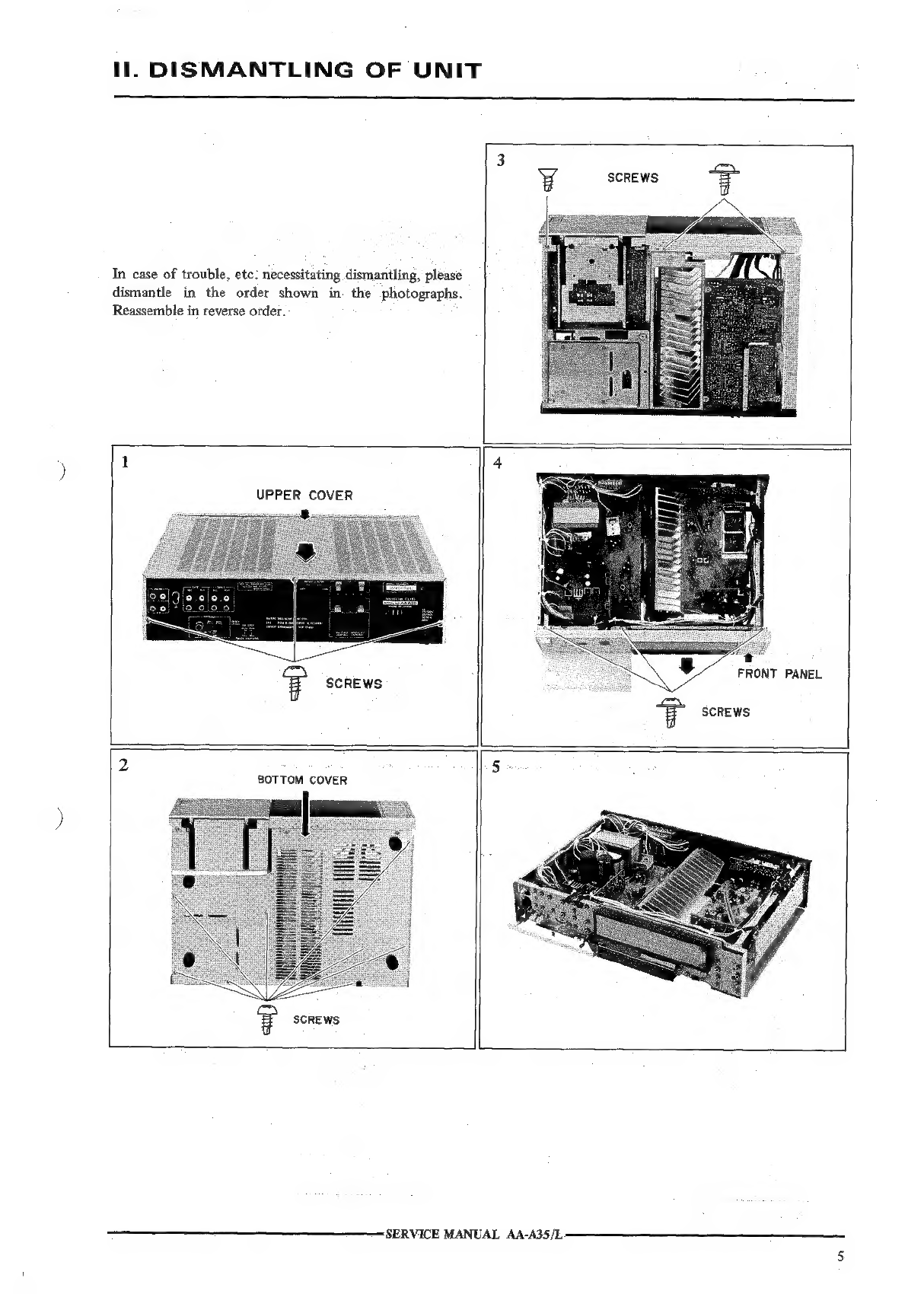
Hf.
DISMANTLING
OF
UNIT
..
5
MW.
CONTROLS
..................
6
Iv.
PRINCIPAL
PARTS
LOCATION
...
eh
hindary
sane
acca
Oo]:
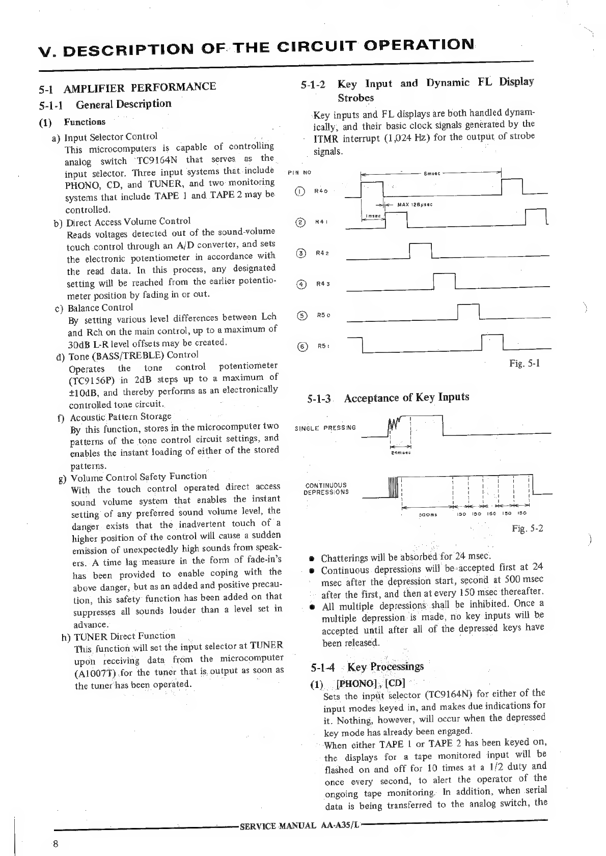
V.
DESCRIPTION
OF
THE
CIRCUIT
OPERATION
..................
8
5-1
AMPLIFIER
PERFORMANCE
.
8
5-2.
TUNER
PERFORMANCE...
........
0...
cee
cee
eee
ot
VI.
AMPLIFIER
SECTION
ADJUSTMENT
.................00.0000.
14
6-1
THE
INSTRUMENT
CONNECTION
...........2.--5.00000.
14
6-2
MAIN
AMP
PC
BOARD
ADJUSTMENT
POINTS..............
14
6-3.
POWER
LEVEL
METER
ADJUSTMENT................-...
14
VII.
TUNER
ADJUSTMENT
.........
006
c
cece
cece
cee
ene
15
7-1
THE
INSTRUMENT
CONNECTIONS
...............-000005
15
7-2.
TUNER,
FRONT
END,
MPX
PC
BOARD
ADJUSTMENT
POINTS
...
16
7-3
HOW
TO
CALL
THE
PRESET
FREQUENCY
FOR
THE
TUNER
ADJUSTMENT
17
7-4
FM
SECTION
ADJUSTMENT..........-....-05
acted
.
18
7-5.
LW
SECTION
ADJUSTMENT......
ees
.
19
74
AM
(MW)
SECTION
ADJUSTMENT
ie
219
Vil.
PC
BOARD
TITLES
AND
IDENTIFICATION
NUMBERS............
20
For
basic
adjustments,
measuring
methods,
and
operating
principles,
refer
to
GENERAL
TECHNICAL
MANUAL.
‘SERVICE
MANUAL
AA-A35/L