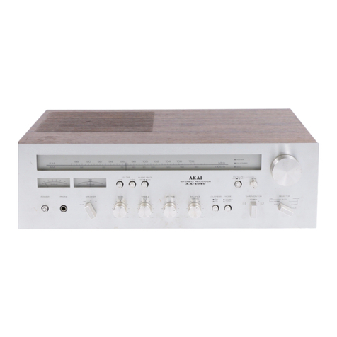
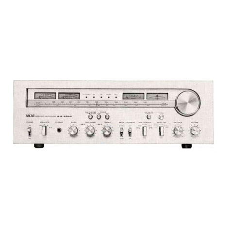
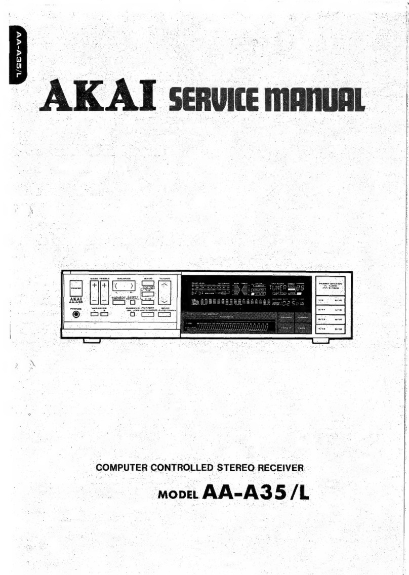
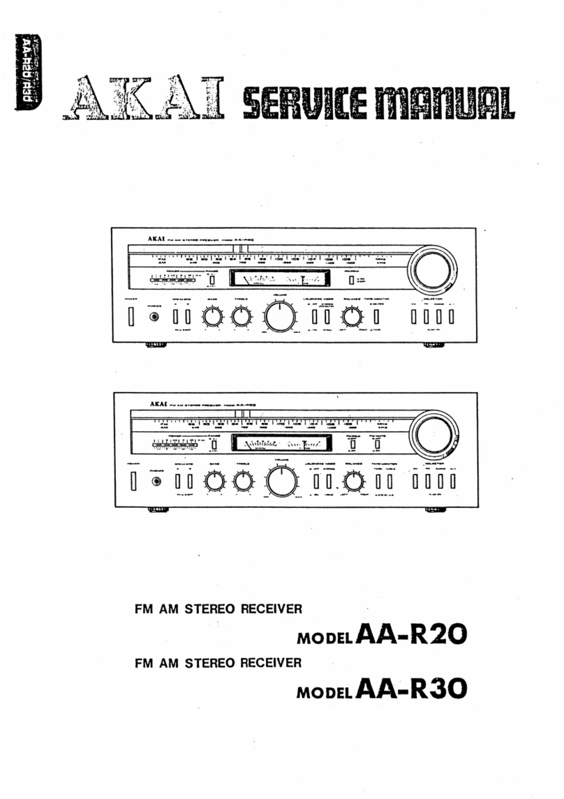
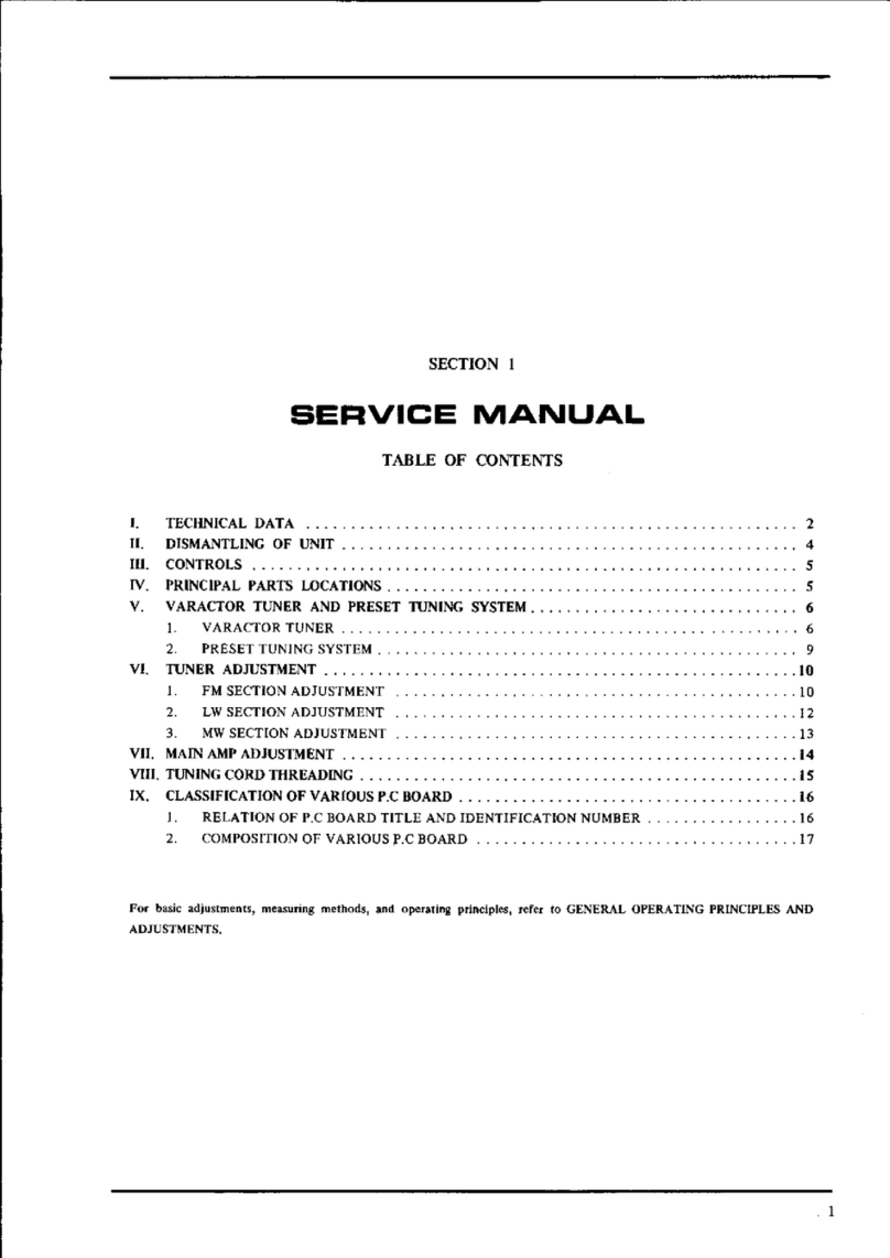
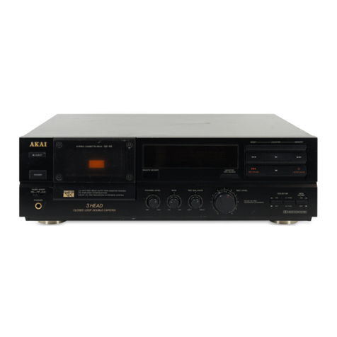
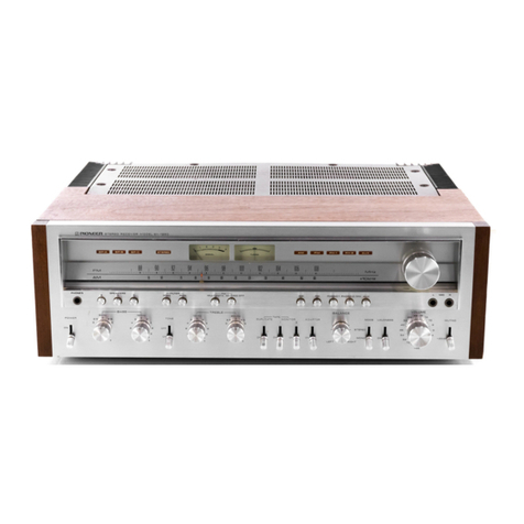
Akai AA-R22/L User manual

A
·.:.
,r
:
it•
"
i
. . '
ALU
t::====~
STEREO RECEIVER
SERVICE
fflADUAl
.:.::
::.:.:;·~.~:1~:~.::~
I;:
~~r;~:
~::
2
_-=
,~
-~-~~-~~-
· •
·:~~~
-
<'::
:~~:
&::_,:_i_igs-;
~?~
/_\_·
MODEL
AA-R22/L
MODEL
AA-R32/L
MODEL
AA-R42

ABBREVIATIONS FOR SERVICE MANUAL
MODEL
AA-R22/L,
AA-R32/L,
AA-R42
ABBREVIATION
A-SW
CK
C-MOS
CPU
fL
FLO
fR
GND
H
INT
L
L
LD
LPF
LSB
MSB
NC
PIN
PLL
POUT
R
ST
SW
SEG
vco
XT
EXPLANATION
Analogue SWitch
ClocK
Complementary Metal Oxide Semi-conductor
Central Processor Unit
Local oscillator Frequency divided
by
PLL factor
Fluorescent Display
Reference Frequency divided by PLL factor
GrouND
High (referring
to
voltages)
INTerrupt (terminal)
Left
Low (referring
to
voltages)
Lock
out
Detection terminal
Low Pass Filter
Least Significant Bit
Most Significant Bit
Not
Connected
Programmable
counter
INput terminal
Phase Lock
Loop
Programmaole
counter
OUTput
terminal
Right
STrobe
SWitch
SEGment
Voltage Controlled Oscillator
Crystal controlled connection Terminal

AA-R22/L
AA-R32/L
AA-R42
STEREO
RECEIVER
MODEL AA-R22/L
MODEL AA-R32/L
MODEL
AA-R42
THIS
MANUAL
IS
APPLICABLE
TO
BOTH
SILVER
AND
PEARL
SHADOW
PANEL
MODELS
SECTION 1 CIRCUIT OPERATION DESCRIPTION . . . . . . . . . . . . 1
SECTION 2 MODEL AA-R22/L SERVICE MANUAL
...........
33
SECTION 3 MODEL AA-R32/L, AA-R42 SERVICE MANUAL
....
47
SECTION 4 PARTS LIST
..................................
75
SECTION 5 SCHEMATIC DIAGRAM
........................
98

SAFETY
INSTRUCTIONS
SAFETY CHECK AFTER SERVICING
Confirm
the
specified insulation resistance between power cord plug prongs and externally exposed parts
of
the set is
greater than 10 Mohms,
but
for equipment with external antenna terminals (tuner, receiver, etc.) and
is,
intended for
[g
or
[A],
specified insulation resistance should be more than 2.2 Mohms (ground terminals, microphone jacks,
headphone jacks. line-in-out jacksetc.)
PRECAUTIONS
DURING
SERVICING
1.
Parts identified
by
the
.&.
symbol parts are critical for safety.
Replace only with parts number specified.
2.
In
addition
to
safety,
other
parts and assemblies are specified for conformance with such regulations
as
those
applying
to
spurious radiation. These must also
be
replaced only with specified replacements.
Examples: RF converters,
tuner
units,
antenna
selector switches, RF cables, noise blocking capacitors, noise
blocking filters, etc.
3.
Use
specified internal wiring.
Note
especially:
l)
Wires covered with
PVC
tubing
2)
Double insulated wires
3) High voltage leads
4.
Use
specified insulating materials for hazardous live parts. Note especially:
1)
Insulation Tape
2) PVC tubing
3) Spacers (Insulating Barriers)
4) Insulation sheets for transistors
5) Plastic screws for fixing microswitch (especially in turntable)
5. When replacing
AC
primary side components (transformers, power cords, noise blocking capacitors, etc.), wrap
ends
of
wires securely
about
the terminals before soldering.
6. Observe
that
wires do not contact
heat
producing parts (heatsinks, oxide metal film resistors, fusible resistors,
e1c
.).
7.
Check
that
replaced wires
do
not
contact
sharp edged
or
pointed
parts.
8.
Also check areas surrounding repaired locations.
9.
Use
care
that
foreign objects (screws, solder droplets, etc.)
do
not
remain inside
the
set.

SECTION
1
CIRCUIT
OPERATION
DESCRIPTION
TABLE
OF
CONTENTS
I.
OUTLINE
OF
AA-R SERIES SYSTEM . . . . . . . . . . . . . . . . . . . . . . . . . . 2
l.
ACCEPTANCE
OF
INPUT
SELECTOR
DATA
. . . . . . . . . . . . . . . . . . 2
2.
FL
DISPLAY
. . . . . . . . . . . . . . . . . . . . . . . . . . . . . . . . . . . . . . . . . 2
3.
SELECTION
OF
INPUT
SIGNAL..
. . . . . . . . . . . . . . . . . . . . . . . . . . 2
4.
VOLUME
CONTROL . . . . . . . . . . . . . . . . . . . . . . . . . . . . . . . . . . . . 2
5.
TONE
CONTROL . . . . . . . . . . . . . . . . . . . . . . . . . . . . . . . . . . . . . . 2
6.
LONG-TIME
BACK-UP
BY
CAPACITOR . . . . . . . . . . . . . . . . . . . . . . 2
11.
OPERATION
OF
AMPLIFIER
SECTION
CONTROL
IC
AA-
I00
PERIPHERAL
CIRCUIT
. . . . 3
1.
AA-100 PERIPHERAL
BLOCK
DIAGRAM
. . . . . . . . . . . . . . . . . . . . . 3
2.
AAIOO
TERMINALS DESCRIPTION . . . . . . . . . . . . . . . . . . . . . . . . . 5
3.
DISPLAY
DATA
. . . . . . . . . . . . . . . . . . . . . . . . . . . . . . . . . . . . . . 6
4.
DIGIT OUTPUT
OF
AA-100
. . . . . . . . . . . . . . . . . . . . . . . . . . . . . . . 7
5.
DESCRIPTION OF
INPUT
SELECTOR. . . . . . . . . . . . . . . . . . . . . . . . 8
6.
OPERATION
OF
ELECTRONIC
VOLUME
CONTROL
AND
TONE
CONTROL
10
7.
THE
STATUS
THAT
WILL
BE
ESTABLISHED
WHEN
WHEN
RESET
BUTTON
IS
PRESSED
17
8.
RESET
STATUS
WHEN
POWER
IS
ON
.......................
17
9.
HOW
TO
MAKE
LETTERS . . . . . . . . . . . . . . . . . . . . . . . . . . . . . . . .
18
ffl.
OPERATION
OF
TUNER
SECTION
CONTROL
IC
AT-600
PERIPHERAL
CIRCUIT
. . . . 20
I.
BLOCK
DIAGRAM
OF
AT-600
PERIPHERAL . . . . . . . . . . . .
.....
20
2.
AT600
TERMINALS
DESCRIPTION
.........................
22
3.
KEY
MATRIX
AND
TIMING
CHART OF
SIGNAL
FOR
DISPLAY
SELECTION
BLANK
PERIOD . . . .
23
4.
FREQUENCY
DISPLAY
SEGMENT
DATA
....................
23
5.
BLOCK
DIAGRAM
OF
PLL
IC
TC9125P INTERIOR
AND
DESCRIPTION OF
THE
FUNCTION
OF
EACH
TERMINAL . . . .
24
6.
PLL
DATA
FOR
PLL
IC
(TC9125P) CONTROL
.................
25
7.
FREQUENCY
CONTROL
BY
PLL
...........................
27
IV.
AKAi
ZERO
DRIVE
CIRCUIT (AA-R42/R32) . . . . . . . . . . . . . . . . . . . . .
28
I.
IN
THE
BEGINNING
. . . . . . . . . . . . . . . . . . . . . . . . . . . . . . . . . . . .
28
2.
PRINCIPLE
OF
AKAI
ZERO
DRIVE CIRCUIT . . . . . . . . . . . . . . . . .
28
V.
DUAL-POLE
DC
SERVO (AA-R42/R32/R22) . . . . . . . . . . . . . . . . . . . . .
31
----------.SERVICE
MANUAL
AA-R22/L,
AA·R32iL.
AA-R42----------

I.
OUTLINE
OF
AA-R
SERIES
SYSTEM
The AA-R series contains two chips, a micro-computer
(AA-100) for the amplifier section and a micro-com-
puter (AT-600) for the tuner section. They control the
AM
TAP!::
2
TAPE
I
AUX
PHONO
TC91256P
T06l02P
SYNTHESIZER
I·
Volume
INPUT IOdS/step
SELECTOR
( C-MOS) t
Analog
Switch
TC4052
X3
system operations. All controls such
as
input select,
volume, tone control, tuner, etc. which have been done
mechanically
so
far are now done electronically.
Tone
control
section ,I
TC9154P Volume
2d0/step
t-
Serio!
DATA
BUS
A
speker
setector
l
----
AT-600
<:====:i
CPU
for
Tuner
Section Control
AA-100
CPU
for
Amp
Section
COnltOI
0
n
Control keys
for Tuner section
1.
ACCEPTANCE
OF
INPUT
SELECTOR
DATA
The amplifier section input selection
is
in charge
of
AA-100 and the tuner section input selector
is
in
charge
of
AT-600,
but
the band selector also acts as a
function selector for input signal switching, and is in
charge
of
AA-100 which controls AT-600 in order to
stop
all
the operations
of
the tuner section for func-
tions other than tuner and
to
extinguish the display.
2.
FL
DISPLAY
The amplifier-related display and the tuner-related
display consist
of
dynamic lighting
of
duty 1/6
provided by AA-100 and AT-600 respectively.
3.
SELECTION
OF
INPUT
SIGNAL
In
accordance with the buttons, PHONO, BAND,
AUX,
TAPE I and TAPE 2, AA-100 controls the
C-MOS
analog switch (TC4052x3)
to
select the
app.ropriate analog signal.
4.
VOLUME
CONTROL
AA-100 transfers serially the level data corresponding
to the
UP
or
DOWN
action to the volume
lC
to
change the volume level.
A'-,-
--------------------
--~---':>
l,_
___
F_L_◊_IS-Pl-AY
___
_,
Cootrot keyt
for
Amp,
section
Fig.
1-1
AA-R
Series System Block Diagram
5.
TONE
CONTROL
AA-100 transfers serially the data corresponding to
the + or -action
of
the
BASS
and TREBLE
to
the
bass
or
treble
IC
to
change the step.
Since the serial data include the data for chip selec-
tion, the data transfer bus
to
the volume
IC,
bass
IC
or treble
IC
uses in common 3 bus bars, DATA,
CLOCK
and STROB.
6.
LONG-TERM
BACK-UP
BY
CAPACITO.R
AA-100 and AT-600, micro-computers for C
MOS
processing, have very low current consumption in
hold mode, thus enabling long-term back-up
:iy
a
capacitor to be realized.
This provides the last-setting memory which
main-
tains the prior status when the power
is
OFF.
However the volume position
will
be
reset at -26
dB
in
order to protect the speaker, even if the power
went
off
at a volume level higher than the prescdbed
level
of-26
dB.
-------------SERVICE
MANUAL
AA-R22/L, AA-R32/L,
AA-R42-------------
2

t5V
ICI
VOLUME 8
TONE
CONTROL -I -
AA-100
-
~-6V
>
+6V
~
0
AT-600@
HOLD) :
~HOLD
T
i-~
r~
r~
-
I
16
I
16
I
16
0
,,
TUNER
KfY
MATRIX (BAND) 4 BAND 0
""Cl
m
t ..J
.,.
t'r1
II
~
~~TSTROB
2
:,:,
R30
....,
~
Ul
1-.~
CLOCK
3
>,::l
"'
.,.
:ill
~
8 -
DATA
4
::c:
<I)
t'Tj
A•
I~
ui.
:,:,
-
I-
> 0
Cl
82
j§
t""
2
A2
u_
-29V
0:,
POWER OFF MANAGE -9V
t""
0 0
V)
~R2:
trJ
0
~
e,
.,
"'
33
POf
.,,
:-0
C)
" i FLO DRIVE
~
< RIO
osc
L..-
-
-
+6V
Cl7
n
"'
..
"'
i 0 _l>
m
:::
ii!
u
SEG
9 -
d >
a:
SEG 8
()
s:
~
SEG 7
C')
INT
~
·c:
:J
SEG 6
)>
,,
~
AT-600[
2 "-
SEG
5
I RESET
31
Q:
)>
!:
0
~
.
u.
u
<(
I
.,,
~
~
....
-
N
I-
o m
?
"Tl
XOVT
z
w
qci'
:I!
f
(!)
ell
"'
-
x,.
<I)
I
N
---
"tJ
(I)
.,.,
I
N
? > I mm
~
I + IC9
LBl294
II
()
►
-
►
0 I
~
0 •
-..;
..
"'
I
,,_
N
(I)
I
....
19
18
17 16
14
12
ii
10
9 • 1 :cO
,s· I
---
::r-
0 I 2 3 4 5 6 7 8 9
10
m2
(I)
I
SEG
....
f::.
L
__
--
--
II()
5:!l
FLD
0
07
06
00
04
03
l>o
()
:,;-
T,
DIGIT SIGNAL
G,
G2
G3
G4
Go
r-2
0 IC6
LB1294
13
23
26
24
48
FLO
PCB
;;;·
(JQ
FLO
DRIVE
()..;
....
3
-II
,,--,
IIO
:>
..
-
()r-
~
Iv
SR2i
I 7 C
Iv
!SRI -
--
~
_,
l"""'
+5V
·29V
..;
w I
'-'

.j;,.
V,
t'll
~
?S
t'll
;i::
~
r.::
>
r-
>
>
"Tl
~
<li5'
N
? w
> >
~
:;:,
~
..,,
~ 0
r 0
>
'"ti
<1>
>
...,
~
'Ci'
::,-'
N
~
a
a,
0
n
:,;-
0
p;·
fl<I
...,
p:,
3
-
>
>
,,
w
t.J
?
(~
'-'
+5V
r
AT-600
HOLO)-E--------,4
TUNER
KEY
MATRIX
(SANDI---------{-~
-
6V
o-----.-(
t6Vi
INPUT
SELECTOR
_·
POWER OFF MANAGE
"f=
-~··
" " u
o
~
R46
*
+5VO--+-+..M--
➔~
s~
i
~
~
,_
A•
I~
_J
UJ
"'
"
"'
z
0
;::
u
z
::,
u.
INT
RESET
Xour
~7)
x,.
KEY
BOAR0~),(2)
PCB
_______
_
~3~uME
~85~:E
~EMORY
~ADER
I
•
I~
I
L--
-
011
.,.
013
•••
.,.
IC/
AA-
iOO
t (2~T,
DIGIT
SIGNAL
SEG10
SEG•
SEGa
SEGT
:lJ
SEGo
u.
"'
SEGo
ii'.
SEG
◄
i:!I
SEG•
i3
,_
z
uJ
::.
"'
4J
"'
SEG2
SEGt
SEGo
VOLUMES
TONE
CONTROL
...
...
RH
~
IC3
L81290
FLO
DRIVE
IC4
1/2
LBl290
"
"
0
~
:It
..
FLO
DRIVE
6V
+35V
•••
[e~l~f
"'
~~J-~
=:
..
..----'-'-=-"'-'-=-""-=..J.=-'-'-=--=-"'-.=;...=...,:.::..icc....i:;:c.,.;:....L;_.i.;:_,=.J=---=....7
FLO
1
G,
G2
G•
G•
Go
L____
J"
-'"
J••
-I"'
·
112
----~
______
_j
KEY BOARD(!) PCB

2.
AAlOO
TER..'1INALS
DESCRIPTION
No. Terminal Description
Function
1
NC
2 STROB
Output
Control
Signal for Elect.
VR
and
TONE
3 CLOCK
Output
at
ACTIVE
"H"
4 DATA
5
CART
(SEGll)
Output
"H"
when
phono
6
SEGl0
7 SEG9
8 SEG8
9 SEG7
IO
SEG6 SEGMENT
DAT
A for Display
11
SEGS
12 SEG4
Output
at
ACTIVE
"H"
i
13
SEG3
14 SEG2
15
SEGl
16
SEGO
17 TS
18
T4
DIGIT Signal
19 T3
Output
at
ACTIVE
''H"
I 20 T2
21
GND
i 22
Tl
DIGIT Signal
! 23
Kl
24
K2 KEY
Input
I 25 K3
Input
at ACTIVE
"H"
: 26
K4
I 27
XIN
Clock OSC Coil I
28
XOUT
29
CK
unused i
I
30
TEST unused
31
RESET Reset
at
ACTIVE
"L"
I
32
INT
Interrupt
Signal
33
POF
Power
OFF
at ACTIVE
"H"
i
34
A2 FUNCTION
SW
Select Signal
35
82
(Bl,
Al)
.........
TUNER,
PHONG, AUX
I
36
A3 (B2,
A2)
.........
Tape I
I
37
B3
(B3,
A3)
.........
Tape 2
38
Al
Output
at
ACTIVE
"H"
39
Bl
40
BAND
Output
"H''
for
Tuner
Band Select when
Phono
and Aux
.
41
HOLD
Output
"H"
for HOLD
of
AT600
42
Vee
+SV
-----------SERVICE
MANUAL
AA-R2~/L, AA·R32/L,
AA-R42-----------
5

3. DISPLAY DATA
Segment data
output
(example: SEG 10
output
when VOLUME 10, TREBLE
IO
and BASS
IO
are lit)
H: LIGHTING
L:
EXTINGUISHING
l~alj
TS
(Grid
5)
T4
(Grid 4) T3 (Grid
3)
T2
(Grid 2)
Tl
(Grid
1)
iSegment Pin Pin J
!
17 18 19
20
I 22
Data
No. No.
1
I SEG
11
5 I
I SEG
IO
6
VOLUMEl0
TREBLE +IO
BASS
+IO
I
SEG9
7 BALANCE VOLUME9 TREBLE
+8
BASS +8
SEG 8 8 FADER VOLUME VOLUME 8 I TREBLE +6 BASS +6
I SEG 7 9 Q 0 VOLUME 7
M2
TREBLE +4 BASS +4
I
SEG6
10 VOLUME6 Ml TREBLE
+2
BASS +2
! I
I
SEGS
11
DUB
Q_Q) VOLUME 5 Frame
of
2
+--
1 ACOUSTIC
I
SEG4
12
I
VOLUME4
ACOUSTIC I
TREBLE-2
BASS-2
I I
SEG3
13
VOLUME3
TREBLE-4
BASS-4
i SEG 2 i 14
AUX
VOLUME2
TREBLE-6
BASS-6
SEG I
15
TUNER
VOLUME I PASS LINE
TREBLE-8
BASS-8
SEGO
16
PHONO i VOLUME0 BALANCE
TREBLE-IO
BASS-IO
-----------SERVICE
MANUAL
AA·R22/L, AA-R32/L,
AA-R42------------
6

4. DIGIT OUTPUT
OF
AA-100
PIN
NO.
of
AA-100
'8)1NT
I I 2 3 4 5 6
I I
:,
I
:1
@ Tl I
I I I L
I
11
I
@
T2
I I
I I
.____.....__
_
__;_
____
-'--
_
__,!
I I
@
T3
I I
I
I
®
T4
I
I
I
I I
@
T5
~
BLANX
PERIOO
1.67 x 6 =
IOmsec
Interrupt request
is
made at the repetition rate
of
1.67 msec by the gate oscillator connected to the
INT
terminal and interrupt processing
is
carried out.
Synchronized with this interrupt, digit output with
the timing
as
shown
in
Fig.
1-4
is
obtained at
Tl
to•
TS.
With the interrupts
of
1.67 msec each, the digit data
of
1
is
output for one bit only in the set
Tl
to TS,
and this
is
repeated 5 times. Then, every bit
is
pro-
vided with one O section, and then this cycle
of
6
interrupts in total
is
repeated.
Fig.
1-4
Digit Output Timing Chart
All
the digits
of
key reading and dynamic fluorescent
display are specified by this digit data.
All
the O sections are provided at the
6th
section in
order to match the display
duty
cycle
of
the
tuner
micro-computer AT-600, and no display
or
key
reading
is
available at this section. (AA-100
has
only
Tl
to
TS
while AT-600 has
Tl
to T6, and therefore,
one dummy section without
output
is
prc¥ided to
meet the AT-600 duty cycle.)
------------SERVICE
MANUAL AA·R22/L,
AA-R32/L,.AA-R42------------
7

5. DESCRIPTION
OF
INPUT SELECTOR
CPU
FOR
TUNER
AT-
600
POF
[
REC
TAPE I
PB
[
REC
TAPE2
PB
ICI5
TC4052BP
AA
-
100
ICl6
TC4052BP
TC4052BP
TRUTH
TABLE
CONTROL
"ON"
INPUT
B A SWITCH
L L
So
L H
S1
H L 52
H H
S3
I
B3
A3
ICl7
TC4052BP
TC4052BP
Fig.
1-5
Block Diagram
of
Input
Switching
Sectio1
-------------SERVICE
MANUAL
AA-R22/L, AA-R32/L,
AA-R42-------------
8

5-1.
FUNCTION
SWITCHING
KEY I
@.
@ ® ®
HOLD BAND
Bl
Al
PHONO H L L H
BAND L L H L
AUX H L H H
Fig. 1-6
Output
Data
of
AA-100
Pin
®to@
Fig.
1-6
shows the data
output
from
PINS
®
to
@
of
AA-100 when each function key
is
pressed. This
data
is
output
when
the
status prior
to
the key opera-
tion
is
available in
other
function. When the PHONO
key
is
pressed,
"H"
is
applied
to
A
of
the
analog
switch TC4052BP
and
"L"
to
B,
SI
is turned ON and
the phono signal is selected. Similarly, when the
BAND SELECTOR key
is
pressed,
"L"
is
applied
to
A and
"H"
to
B,
and S2
is
turned ON, and when the
AUX key
is
pressed,
"H"
is
applied
to
both
A and
B,
S3
is turned ON, and the respective signal
is
selected.
In the case
of
PHONO and AUX,
"H"
is
output
from
HOLD (PIN @ ), and therefore,
the
tuner
CPU
AT-600
is
put in hold mode and the
tuner
operation
is
stopped.
5-2. TAPE MONITOR
SWITCHING
A2
@
82
@----+---~
IC
16
(TC4052BP)
"ON"' SWITCH
St
So
S2
5 V
0 V
5 V
0 V
Fig.
1-8
Output
of
AA0100
Pin@,
® (TAPE
I)
Fig.
1-8
and Fig.
1-9
show the
output
of
A and B
and the operation switch timing chart
of
the.analog
switches 1Cl6 and
17
(TC4052BP) when TAPE 1 or
TAPE 2 keys are pressed.
In both cases, the control
data
sections
of
A=
"L"
and B=
"L"
are provided to operate the dummy
switch S0
so
that no oscillating loop due to the short-
circuit
of
the
REC
and
PB
lines can be created.
HOLD
@------------
5 V
0 V
5 V
0 V
~-----'""
40msec,.I
...
__
_
BAND~
Bl
Al
------------sv
--
0 V
5 V
@---------
0 V
Fig.
1-7
Output
Data
of
AA-100 Pin ®
to
@
(When press the BAND key)
If
the same function key is pressed a second time, no
change occurs
in
the
output
of
Pins ®
to
@
of
AA-100, except
that
if
the BAND SELECTOR key
is
pressed repeatedly in tuner mode, the pulse
of
40 msec
is
output
at Pin ® while the S2 (switch for
tuner) ON data remains unchanged
at
Pins @
and
® as shown in Fig. 1-7. That is, it will turn
ON
the
BAND SELECTOR key equivalent
of
the
tuner
key
matrix and the band
is
switched
in
the sequence
...
FM,
LW,
MW,
FM
...
A3
@
B 3 ®
----;-----1
IC16(TC4052BPl
..
ON"
SWITCH s,
So
S2
5 V
0 V
5 V
0 V
Fig.
1-9
Output
of
AA-100
Pin®,
@ (TAPE 2)
------------SERVICE
MANUAL AA·R22/L, AA-R32/L,
AA-R42------------
9

6. OPERATION
OF
ELECTRONIC VOLUME CONTROL
AND
TONE CONTROL
6-L
OPERATION
OF
ELECTRONIC
VOLUME
CONTROL
AA-100 has been given
the
functions
of
controlling
the electronic volume and electronic tone
control
ICs.
VOLUME, BASS and TREBLE control
ICs
are
controlled
by
the
serial
data
from Pins ® to
of
AA-100. There are 3 data bits: DATA, CLOCK and
STROB. The
data
bit
includes the codes, C0, C1 and
C2, for chip selection, and by connecting the terminal
of C0, C1 or C2,
''L"
to
(-)
and ''.H" to
(+),at
each
control IC, reception
or
non-reception
of
incoming
serial data can be selected.
For
the VOLUME IC, all
DATA
CK
ST
VOLUME
ICII
TC9154P
AA-
100
6-2.
SERIAL
TRANSFER
DATA
VOLUME
-o -10
-20
-30
-40
-50
-60
0 2
the codes are specified as "O".
In
this system,
the
following codes are set for BASS and TREBLE.
.
------
Co@
C1@
C2
(J)
I
i
BASS L H L
TREBLE H L L
Fig.
1-10
Chip select Codes for BASS and
TREBLE
ICs
(TC9156P)
'-------------~+6V
Fig.
1-11
Electronic volume and
tone
control
4 e a L R Co Ct C2
TONE + 6
+5
+4
+3
+2
+ I 0
··I
-2
-3
-4
5
-6
L R
Co
c,
Cz
DATA
4 PIN
CLOCK
3 PIN
STR0S
2 PIN
More
tl'l<ln
2so,
sec_
More thon
500p
see
The leading edge
of
the
clock pulse occurs more
than
260 µsec after the data bit
is
set, and at this point,
reception
of
the data takes place. At the trailing edge
of
the clock pulse, the data bit sets the
next
data.
When
this
is
repeated for
18
bits, the clock
is
turned
I I I
110
µ sec
c>j
!
1.,
7Q)S6'..£__
Fig.
1-12
Serial Transfer
Data
OFF
and after 110 µsec the pulse
of
70
µste
is
output,
and the
IC
chip selected by C0, C
1
or
(2
is
set
to
the
value corresponding
to
the data takei
in.
In the case
of
VOLUME, the
data
of
the 13th bit
is
not
used,
but
O
is
always
output.
-------------SERVICE
MANUAL
AA·R22/L,
AA-R32/L,
AA-R42-------------

6-3. COMPOSITION OF VOLUME
IC
TC9154P
AND
TONE CONTROL (BASS, TREBLE)
IC
TC9156P
6-3-1. Internal Block Diagram ofTC9154P (Volume)
DATA
18
BIT SHIFT REGISTER
CLOCK
5 4 3 2 I
STROB
L-OUT1
CK
L-IN1
:r
::c
u u
I-
I-
<(
'.3
0:
..J
Q.
~
I-
I-
Ii.I
<(
Cl)
I-
::::;
CD
"'z
,_
,_
a:, Ii.I
'0
I-
~!;i
CK
CK
A-GND
CK
CK
L-
INz
:r
u
I-
0:
<(
0:
Q. g ..J Q. 0
Wt"-
IJJ<(
I-
<(
1-:::>
I-
Ill:::>
v,z
iii
z
Ii.I
U)
a:iw
Cl)
I-
~ ~
.,,
I-
(\.I<(
L-
OUH
6
!--------------'
'--------------ll
1R-£:lUT2
Fig. I
13
Internal Block Diagram
ofT:9
154P
-------------SERVICE
MANUAL
AA·R12/L,
AA·R32/L,
AA-R42-------------
11

6-3-2.
Attenuator
of
TC9l
54P
RI
RI=
50K
OHMS
R2=20K
OHMS
The
attenuator
consists
of
diffused resistors and
analog switches. Attenuator
.1
attenuates OdB to
60dB in steps
of
IO
dB
and Attenuator 2 attenuates 2
to
8dB in steps
of
2dB, thus attenuating O
to
66dB
in
total in steps
of
2dB.
0
____
s_,_1"""'1
IL
OUTz
V
ATTENUATOR 2
Fig. 1-14
Attenuator
ofTC9154P
------------SERVICE
MAt'-iUAL
AA·R22/L, AA·R32/L,
AA-R42-------------
l 2

6-3-3. Internal Block Diagram
ofTC9156P
(BASS, TREBLE)
DATA
18
BIT
SHIFT REGISTER
CLOCK
13
12
II 10 9 8 7 6 5 4 3 2
.STROB
c,
C2
C3
~
~
:::,
:::,
u u
a::
a:
0 u
:i:
:r:
u u
I-
I-
< <
...J
...J
~
....
II)
a:)
,..,
,..,
Fig.
1-1
S Internal Block Diagram
ofrC9156P
-------------SERVICE
MANUAL
AA·R22/L,
AA-R32/L,
AA-R42-------------
13

6-3-4. Variable resistor
of
TC91S6P
The variable resistor consists
of
diffused resistors and
analog switches.
R:
I OOK OHMS I
TYP}
+6
--------
-6
R/L-2
Fig.
1-
16
Variable Resistor
of
TC9 I56P
------------SERVICE
~ANUAL
AA-R22/L, AA-R32/L,
AA·R42---------------
14

6-3-5. Operation
By entering optional attenuation data from the
DATA, CLOCK or STROB tenninal, the internal
attenuator
is
set. The data stream consists
of
18
bits
as
follows
..
1)
VOLUME
4 5 6 7 8 9
If, for example, the data stream
000100001000011000
is
input
by
the clock from
the data tenninal, the attenuation
will
be
-32dB.
2) TONE Control
10
II
12
13
14 15
16
17
18
Fig.
1-17 Data
of
Volume Control
I+
6 I+ 5 I+ 4 I+ 3 I+ 2 I+ I IO I
-1
I
-2
I
-3
1-4
I
-5
1-6
IL-CH IR-CHICI
CZ
ICJ
2 3 4 5 6 7 8 9
If,
for example, the data stream
000100000000011000
is
input
by
the clock from
the data terminal, the position will be +3.
3) The data stream taken in
is
synchronized with the
STROB signal to set the attenuator. (same for
VOLUME and TONE controls)
Example: Volume
IC
DATA
-16d8
-18dB
10
11
12
13
14
15
15
17
18
Fig. 1-18 Data
of
Tone Control
- 2
OdB
.__
__
__,
-22d8
CLOCK
_.....J1
....
m11
......
1111
.....
rn1......
un
.....
11
_ ......
111
.....
1111
.....
1111
......
1111-1111_.....,,11-11111-mrn
......
111-1111"'--11
__
__.jJ.U.1111=1111=1111=111LW.1111
__
STROB
CHANGE
OF
ATTENUATOR
-16d8
-18d8
-20dB
-22d8
Fig. 1-19 Relation
of
Data and Attenuator
------------SERVICE
MANUAL AA-R22/L, AA-R32/L,
AA-R42------------
l5

6-3-6.
UP/DOWN
Operation
of
VOLUME
Control
The VOLUME varies
in
steps
of
2dB each from
OdB-
to 66dB and
the
step
OQ
totalling 35 electronic steps.
(IO
display steps for
FL
display)
I)
Step
by
pressing
of
VOLUME Control
a.
The volume moves
UP
or
DOWN
one step
at
a time, thus changing the display accordingly.
Pressing VOLUME during the BALANCE disp-
play will only switch
to
the VOLUME display
at
the existing value without changing it.
b. No action will occur at
MAX
or
MIN even
if
further
UP
or
DOWN
action
is
attempted.
2) Continuous pressing (Holding down the key)
a. After the first 2dB step, the second 2dB step
occurs after 500msec and subsequently changes
in 2dB steps occur every l70msec, and the
display follows. But
if
the pressing
is
started
during
the
BALANCE display, the first display
is
only switched
to
VOLUME
without
changing
its value, and then, after 500msec, the volume
setting
is
changed every l70msec.
b.
The rest
is
the same
as
l
).
6-3-7.
UP/DOWN
Operation
of
BASS
and
TREBLE
Both
BASS
and TREBLE vary in steps
of±5
from
0,
totalling
11
steps.
I) Step
by
step pressing
of
Tone Controls
a.
The value is changed one step
at
a time
to
the
+
or
side.
b. The display
is
changed (point display).
c.
No further action after reaching MAX
or
MIN.
d. All the acoustic memory displays become
invisible and the response line
is
lit.
2)
Continuous pressing (Holding down the key)
a.
After the first one step change, the second step
change occurs after 500rnsec, and then, sub-
sequently the value
is
changed every l70msec.
However
at
the centre value, a 640msec stop
occurs before going
to
the next step. (See
Fig.
1-21)
b. The rest
is
the same as I).
6-3-8.
BALANCE
Control
The Balance value varies in ±
IO
steps from Ototalling
21
steps.
1) Step by step pressing
a.
Change will occur one step at a time to LEFT
or
RIGHT and the display
is
also changed in
sympathy. However operation
of
BALANCE
during the display
of
VOLUME, results in the
change
of
display to BALANCE without change
of
setting.
b.
Once the LEFT or
RIGHT
end
is
reached, no
further action will occur even if the key is
pressed again.
35
STEPS
-5
I
I
:J
I
I
1..-
500
m sec
500msec
+
I70msecX34=
6.28
sec
Fig. 1-20 Volume Change
(when
the
key
is
continuously pressed)
I
I
I
I
I<640m sec
➔
l
I
l~oOm
-;.I
.,,.I
170m
sec
2.33sec
Fig.
1-21
Volume Change
of
BASS and TREBLE
L
,------------------
I
2ISTEPS
CENTER
I
I
I
I
I
I
I
I
I
I
I
I
I
I
I
I
I
I
I
I
R I
I
"1
I
I
IE
i.,soom sec
I
:.,940m sec
4.33
sec
::,,I
c.
After the key
is
pressed for the last time, the
display is switched automatically to VOLUME
after 5 sec. Fig. 1-22 BALANCE Chr1ge
-------------SERVICE
.MANUAL AA-R22/L, AA·R32/L,
AA·R42-------------------
16
This manual suits for next models
2
Table of contents
Other Akai Stereo Receiver manuals