Akai NXT2766 User manual

COLOR TELEVISION
(TS2766)
NXT2766

CONTENTS
Safety Precautions………………………………………………………………………..……
Alignment instruction. ………………………………….…………………………….…….
Debugging instruction …………………………………………….………………………….
Block diagram ……………………………..…..…..…..…..…..…….………….……………
IC Block diagram……………………..……………………….………………………………
Wiring diagram……………………………………………………………………………..…
Exploded view………..…..…..…..…..…..…..…..…..…..…..…..…..…..…..…..…..…..…...
Part list ………………………………………………………..……………............................
Schematic diagram …………………………………………………………………….……..
1
2
3
9
10
14
15
17
36

1
1. SAFETY INSTRUCTION AND GENERAL INSTRUCTION
Before servicing and aligning this equipment, please read the following “X-RAY RADIATION
PRECAUTION” , “SAFETY PRECAUTION” and “PRODUCT SAFETY NOTICE”.
1.1 X-RAY RADIATION PRECAUTION
1)Excessive high voltage can produce potentially hazardous X-RAY RADIATION. To avoid such
hazards, the high voltage must not be above the specified limit. The normal value of the high voltage
of this receiver is below 31.5kV at 1.6A beam current, the high voltage must not, under any
circumstances, exceed 33kV.
2)Each time a receiver requires servicing, the high voltage should be checked following the HIGH
VOLTAGE CHECK procedure in this manual. It is recommended the reading of the high voltage be
recorded as a part of service record. It is important to use an accurate and reliable high voltage
meter.
3)The primary source of X-RAY RADIATION in this TV receiver is the picture tube. For continuous
X-RAY RADIATION protection, the replacement tube must be exactly the same type tube as
specified in the parts list.
4)Some parts in this receiver have special safety-related characteristics for X-RAY RADIATION
protection. For continuous safety, parts replacement should be undertaken only after referring to the
PRODUCT SAFETY NOTICE below.
1.2 SAFETY PRECAUTION WARNING:
Service should not be attempted by anyone unfamiliar with the necessary precaution on this receiver.
The following are the necessary precautions to be observed before servicing this chassis.
1) Since the power supply circuit of this receiver is directly connected to the AC power line, an isolation
transformer should be used during any dynamic service to avoid possible shock hazard.
2) Always discharge the picture tube anode to the CRT conductive coating before handling the picture
tube. The picture tube is highly evacuated and if broken, glass fragments will be violently expelled.
Use shatter proof goggles and keep picture tube away from the unprotected body while handling.
3) When replacing a chassis in the cabinet, always be certain that all the protective devices are put
back in place, such as: non-metallic control knobs, insulating covers, shields, isolation
resistor-capacitor network etc.
4) When replacing parts or circuit boards, disconnect the power cord.
5) When replacing a high wattage resistor (oxiode metal film resistor) on the circuit board, keep the
resistor 10mm (1/2in) away from circuit board.
6) Connection wires must be kept away from components with high voltage or high temperature.
7) If any fuse in this TV receiver is blown, replace it with the FUSE specified in the chassis parts list.
1.3 PRODUCT SAFETY NOTICE
Many electrical and mechanical parts in the chassis have special safety-related characteristics. These
Note:This service manual is only for professional service personnel’s reference. Before
servicing the unit, please read the following items carefully.

2
characteristics are often passed unnoticed by a visual inspection and the X-RAY RADIATION protection
afforded by them cannot necessarily be obtained by using replacement components rated for higher
wattage, etc. Replacement parts which have these special safety characteristics are identified in this
manual and its supplement electrical components having such features are shaded on the schematic
diagram and the parts list.
Before replacing any of these components, read the parts list in this manual carefully. The use of
substitute replacement parts which do not have the same characteristics as specified in the parts list
may create shock, fire, X-RAY RADIATION or other hazards.
2 Alignment items and procedure
The alignment flow chart (see below figure).
3 TEST EQUIPMENT
3.1 AUDIO VOLTAMETER
EEPROM copy
B+ check
Field breadth
and field line
RF AGC adjust
Audio check
Focus adjust and aging
VG2adjust
White balance and sub-bright
H-field and center
field and field breadth
Leave factory state setup
OSD center position
Foucs fine adjust
check
High-handed
Filament voltage
X-ray protect
Picture and audio
Sub-brightness
White balance
Color pure and assemble
AV (S.DVD)
The button check
Remote control check
Assemble check
Safety check

3
3.2 OSCILLOGRAPH
3.3 HIGH-VOLTAMETER
3.4 DIGITAL MULTIMETER
3.5 AC ATTACK PULL TEST EQUIPMENT
3.6 SCAN frequency signal generator BT-3
4 Debugging instruction
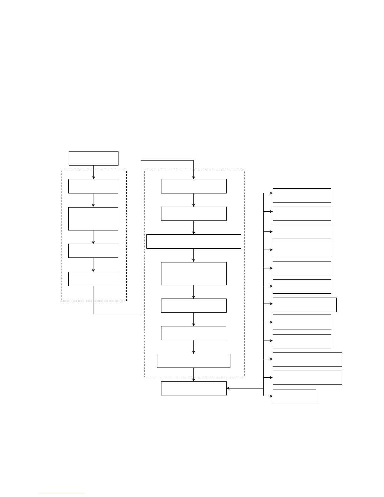
4.1 enter into the factory debugging menu
use to the remote control(RC-A23),follow to the blow model enter into the factory:
DISPLAY →MUTE →MUTE →MUTE →enter into the factory
press “sleep” button for pages upward, press “return” button for pages downward, press “CH+/-” to
select alignment items and “VOL+/-” to adjust volume, press “MUTE” to exit.
If the remote sensor designed for alignment is unavailable, press the following buttons to enter by
using user remote sensor
4.2 B+ voltage adjustment
Check B+ voltage ( negative pole of VD509) by using DC voltmeter DC 200V of 135V±2.
4.3 AGC adjustment
Measure the voltage of RF AGC by connecting digital DC voltmeter with TP3, receive weak signal
(40dBu) and the static AGC voltage of TP1 AGC should be V1=4V±0.2V; the receive antenna signal
(60dBu), adjust the value of P6 RF. AGC of factory menu and the start-control voltage of TP1 AGC
should be V2=3.5V±0.2.if V2>3.5V, then the voltage is -1 or -2,if V2<3.5V, then the voltage is+1 or+2. the
antenna input 100dBu signal, after the picture should not be appeared no-sync , distortion and moire;
input 35-40dBu weak signal ,it should not be appeared distortion and no-sync and sound abnormity
electrophoresis of it.
4.4 White balance and screen-grid voltage adjustment
After enter P5 of factory menu, use remote sensor directly to adjust white balance by pressing the
following digital buttons:
“1”=R.BIAS(+) “2”=G.BIAS(+) “3”=B.BIAS(+)
“4”=R.BIAS(-) “5”=G.BIAS(-) “6”=B.BIAS(-)
press “p-p” button to select picture mode custom→T1→T2→bright→soft→nature→user→custom will
be display on the screen.
The T1 mode has the maximum value of brightness and contrast with all the other items minum. Value of
all the analog are minimum while in T2 mode.
Before adjustment you should set the following items: SUB-BRIGHT=50, R.B=100, G.B=100, B.B=100,
R.D=100, G.D=15, B.D=100
press “P-P” button to select T2 picture mode, press CH+/- to select LINE, press vol+ to let the field
scanning fail to oscillate, adjust the screen-grid potentiometer on FBT clockwise to let horizontal bright
line just appear on the screen; let the value of G.B unchanged, adjust R-B and B-B to let the horizontal
bright line appear white. If the green horizontal line don’t appear firstly, fine-turn the screen-grid voltage,
green and blue just appear. After adjustment press VOL- to obtain normal field scanning mode.
4.5 Receive signal (A7), enter P6 of factory menu, adjustment SUB-BRIGHT to let picture on the screen
micro-bright.
4.6 receive white balance adjustment signal
enter P5 of factory menu, press PP to select T1 picture mode, let the value of G.D unchange, adjust R.D
and B.D to let the white part of the picture appear “white”.

4
4.7 Use white balancer to rectify the white balance under following conditions
color temperature:12000K+8MPCD x =0.270± 0.008 Y=0.283±0.008; dark space: 4.5nit, bright space:
60nit
Note:1. While the colour saturation changed from maximum to minimum, if the dark balance appears
changeable,adjust RY.TV and BY.TV (P12) to let it coincide with white balance.
2. If the dark balance appears changeable while connected with DVD, adjust BY.YUV and RY.YUV
(P12) to let it conincide with white balance.
4.8 line-filed scanning amplitude and linearity and center adjustment and raster correct adjstment.
4.9 receive signal (A28), press the PP button the picture model, set standard adjustment the P1 of
V.SIZE and V.SHIFT and H..PAHSE and V.LINE and VSC, let the P2 coincide with request.
4.10 receive signal (G43), press the PP button the picture model, set standard adjustment the P3 of
V.SIZE and V.SHIFT and H..PAHSE and V.LINE and VSC, let the P4 coincide with request.
4.11 High voltage and filament voltage check
Connect a high-voltage meter between anode cap of picture tube and the ground, measure the filament
voltage using rms voltmeter, set the picture mode to “standard”, the high-voltage: 29KV±1.5KV,filament
voltage: 6.3±0.1Vrms.
4.12 x -ray protection check
Receive local TV signal, set the picture mode to “standard”, shorten the circuit and measure the
value of TP1-TP2, restart the TV 30 seconds after turn off the power source and it should return to
normal.
4.13 AV function check
according to the owner’s manual require, connect to the AV equipment and the AV interface:
VIDEO IN: 1 Vp-p 75OHM AUDIO IN: (-8±3)dBm>47 kOHM
S interface Y IN: 1 Vp-p 75OHM C IN: 0.3 Vp-p 75OHM
DVD Y IN: 1 Vp-p 75OHM Cr IN: 0.7 Vp-p 75OHM
Cb IN: 0.7 Vp-p 75OHM
4.14 AV parts check
incept to standard the TV signal:
a)AV and crossfire and allophone and shake ;
b)The user control function ana picture model
c)The remote control function check;
d)Color pure and converge check.
4.15 leave factory state setup
Picture model (PP) STENDARD
language All the country language
Color system AUTO
C.CAPTION C1
CCD ON MUTE OFF
RECEPTION AIR
AFT ON
MTS AUTO
PASSWORD CLEAR
volume 30

5
4.16 the factory menu adjustment model pre-set
OSD item Pre-set model
P1-60
V SIZE 60HZ field amplitude 63 4.9
V SHIFT 60HZ field center 0 4.9
H-PHASE 60HZ H-center 15 4.9
V LINE 60HZ V-line 15 4.9
V SC 60HZ field S-correct 23 4.9
V COMP field amplitude compensate 7 fixed
L.BLK Left blanking 7 fixed
R.BLK Right blanking 0 fixed
P2-EW-60
COR.SW margin correct 1 Fixed
H.SIZE.COMP High voltage compensate 7 fixed
TILT 60HZ echelon correct 44
DC 60HZ H-amplitude 32
AMP 60HZ pincushion correct 25
COR.TOP 60HZ Top margin correct 4
COR.BOT 60HZ bottom margin correct 3
Receive signal A12, adjust the linearity scanning and
geometric distortion and over-scanning coincide with it
P3-50
V SIZE 50HZ field amplitude 75 4.10
V SHIFT 50HZ field center 0 4.10
H-PHASE 50HZ H-center 10 4.10
V LINE 50HZ V-line 16 4.10
V SC 50HZ field S-correct 20 4.10
P4 EW-50
TITL 50HZ echelon correct 49
DC 50HZ H-amplitude 35
AMP 50HZ pincushion correct 41
COR.TOP 50HZ Top margin correct 6
COR.BOT 50HZ bottom margin correct 10
Receive signal G35, adjust the linearity scanning and
geometric distortion and over-scanning coincide with it
P5
LINE Level bright line 0 0=normal 1= Level bright line
RB Red cut off 100 4.4
GB Green cut off 100 4.4
BB Blue cut off 100 4.4
RD Red driver 100 4.4
GD Green driver 15 4.4
BD Blue driver 100 4.4
P6
RF AGC RF AGC 30 4.3
SUB-BRI Sub-brightness 60 4.4
SUB-CNT Sub-contrast 31 fixed

6
SUB-COL Sub-colour 3 fixed
SUB-SHP Sub-definition 0 fixed
SUB-TINT Sub-tint 28 fixed
P7
VOL.FIL Volume control ADC filter 0 fixed
OSD.COT OSD contrast 5 fixed
OSD.HPOS OSD center 10 fixed
AFT Line AFC loop gain and sync
gate switch 0 fixed
VIF SW IF3=45.75MHZ 3 fixed
SIF SW Sound IF0=4.5MHZ 0 fixed
VIDEO LEVEL VIDEO LEVEL 2 fixed
P8
A2 .SW 0 fixed
GY ANGLE G-Y demodulation angle 0 fixed
V.R TM Filed scan strting time 0 fixed
R/B ANG R-Y/B-Y demodulation angle 8 Fixed
R/B BAL R-Y/B-Ydemodulation
balance 8 fixed
C TRAP Color trap filter 6 fixed
H FREQ H-frequency 16 fixed
C.BPF TEST Color band filter center
frequency 0 fixed
P9
OVER.MOD.SW Selection over-modulation
function 0 Fixed,0=nothing 1=have
OVER.MOD.LVL Adjustment over-modulation
working point 0 fixed
BLK.STR Dark level expand starting
control point 2 Fixed,0=40IRE 2=60IRE 3-OFF
BLK.GAIN Dark level expand gain 2 Fixed,0=MIN 2=MAX
Y.APF Selection color trap filter 1 0=trap filter,1= direct pass(YcbCr&Y/C)
PRE.ADJ Pre-shoot 3 fixed, 0=narrow 3=width
OVER ADJ overshoot 3 Fixed,a 0=narrow 3=width
C.VCO.ADJ Color VCO frequency
adjustment 4 fixed,0-4-7=-120KHZ-0-90KHZ
P10
BRT.ABL.DEF Brightness ABL 0 fixed,0=ABL ON 1=ABL OFF
MID.STP.DEF ABL start control point 0 fixed
BRT.ABL.THR ABL threshold 7 fixed
WPL.OPE White peak limit 2 fixed
V BLK.SW Field blanking switch 0 fixed ,0=nomarl;1=width model

7
FBP BLK SW Horizontal blanking switch 1 fixed,0=inside produce;1=FBP and inside logic “and”
DC REST DC recover rate 1 fixed,0=100% 1=107%
CD.MODE Field frequency division
model 0 fixed,0=auto
P11
CORE GAIN Noise reduction 2 fixed,0=OFF 1=MIN 3=MAX
γ.GAMA r-correct 0 fixed,0=OFF
RGB TEMP.SW RGB DC output
temperature speciality 1 fixed
A.MONI SW Selection pin5 output 1 fixed,1=SAO
SVO OR FSC Selection pin5 output 0 fixed,0=VIDEO 1=FSC(color sub-carrier wave)
CROSS B/W Selection test signal 0 fixed,0=TV
CRAY.MODE Test signal 0 fixed,0=white(75%)1=grey(15%)
P12
BY TV Blue chromatism DC level 8 4.4 adjustment dark white balance(TV/AV model)
RY TV Red chromatism DC level 8 4.4 adjustment dark white balance(TV/AV model)
BY YUV DVD input Blue chromatism
DC level 8 4.4 adjustment dark white balance (DVD input)
RY YUV DVD input Red chromatism
DC level 8 4.4 adjustment dark white balance(DVD input)
S.TRAP.TEST Sound trap filter adjustment 6 fixed
LOW.BRI Min-brightness 28 fixed
LOW.CONT Min-contrast 30 fixed
P13
COL.KILL Achromatic level 7 fixed,0=-30dB 3=-40dB
VCO.FREQ VCO frequency 32 fixed
VM.GAIM VM gain adjustment 0 fixed
VM.DELAY ADJ VM relay time adjustment 0 fixed
VCO TEST VCO adjustment 0 fixed
VPOS-50 50HZ field center voltage
adjustment 15 fixed
VPOS-60 60HZ field center voltage
adjustment 15 fixed
P14
Y GAIN 0 fixed
Y TH 0 fixed
B OFFSET 0 fixed
B WIDTH 0 fixed
C OFFSET 0 fixed
C WIDTH 0 fixed
CAN.V CHIP V-CHIP 0/1 1=CAN.V-CHIP
OPTION

8
AV AV selection 3 AV input select(3=AV1/AV2/S/DVD)
MTS MTS IC selection 1/0 0=nothing,1=72700 2=AN5832
V.OFF.MOTE Turn off model 1 0=discharge,1=close
PWR.MEM Turn on model 0/2 0=standby,1=auto turn on,2=memory
1115 select LV1115 0 fixed,0=nothing;1=have
BLCK GROND No signal background
selection 1 0=nothing 1/3=blue background;2=black background
N/PN South America and North
America selection 1/0 0=south america;1=north america
1115(the unit no use)
VOL.OFFSET 0
GAIN 3
PWM LOGIC 0
AVL MODE 2
AVL DET LEVEL 0
AVL SLOPE 0
PWM SET
PWM.VOL Volume control of PWM set 1 fixed
1-CHIP.VOL Volume control of mono 0 fixed
VOL 1 1% volume control speciality 20 fixed
VOL 25 25%volume control speciality 60 fixed
VOL 50 50%volume control speciality 90 fixed
VOL 75 75%volume control speciality 100 fixed
72700
ALC ALC 1 fixed ,1=ALC ON
VOL Baseband model ,input level
adjustment 0 The unit no use
SAP LEVEL SAP level 1 fixed
SIF.M/BB.M SIF and baseband model 0 fixed,0=SIF MODE 1=BB MODE
5832
AGC 1 fixed
Note:above “/” are the adjustment data for north america, below it are for south america.

9
BLOCK DIAGRAM
IR TX
M3428M1-D48GP
IR RX
MEMORY
N202
M24C08
T101
TUNER
SAWF
PIF
LA76932
I2C BUS LINE
DEFLECTION
VOUT
N301
L
A
78041
HOUT
V302
2SC2539
T301
FBT
CRT
DRIVE CRT
EHV
28V
VIDEO
REM
IF
RF
SIF
CHROMA
R
G
B
POWER
N501
CQ12656RT
A
C 120V
/
110V
110V
A
UDIO
A
MP
A
N7522
14V
H VCC
N503
5V-1
V SWITCH
4053
VIN TV OUT
VIDEO
OUT
AUDIO
OUT
V OUT
A OUT
Y Cr Cb AUDIO
IN
VIDEO
IN
S IN
Y Cr Cb
C
P
U
A SWITCH
4053
MTS

10
MAIN IC
LA76930 BLOCK DIAGRAM

11
Function introduction to pin
pin function Reference
voltage
(V)
pin function Reference
voltage
(V)
1 SIF output 2.28 64 PIF input1 2.86
2 PIF AGC 2.61 63 PIF input 2 2.86
3 SIF input 3.11 62 IF GND 0
4 FM filter 2.64 61 RF AGC output 4.55
5 FM filter/sound output 2.25 60 Video output 2.30
6 Sound output 2.24 59 AFT filter 2.50
7 SIF APC filter 2.24 58 APC filter 2.60
8 IF VCC(5V) 4.92 57 Black level detection
filter
2.50
9 Expanded sound input 2.25 56 Internal video input and
S-C input
2.70
10 ABL 3.21 55 Video, colour and
deflexion power VCC
4.90
11 RGB VCC(8V/18Ma) 8.00 54 Expanded video input
and Y input
2.50
12 R ouput 2.65 53 Colour APC filter 3.40
13 G ouput 2.65 52 Selection video output
and FSC output
2.40
14 B ouput 2.67 51 Cr input 2.50
15 AKB (undo) 2.31 50 4.43 MHZ crystal 2.73
16 Field sawtooth filter to
capacitance
2.16 49 Cb input 2.50
17 Field output 2.34 48 Fast blank-out input 0
18 VCO Reference voltage 1.65 47 R input 1.89
19 H/BUS VCC(5V/27mA) 6.81 46 G input 1.90
20 H/APC filter 2.54 45 B input 1.90
21 H-output 0.28 44 Retrace impulse input 1.20
22 Video,colour and
deflexion ground
0 43 CCD VCC 4.50
23 x -ray protection, low
level availability
5.00 42 CPU GND 0
24 S input detection, high
Level availability
3.50 41 PLL 3.50
25 DVD detection, high
Level availability
6.50 40 reset 4.00
26 IR control input 4.90 39 Button input 0.32
27 AV1/AV2 H=AV1
L=AV2
0 38 TV/AV H=TV L=AV 0

12
28 POWER H=OFF
L=ON
0 37 BL 5.00
29 Turn voltage PWM
output
1.73 36 BH 5.00
30 Mute, high
Level availability
0 35 VDD 5.00
31 I2C DATA 5.00 34 x T2 4.50
32 I2C CLOCK 5.00 33 x T1 2.70
AN7522
Pins function
pin function pin function
1 power 7 GND input
2 CH1+ output 8 CH2 input
3 GND 9 volume
4 CH1- output 10 CH1+ output
5 Stand-by 11 GND (CH2 output)
6 CH1 input 12 CH1+ output

13
FSCQ1265RT

14
WIRING DIAGRAM

1
2
3
45
67
8
9
10
11
12 13
14
15 16
17
18
19
20
21
EXPLODED VIEW

TS2766
PART LIST OF EXPLODED VIEW
NO. DESCRIPTION PART#
1 REAR NAMEPLATE 880-10205-906
2 REAR CABINET 780-E68CG-020
3 SIDE AV BRACKET 870-3B051-022
4 CRT BOARD ASSY 667-TSE30-02
5 COMPONENT SCREW 648-30001-00
6 BRAIDED LINE 123-30001-04
7 BRAIDED PULLING SPRING 838-10401-00
8 CRT FIXED BRACKET 615-10184-00
9 LINE CLASP 742-30032/38-00
10 REAR PANEL 808-1D650-020
11 FRAME 863-6A127U000F
12 LED COLUMN 700-60210-00
13 BUTTON BOARD 667-TS2967-05A
14 CRT CUSHION 868-20175-00
15 FRONT CABINET 611-E66C0J0H4A
16 FRONT NAMEPLATE 808-10783-A1
17 WASHER 868-20217-00
18 SPEAKER 384-40908-B0
19
20 SPEAKER BRACKET 870-30059-00
21 POWER BUTTON 877-60622-00B

PART LIST
PART# DESCRIPTION LOCA.NO.
100-TS27660-10 NXT2766
100-TS27660-01 TS2766
123-30001-04 TWIST WIRE
335-2942R-00U CRT A68CPBB02X01 !
477-12904-00U DEGAUSS COIL DX-29!
488-10012-00 BATTERY 7#(made in china
491-752J0-02 POWER CORD UL !
604-TS27667-00 OWNER'S MANUAL(NEXXTECH,CAN)
611-E66C0J0H4A FRONT CABINET ASS'Y (ABS V0 SILVER WHITE 03
615-10184-00 CRT HOLDER ASS'Y
648-30001-00 COMPOSE NUTS SJ2843-87M6
655-63101-09 (6-PINS) LEAD WITH HOUSING
700-60210-00 LED COLUMN
742-30005-09 LINE TIE
742-30006-09 GRADING TIE
742-30032-00 TIE
742-30038-00 TIE
742-30060-00 POWER CORD CLAMPE
770-40151-40 IMITATEUL1672 22# 400mm BLACK
780-E68CG-020 BACK CABINET ( MOLD BLACK )
808-70239-00 EVA GLUE 150X50X1
838-10401-00 BRAIDED WIARE SPRING
851-24012-11 SCREW SJ2824 ST4X12C-D.Zn
851-24014-14 SCREW SJ2824 ST4X14C-Y
851-24016-14 SCREW SJ2824 ST4X16C-Y
851-24020-14 SCREW SJ2824 ST4X20C-Y
851-24025-11 SCREW SJ2824 ST4X25C-D.Zn
851-24030-14 SCREW SJ2824 ST4X30C-Y
851-53008-31 SCREW SJ2825 ST3X8FT D.Zn
851-53010-31 SCREW SJ2825 ST3X10FT-D.Zn
851-53012-31 SCREW SJ2825ST3X12FT-DZn

851-53012-31 SCREW SJ2825ST3X12FT-DZn
851-54012-31 SCREW ST2825 ST4X12FT-D.Zn
855-A0029-00 SCREW ST4X14
857-10002-09 COTTON FLANNEL
857-10004-00 COTTON FLANNEL
863-80965-01A POLY FOAM (TOP )
863-80966-01A POLY FOAM (BOTTOM )
868-20007-00 SLEEVE
868-20037-00 FIBRE WASHER φ8Xφ3.2X0.5
868-20123-00 RUBBER WASHER
868-20175-00 SUPPORT CUSHION
868-20696-00 FRAME 压BLOCK
870-2B793-00 CRT BRACKET
880-10205-906 BACK PLATE (NXT2766,NEXXTECH)
880-10783-A1 FRONT LOGO (NEXXTECH SILVERY GREY 10C
881-60085 BLANK WARNING LABEL
881-64014-00 TRANSPORTATION LABEL (NXT2766,NEXXTECH)
881-64055-00 WARNING LABEL (NXT2066,NEXXTECH)
881-64056-00
R
EMOTE CONTROL UNIT LABEL (NXT2766,NEXXTECH)
881-80810-00 PASSWORD CARD Nexxxtech
886-31454-290W CARTON BOX (NXT2766,NEXXTECH)
887-20044-01 POWER CORD COVER
887-20171-00 PALSTIC BAG 70-500-0.06
887-21114-04 PALSTIC BAG ( WARNING )
887-21188-00 CLASPER PALSTIC BAG (350X250RED TRANSPARENT
893-10600-11 NUT GB6170-86-M6 D.Zn
667-TS2755-31 MTS BOARD ASS'Y
667-TS2755-31\ MTS BOARD ASS'Y (MANUAL INSERTION )
667-Q2735-31\ MTS BOARD ASS'Y (MANUAL INSERTION )
This manual suits for next models
1
Table of contents
Other Akai TV manuals

Akai
Akai ATE-24D604 User manual

Akai
Akai LTA-26C902 User manual

Akai
Akai 29CTF05BS User manual

Akai
Akai CT-S14MTD-E3 User manual

Akai
Akai LCT2016 User manual

Akai
Akai PDP42Z5TA - 42" Plasma TV User manual

Akai
Akai PT50DL14 User manual

Akai
Akai LTA-26C903 User manual

Akai
Akai 14CNT11BB User manual

Akai
Akai 29CT24FS User manual

Akai
Akai CT-1420ANF User manual

Akai
Akai PDP5006H User manual

Akai
Akai ATE-24014 CNK User manual

Akai
Akai LTC-16RSX3M User manual

Akai
Akai DVLX44C1 User manual

Akai
Akai PDP4273M User manual

Akai
Akai LCT2765TD User manual

Akai
Akai LEA-19H03P User manual

Akai
Akai LTA-26C902 User manual

Akai
Akai 21CTS92FS User manual