AKG SO 40 SNAPON User manual

BEDIENUNGSANLEITUNG . .S. 2
Bitte vor Inbetriebnahme des Gerätes lesen!
USER INSTRUCTIONS . . . . . . . .p. 10
Please read the manual before using the equipment!
MODE D’EMPLOI . . . . . . . . . . . . . . . .p. 18
Veuillez lire cette notice avant d’utiliser le système!
ISTRUZIONI PER L’USO . . . . .p. 26
Prima di utilizzare l’apparecchio, leggere il manuale!
MODO DE EMPLEO . . . . . . . . . . . .p. 34
¡Sirvase leer el manual antes de utilizar el equipo!
INSTRUÇÕES DE USO . . . . . . . .p. 42
Favor leia este manual antes de usar o equipamento!
SO
40 snapon

Seite
1 Sicherheit und Umwelt........................................................................3
1.1 Sicherheit ..................................................................................3
1.2 Umwelt......................................................................................3
2 Beschreibung.......................................................................................3
2.1 Einleitung ..................................................................................3
2.2 Lieferumfang .............................................................................3
2.3
Optionales Zubehör....................................................................3
2.4 Beschreibung.............................................................................3
2.5 Bedienelemente .........................................................................4
3 Inbetriebnahme ...................................................................................5
3.1 Batterie einlegen/austauschen und testen ...................................5
3.2 Betrieb mit Akku ........................................................................6
4 Anwendung..........................................................................................7
4.1 Empfohlene Mikrofone................................................................7
Seite
4.2 Sender anstecken und abziehen . . . . . . . . . . . . . . . . . . . . . . . . . . . . . . . . . 7
4.3 Pegel einstellen . . . . . . . . . . . . . . . . . . . . . . . . . . . . . . . . . . . . . . . . . . . . . 7
4.4 Mikrofontechnik . . . . . . . . . . . . . . . . . . . . . . . . . . . . . . . . . . . . . . . . . . . . . 7
4.5 Fehlerbehebung . . . . . . . . . . . . . . . . . . . . . . . . . . . . . . . . . . . . . . . . . . . . . 8
5 Reinigung
. . . . . . . . . . . . . . . . . . . . . . . . . . . . . . . . . . . . . . . . . . . . . . . . . . . . . . 8
6 Technische Daten . . . . . . . . . . . . . . . . . . . . . . . . . . . . . . . . . . . . . . . . 9
Inhaltsverzeichnis
2
SO 40 snapon

3
SO 40 snapon
1 Sicherheit und Umwelt
1.1 Sicherheit
1. Setzen Sie das Gerät nicht direkter Sonnen-
einstrahlung, starker Staub- und Feuchtigkeits-
einwirkung, Regen, Vibrationen oder Schlägen
aus.
1.2 Umwelt
1. Entsorgen Sie verbrauchte Batterien und Akkus
immer gemäß den jeweils geltenden
Entsorgungsvorschriften. Werfen Sie Batterien
oder Akkus weder ins Feuer (Explosionsgefahr)
noch in den Restmüll.
2. Wenn Sie das Gerät verschrotten, entfernen Sie
die Batterien bzw. Akkus, trennen Sie Gehäuse,
Elektronik und Kabel und entsorgen Sie alle
Komponenten gemäß den dafür geltenden Ent-
sorgungsvorschriften.
3. Die Verpackung ist recyclierbar. Entsorgen Sie
die Verpackung in einem dafür vorgesehenen
Sammelsystem.
2 Beschreibung
2.1 Einleitung
Vielen Dank, dass Sie sich für ein Produkt aus dem
Hause AKG entschieden haben. Bitte lesen Sie
die Bedienungsanleitung aufmerksam durch,
bevor Sie das Gerät benützen, und bewahren Sie
die Bedienungsanleitung sorgfältig auf, damit Sie
jederzeit nachschlagen können. Wir wünschen
Ihnen viel Spaß und Erfolg!
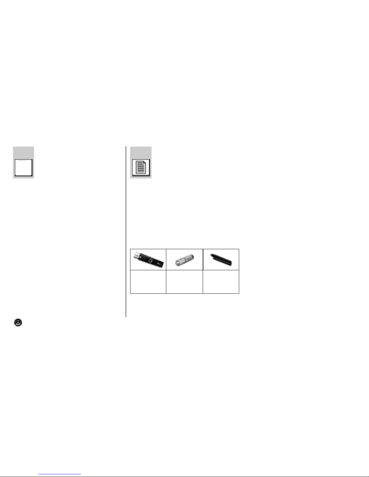
2.2 Lieferumfang
• Kontrollieren Sie bitte, ob die Verpackung alle
oben angeführten Teile enthält. Falls etwas fehlt,
wenden Sie sich bitte an Ihren AKG-Händler.
2.3 Optionales Zubehör
• Optionales Zubehör finden Sie im aktuellen
AKG-Katalog/Folder oder auf www.akg.com.
Ihr Händler berät Sie gerne.
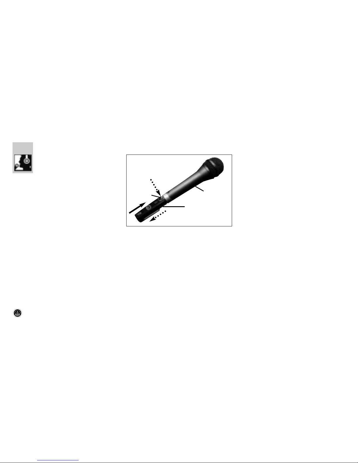
2.4 Beschreibung
Der SO 40 ist ein Miniatursender der Serie WMS 40
microtools, der speziell zum direkten Anstecken an
Mikrofone entwickelt wurde.
Der Sender besitzt einen 3-poligen Standard-XLR-
Stecker, mit dem Sie den Sender direkt an ein
dynamisches Mikrofon (z.B. AKG Emotion-Serie)
oder ein Kondensatormikrofon mit interner Strom-
versorgung (z.B.AKG C 1000 S) anstecken können.
Der SO 40 arbeitet auf einer fixen, quarzstabilisier-
ten Trägerfrequenz im UHF-Trägerfrequenzbereich
von 710 bis 865 MHz.
Die Farbe des Batteriefachdeckels entspricht der
Trägerfrequenz des Senders (siehe Manual Sup-
plement). Sie können den Batteriefachdeckel aber
auch gegen den mitgelieferten schwarzen Ersatz-
deckel austauschen.
1 Sender
SO 40
1 Batterie
Größe AAA 1 Batterie-
deckel
(schwarz)
L
!

2.5 Bedienelemente (siehe Abb. 1)
1 ON/MUTE/OFF: Dieser Schiebeschalter hat
drei Stellungen:
ON: Die Spannungsversorgung für den Sender
ist eingeschaltet.
M: Das vom Mikrofon kommende Audiosignal
ist stummgeschaltet, Spannungsversorgung
und HF-Trägerfrequenz bleiben jedoch einge-
schaltet. Dadurch wird der Empfänger trotz
abgeschaltetem Mikrofon nicht durch andere
Sender gestört.
OFF: Die Spannungsversorgung für den Sender
ist ausgeschaltet.
2 Batteriefach für 1 Stk. 1,5 V-Batterie Größe
AAA (mitgeliefert).
3 Kontroll-LED: Diese LED zeigt den Lade-
zustand der Batterie an.
LED leuchtet beim Einschalten kurz auf und
erlischt wieder: Batterie in Ordnung.
LED leuchtet konstant: Batterie in ca. 60 Mi-
nuten erschöpft.
4 Eingangspegelregler: Stellt die Empfindlich-
keit des Audioeingangs ein.
5 XLR-Stecker: 3-poliger Standard-XLR-Stecker
(weiblich) zum direkten Anschluss des Senders
an ein Mikrofon mit 3-poligem XLR-Stecker.
Siehe auch Kapitel 3.
6 Entriegelungsknopf für den XLR-Stecker
4
SO 40 snapon
Abb. 1: Bedienelemente SO 40

3 Inbetriebnahme
3.1 Batterie einlegen/austauschen
und testen (siehe Abb. 2)
1. Drücken Sie den Schnapphaken am
Batteriefachdeckel (1) nach unten.
2. Ziehen Sie den Batteriefachdeckel (1) nach
unten vom Sender ab.
Wichtig!
Der Schaumstoffpolster an der
Innenseite des Batteriefachdeckels
(1) fixiert die Batterie in ihrer Position.
Entfernen Sie den Schaumstoff-
polster nicht, da die Batterie anson-
sten nicht richtig im Batteriefach
fixiert ist und Klappergeräusche ver-
ursachen kann.
3. Wenn sich eine leere oder defekte Batterie im
Batteriefach befindet, nehmen Sie diese her-
aus.
4. Legen Sie die mitgelieferte bzw. neue Batterie
(2) wie in Abb. 2 gezeigt in das Bateriefach ein.
5. Stellen Sie den ON/MUTE/OFF-Schalter (3) auf
ON.
Die Kontroll-LED (4) blitzt kurz auf. Wenn die
Batterie in gutem Zustand ist, erlischt die
Kontroll-LED (4) wieder.
Wenn die Kontroll-LED (4) zu leuchten beginnt,
ist die Batterie in ca. 60 Minuten erschöpft.
Tauschen Sie die Batterie möglichst bald gegen
eine frische aus.
Wenn die Kontroll-LED (4) nicht aufblitzt, ist die
Batterie erschöpft. Legen Sie eine neue Bat-
terie ein.
6. Schieben Sie den Batteriefachdeckel (1) gegen
die Pfeilrichtung auf den Sender, bis der Bat-
teriefachdeckel (1) einrastet.
5
SO 40 snapon
Abb. 2: Batterie einlegen
L
!

3.2 Betrieb mit Akku
Sie können den Sender anstelle einer normalen
Batterie auch mit einem 1,5 V-Akku betreiben.
Wir empfehlen NiMH-Akkus des Typs SANYO HR-4U
(650 mAh) oder Panasonic Rechargeable PRO+
(550 mAh).
6
SO 40 snapon

4 Anwendung
4.1 Empfohlene Mikrofone
Sie können den Sender an jedes niederohmige dy-
namische Mikrofon mit 3-poligem Standard-XLR-
Stecker anstecken.
Die Batterie des Senders versorgt nur den Sender
selbst mit Strom und liefert keine Speisespannung
für das Mikrofon. Sie können den Sender daher nur
an solchen Kondensatormikrofonen betreiben, die
eine interne Stromversorgung besitzen. (Der SO 40
ist für Kondensatormikrofone, die nur mit externer
Phantomspeisung funktionieren, nicht geeignet.)
4.2 Sender anstecken und abziehen
(siehe Abb. 3)
1. Stecken Sie den Sender (1) an Ihr Mikrofon (2)
an.
2. Zum Abziehen des Senders (1) drücken Sie den
Entriegelungsknopf (3) am Sender und ziehen
Sie den Sender (1) vom Mikrofon (2) ab.
4.3 Pegel einstellen (siehe Abb. 1)
1. Kontrollieren Sie, ob der Empfänger mit dem-
selben Farbcode gekennzeichnet ist wie der
Sender.
2. Drehen Sie den Eingangspregelregler (4) am
Sender mit einem kleinen Schraubenzieher bis
zur Mitte zwischen linkem und rechtem An-
schlag auf.
3. Schalten Sie dem Sender ein, in dem Sie den
ON/MUTE/OFF-Schalter (1) auf ON stellen.
4. Schalten Sie den Empfänger und die Audio-
anlage ein.
5. Singen oder sprechen Sie in das Mikrofon.
6. Sollte Ihre Stimme in den Lautsprechern ver-
zerrt klingen, drehen Sie den Eingangspegel-
regler (4) soweit gegen den Uhrzeigersinn
zurück, bis Sie keine Verzerrung mehr hören.
Sollte Ihre Stimme in den Lautsprechern zu
leise klingen, drehen Sie den Eingangspegel-
regler (4) im Uhrzeigersinn auf. Falls die
Lautsprecher infolge akustischer Rückkopp-
lung zu pfeifen beginnen, drehen Sie den Ein-
gangspegelregler (4) sofort wieder zurück, bis
das Pfeifen aufhört.
4.4 Mikrofontechnik
Hinweise zur Mikrofontechnik, insbesondere
Besprechungsabstand, Naheffekt und Rückkopp-
lung, finden Sie in der Bedienungsanleitung Ihres
AKG-Mikrofons.
7
SO 40 snapon
Abb. 3: Sender am Mikrofon anstecken und
abziehen

8
SO 40 snapon
4.5 Fehlerbehebung
Hinweise zur Fehlerbehebung finden Sie in der
Bedienungsanleitung des Empfängers.
5 Reinigung
• Reinigen Sie das Gehäuse des Senders mit
einem mit Wasser befeuchteten Tuch.

9
SO 40 snapon
Trägerfrequenz 710 - 865 MHz
Modulation FM
Audioübertragungsbandbreite 40 - 20.000 Hz
Frequenzstabilität (-10°C bis +50°C) ±15 kHz
Nennhub 15 kHz (SP1, SP2: 13,5 kHz)
Klirrfaktor bei 1 kHz typ. 0,8%
Kompander integriert
Signal/Rauschabstand typ. 103 dB(A)
HF-Ausgangsleistung typ. 5 mW
Stromaufnahme typ. 75 mA
Spannungsversorgung 1 x 1,5 V-Batterie Größe AAA
Betriebszeit >11 h (Batterie), >6 h (Akku)
Audio-Eingangspegel für Nennhub 300 mV/1 kHz
Abmessungen (BxTxH) 22 x 30 x 98 mm
Nettogewicht (ohne Batterie) 36 g
Dieses Produkt entspricht den in der Konformitätserklärung angegebenen
Normen. Sie können die Konformitätserklärung auf http://www.akg.com oder
6 Technische Daten

Page
FCC Statement .....................................................................................11
1 Safety and Environment....................................................................12
1.1 Safety .....................................................................................12
1.2 Environment ............................................................................12
2 Description........................................................................................12
2.1 Introduction .............................................................................12
2.2 Packing List.............................................................................12
2.3
Optional Accessories................................................................12
2.4 Descriptiuon ............................................................................12
2.5 Controls ..................................................................................13
3 Setting Up .........................................................................................14
3.1 Inserting/Replacing and Testing Batteries ..................................14
3.2 Using Rechargeable Batteries...................................................14
Page
4 Operating Notes ................................................................................15
4.1 Recommended Microphones ....................................................15
4.2 Connecting and Disconnecting the Transmitter ..........................15
4.3 Setting Levels..........................................................................15
4.4 Microphone Technique .............................................................15
4.5 Troubleshooting .......................................................................16
5 Cleaning ............................................................................................16
6 Specifications....................................................................................17
Table of Contents
10
SO 40 snapon

11
SO 40 snapon
This equipment has been tested and found to
comply with the limits for a Class B digital device,
pursuant to Part 74 of the FCC Rules. These lim-
its are designed to provide reasonable protection
against harmful interference in a residential instal-
lation. This equipment generates, uses, and can
radiate radio frequency energy and, if not installed
and used in accordance with the instructions, may
cause harmful interference to radio communica-
tions. However, there is no guarantee that inter-
ference will not occur in a particular installation. If
this equipment does cause harmful interference to
radio or television reception, which can be deter-
mined by turning the equipment off and on, the
user is encouraged to try to correct the interfer-
ence by one or more of the following measures:
• Reorient or relocate the receiving antenna.
• Increase the separation between the equip-
ment and the receiver.
• Connect the equipment into an outlet on a cir-
cuit different from that to which the receiver is
connected.
• Consult the dealer or an experienced radio/TV
technician for help.
Shielded cables and I/O cords must be used for
this equipment to comply with the relevant FCC
regulations.
Changes or modifications not expressly approved
in writing by AKG Acoustics may void the user’s
authority to operate this equipment.
FCC Statement

12
SO 40 snapon
1 Safety and Environment
1.1 Safety
1. Do not expose the equipment to direct sunlight,
excessive dust, moisture, rain, mechanical
vibrations, or shock.
1.2 Environment
1. Be sure to dispose of used batteries as
required by local waste disposal rules. Never
throw batteries into a fire (risk of explosion) or
garbage bin.
2. When scrapping the equipment, remove the
batteries, separate the case, circuit boards,
and cables, and dispose of all components in
accordance with local waste disposal rules.
3. The packaging of the equipment is recyclabe.
To dispose of the packaging, make sure to use
a collection/recycling system provided for that
purpose and observe local legislation relating
to waste disposal and recycling.
2 Description
2.1 Introduction
Thank you for purchasing an AKG product. Please
take a few minutes to read the instructions
below carefully before operating the equip-
ment. Please keep the Manual for future refer-
ence. Have fun and impress your audience!
2.2 Packing List
• Check that the package contains all the parts
listed above. If anything is missing, please con-
tact your AKG dealer.
2.3 Optional Accessories
• For optional accessories, refer to the current
AKG catalog or folder, or visit www.akg.com.
Your dealer will be glad to help.
2.4 Description
The SO 40 is a WMS 40 microtools Series minia-
ture transmitter specifically designed for direct
connection to a microphone.
The transmitter features a 3-pin standard XLR con-
nector that allows you to connect the transmitter
directly to a dynamic microphone (e.g., AKG
Emotion Series) or a condenser microphone with
an internal power supply (e.g., AKG C 1000 S).
The SO 40 operates on a single fixed, quartz stabi-
lized carrier frequency in the 710 MHz to 865 MHz
UHF band.
The color of the battery cover indicates the carrier
frequency of your transmitter (see Manual
Supplement). You can replace the color code bat-
tery cover with the supplied black replacement
cover.
1 SO 40 trans-
mitter 1 AAA size
battery
1 black bat-
tery cover
L
!

13
SO 40 snapon
2.5 Controls (refer to fig. 1)
1 ON/MUTE/OFF: This slide switch provides
three positions:
ON: Power to the transmitter is on.
M: The signal delivered by the microphone is
muted while power and the RF carrier frequen-
cy remain on. This prevents the receiver from
responding to interference from other transmit-
ters.
OFF: Power to the transmitter is off.
2 Battery compartment for one 1.5-V AAA size
battery (supplied).
3 Status LED: Indicates battery status.
LED flashes momentarily upon switching ON
and extinguishes: battery is OK.
LED lights constantly: battery will be dead in
about 60 minutes.
4 Input Gain: This rotary pot sets the sensitivity
of the transmitter’s audio section.
5 XLR connector: 3-pin female standard XLR
connector for connecting the transmitter di-
rectly to a microphone with a 3-pin male XLR
connector.
See also section 3.
6 Unlocking button for the XLR connector.
Fig. 1: SO 40 controls.

14
SO 40 snapon
3 Setting Up
3.1 Inserting/Replacing and Testing
the Battery (refer to fig. 2)
1. Depress the snap hook on the battery com-
partment lid (1).
2. Pull the battery compartment lid (1) down to
remove it from the transmitter.
Important!
The foam pad on the inside of the bat-
tery compartment lid (1) holds the
battery in place. Do not remove the
foam pad. If you do, the battery will
not be held in place properly and may
cause a rattling noise.
3. If there is a dead or defective battery inside the
battery compartment, remove the battery.
4. Insert the supplied or new battery (2) into the
battery compartment as shown in fig. 2.
5. Set the ON/MUTE/OFF switch (3) to ON.
The status LED (4) will flash momentarily. If the
battery is in good condition, the status LED (4)
will extinguish.
If the status LED (4) lights constantly the bat-
tery will be dead within about 60 minutes.
Replace the battery with a new one as soon as
possible.
If the status LED (4) fails to flash momentarily
the battery is dead. Insert a new battery.
6. Slide the battery compartment lid (1) onto the
transmitter against the direction of the arrow to
the point that the lid (1) will click shut.
3.2 Using Rechargeable Batteries
Instead of dry batteries, you can also use a 1.5-V
rechargeable battery to power the transmitter. We
recommend SANYO HR-4U (650 mAh) or
Panasonic Rechargeable PRO+ (550 mAh) NiMH
rechargeable batteries.
Fig. 2: Inserting the battery.
L
!

15
SO 40 snapon
4 Operating Notes
4.1 Recommended Microphones
You can connect the transmitter to any low-imped-
ance dynamic microphone with a 3-pin standard
XLR connector.
The battery inside the transmitter only powers the
transmitter and provides no supply voltage for the
microphone. Therefore, you can use the transmitter
only with condenser microphones that have an
internal power supply. (The SO 40 is not suited for
use with condenser microphones that only operate
on external phantom power.)
4.2 Connecting and Disconnecting the
Transmitter (refer to fig. 3)
1. Plug the XLR connector on the transmitter (1)
into the XLR connector on your microphone (2).
2. To disconnect the transmitter (1), press the
unlocking button (3) on the transmitter and
remove the transmitter (1) from the micro-
phone (2).
4.3 Setting Levels (refer to fig. 1)
1. Check that the receiver is marked with the
same color code as the transmitter.
2. Use a small screwdriver to turn the input gain
control (4) on the transmitter to a position
halfway between the left and right stops.
3. Set the ON/MUTE/OFF switch (1) to ON to
switch power to the transmitter on.
4. Switch power to your sound system or amplifi-
er on.
5. Speak or sing into the microphone.
6. If your voice sounds distorted on the loud-
speakers turn the input gain control (4) down
CCW to the point that you will hear no more
distortion.
If your voice sounds too quiet on the loud-
speakers, turn the input gain control (4) up CW.
If the loudspeakers start howling due to
acoustic feedback, immediately turn the input
gain control (4) back down to the point that the
howling will stop.
4.4 Microphone Technique
For detailed hints on how to use a vocal micro-
phone, particularly with regard to working distance,
proximity effect, and feedback, refer to the instruc-
tion manual of your AKG microphone.
Fig. 3: Connecting to and disconnecting the
transmitter from a microphone.

16
SO 40 snapon
4.5 Troubleshooting
• For troubleshooting hints, refer to your receiver
manual.
5 Cleaning
• Use a soft cloth moistened with water to clean
the transmitter case.

Carrier frequency range 710 to 865 MHz
Modulation FM
Audio bandwidth 40 to 20,000 Hz
Frequency stability (-10°C to +50°C) ±15 kHz
Rated deviation 15 kHz (SP1, SP2: 13.5 kHz)
T.H.D. at 1 kHz typ. 0.8%
Compander integrated
Signal/noise ratio typ. 103 dB(A)
RF output typ. 5 mW
Current consumption typ. 75 mA
Power requirement single 1.5-V AAA size battery
Battery life >11 hours (dry battery)
>6 hours (rechargeable battery)
Audio input level for rated deviation 300 mV/1 kHz
Size (WxDxH) 22 x 30 x 98 mm (0.8 x 1.2 x 3.8 in.)
Net weight 36 g (1.3 oz.)
This product conforms to the standards listed in the Declaration of Conformity.
To order a free copy of the Declaration of Conformity, visit http://www.akg.com
17
SO 40 snapon
6 Specifications

Sommaire
18
SO 40 snapon
Page
1 Sécurité et écologie ..........................................................................19
1.1 Sécurité ..................................................................................19
1.2 Ecologie ..................................................................................19
2 Description........................................................................................19
2.1 Introduction .............................................................................19
2.2 Equipement fourni....................................................................19
2.3
Accessoires optionnels.............................................................19
2.4 Description..............................................................................19
2.5 Eléments de commande...........................................................20
3 Mise en service.................................................................................21
3.1 Mise en place/remplacement et essai de la pile ........................21
3.2 Fonctionnement sur accu.........................................................22
4 Mode opératoire................................................................................23
4.1 Microphones recommandés .....................................................23
Page
4.2 Branchement et débranchement de l’émetteur..........................23
4.3 Réglage de niveau ...................................................................23
4.4 Technique du micro .................................................................23
4.5 Dépannage..............................................................................24
5 Nettoyage..........................................................................................24
6 Caractéristiques techniques .............................................................25

19
SO 40 snapon
1 Sécurité et écologie
1.1. Sécurité
1. Ne placez jamais l’appareil à un endroit où il
risque d’être exposé directement au soleil, à
une atmosphère poussiéreuse, à l’humidité, à
la pluie, aux vibrations ou aux secousses.
1.2. Ecologie
1. Conformez-vous aux règlements en vigueur
pour la mise au rebut des piles usées. Ne met-
tez jamais des piles ni au feu (risque d’explo-
sion) ni aux ordures ménagères.
2. Si vous mettez l'appareil à la ferraille, enlevez
les piles ou les accus, séparez le boîtier, l'élec-
tronique et les câbles et éliminez les différents
éléments conformément aux règlements en
vigueur.
3. L'emballage est recyclable. Déposez l'emballa-
ge dans un récipient de collecte prévu à cet
effet.
2 Description
2.1 Introduction
Nous vous remercions d’avoir choisi un produit
AKG. Veuillez lire très attentivement ce mode
d’emploi avant la mise en service de l’appareil.
Conservez soigneusement le mode d’emploi pour
pouvoir le consulter lorsque vous vous posez des
questions. Nous vous souhaitons beaucoup de
succès.
2.2. Equipement fourni
• Contrôlez si le carton contient bien tous les élé-
ments énumérés ci-dessus. Si ce n’est pas le
cas, veuillez contacter votre distributeur AKG.
2.3 Accessoires optionnels
• Vous trouverez la liste des accessoires option-
nels dans le catalogue/dépliant AKG actuel ou
sur www.akg.com. Votre fournisseur se tient à
votre disposition pour vous conseiller.
2.4 Description
Le SO 40 est un émetteur miniature de la gamme
WMS 40 microtools, spécialement conçu pour être
branché directement sur un micro.
L’émetteur comporte un connecteur XLR standard
à trois points permettant de brancher l’émetteur
directement sur un microphone dynamique (p.ex.
gamme AKG Emotion) ou un microphone électro-
statique à alimentation interne (p.ex. AKG
C 1000 S).
Le SO 40 fonctionne sur une porteuse fixe stabili-
sée par quartz dans la gamme de fréquences por-
teuses UHF de 710 à 865 MHz.
La couleur du couvercle du compartiment de la pile
correspond à la fréquence porteuse de l’émetteur
(voir "Manual Supplement"). Vous pouvez cepen-
L
!
1 émetteur
SO 40
1 pile dimen-
sion AAA 1 couvercle
noir

20
SO 40 snapon
dant remplacer le couvercle couleur par le couver-
cle de rechange noir fourni.
2.5 Eléments de commande (voir Fig. 1)
1 ON/MUTE/OFF : Ce curseur peut occuper trois
positions :
ON : L’émetteur est sous tension.
M : Le signal audio venant du micro est sur
muet mais l’émetteur reste sous tension et sur
la porteuse HF. Ceci permet de couper le micro
sans que le récepteur ne soit perturbé par
d’autres émetteurs.
OFF : L’émetteur n’est pas sous tension.
2 Compartiment de la pile pour une pile de
1,5 V, dimension AAA (fournie).
3 LED témoin : Cette LED indique l’usure de la
pile.
La LED lance un éclair quand on met l’émet-
teur sous tension puis s’éteint aussitôt : la pile
est en bon état.
La LED reste allumée : la pile n’assure plus que
60 minutes d’autonomie.
4 Potentiomètre d’entrée : règle la sensibilité
de l’entrée audio.
5 Connecteur XLR : Connecteur XLR standard à
trois points (femelle) permettant de brancher
l’émetteur directement sur un microphone à
connecteur XLR à trois points.
Voir point 3.
6 Bouton de déverrouillage du connecteur XLR
Fig. 1 : Eléments de commande sur le SO 40
Other manuals for SO 40 SNAPON
1
Table of contents
Languages:
Other AKG Transmitter manuals

AKG
AKG C 5900M/TM 40 User manual

AKG
AKG PT 4500 User manual

AKG
AKG FLEXX GUITARBUG GB 40 User manual

AKG
AKG SO 40 SNAPON User manual

AKG
AKG FLEXX GUITARBUG GB 40 User manual

AKG
AKG PT 40 User manual

AKG
AKG PT 40 FLEXX User manual

AKG
AKG HEARO 999 AUDIOSPHERE - User manual

AKG
AKG PT 4000 User manual

AKG
AKG Microtools WMS40 User manual