AKO AKONet User manual

Monitoring and supervision software
for refrigerated facilities
User manual
AKONet
5010H002 Ed.06
GB

5010H002 Ed.06
GB
2
Index
Page
Introduction .....................................................................................................................................................................3
Quick guide......................................................................................................................................................................3
Starting the Application.............................................................................................................................................3
Application Work Area ..............................................................................................................................................3
Administration menu........................................................................................................................................................5
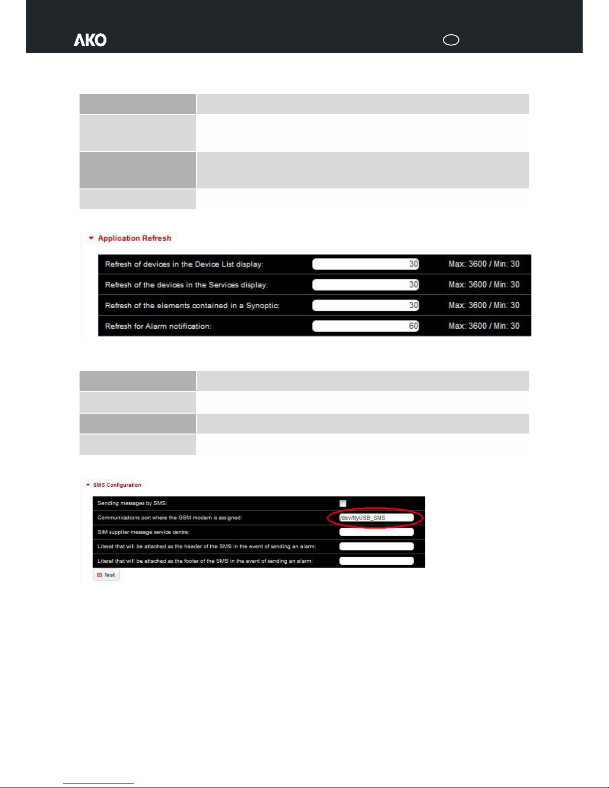
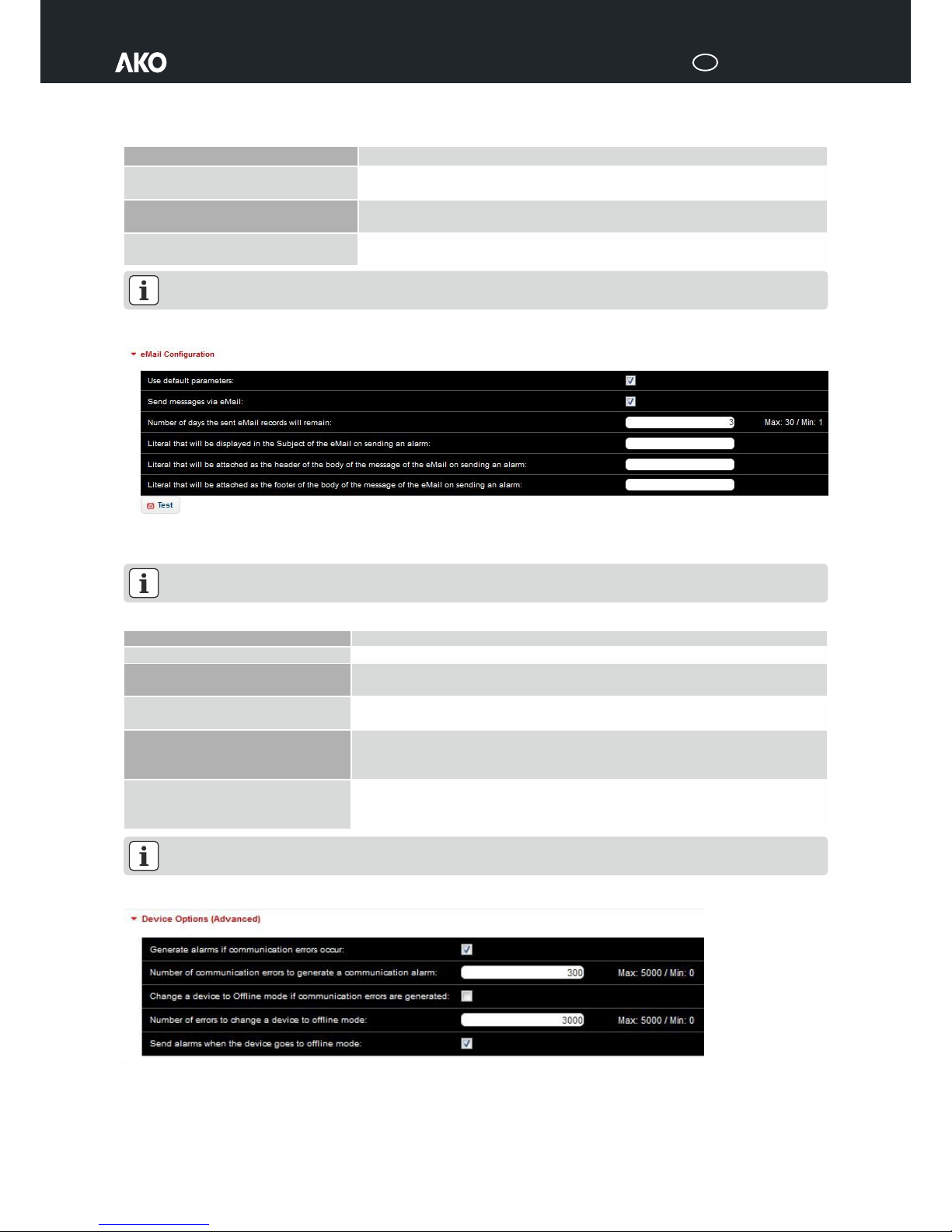
General Configuration...............................................................................................................................................5
Users and Groups ...................................................................................................................................................10
LAN Configuration..................................................................................................................................................11
Datetime and Timezone...........................................................................................................................................11
Search for Devices...................................................................................................................................................11
Devices Registered..................................................................................................................................................12
Task Planner ...........................................................................................................................................................13
Alerts and Alarms ...................................................................................................................................................15
Mobility Configuration ............................................................................................................................................15
Backups..................................................................................................................................................................16
Modbus Testing ......................................................................................................................................................16
Remote Access (via TeamViewer).............................................................................................................................16
Alarm ............................................................................................................................................................................17
Facilities.........................................................................................................................................................................17
Services..........................................................................................................................................................................18
Devices ..........................................................................................................................................................................19
Device detail display ................................................................................................................................................20
Graphs...........................................................................................................................................................................22
Reports..........................................................................................................................................................................23
Other Reports .........................................................................................................................................................23
Sample Reports.......................................................................................................................................................23
Advanced Report.....................................................................................................................................................25
Synoptics .......................................................................................................................................................................25
Synoptics Design.....................................................................................................................................................26
Docs management..........................................................................................................................................................27
New Document.......................................................................................................................................................27
Appendix I: Akonet connection scenarios..........................................................................................................................28
No Ethernet-TCP/IP connection, only WiFi .................................................................................................................28
Ethernet-TCP/IP connection, without Internet access .................................................................................................29
Ethernet-TCP/IP connection, with Internet access ......................................................................................................30

5010H002 Ed.06
GB
3
Introduction
Welcome to AKONet, AKO's new monitoring, supervision and control software.
AKONet has been designed since its conception to be accessible and very
easy to use, but at the same time very efficient and capable of scaling up to
meet the demands of even the largest projects.
The objective of this guide is to introduce the software and its architecture,
allowing users to start using it as quickly as possible, and subsequently to
provide all the necessary resources to get the most out of it.
For any questions related to the installation and/or configuration of the
devices, please refer to the Quick guide 5012H001 and note 5012H011, or
the Quick guide 5014H001 and note 5014H011.
Quick guide
Starting the Application
To access AKONet you need to open a browser (we recommend Google
Chrome) and enter one of the following IPs: the one of the WiFi if you are
accessing via WiFi (10.0.0.1); the one you have configured as the device IP if
you are accessing through intranet (or without IP and with the name of the
device akonet.xxxxxxx.xx); or localhost if you are accessing via TeamViewer.
For more information about the different ways to access AKONet, please
refer to Appendix I: Akonet connection scenarios (Page 28).
By default, the application responds on port 80 (http).
The default admin user is superuser and the password is superuser. After
entering the user and password, click the Login button and AKONet 's main
window will appear.
Application Work Area
Whenever you wish to save any changes made, remember to always press the Accept button afterwards.
The application work area is divided into three parts:
General menu area
This area contains the most important menu options of the application.
The options are displayed or are hidden according to the permissions of the group the user is assigned to. For more information, see section
Users and Groups (Page 10) of this manual.

5010H002 Ed.06
GB
4
The menu points are:
Administration
In this menu you will find all the application's setup options, and here you can maintain Users and Groups, Alerts and Alarms, etc.
Alarm
This option will open the list of existing alarms, and you can confirm them, print them or change the filters to see the alarm log.
Facilities
This option will open a list of all facilities, whether they are Serial or Ethernet, positioned on a map. Clicking on them will allow you to access
the services of each one.
To enable this option, check the Geopositioning enabled check box in Administration->General Configuration->General Parameters-
>System Options (Advanced). There has to be at least one facility.
Services
This option displays all registered devices, grouped (using tabs) according to the services to which they belong. This should be the default view
of the application.
A service is a functional group of devices, for example, positive or negative cold rooms, and they are created by the client in order to identify the
device more easily.
Devices
This menu also shows the devices, but in a list format, displaying the most important variables of each one.
In this section you will see that the devices are grouped according to its model:
ŸAKO Controls, where you will find all the AKO control devices.
ŸCAMRegis; it will display all the temperature data logger devices.
ŸAKODUO; the DUO family devices will be displayed.
ŸCAMAlarms; all the alarms will be listed.
ŸAKOGAS; all the gas leak detection devices will be listed.
Graphs
This option allows you to enter the graph generation Wizard.
Reports
You can use this option to obtain all the reports (lists) of the samples of your devices.
Synoptics
This option allows you to access the graphical representation module of the facilities.
Docs Management
This last option gives you access to where the generated reports are stored.
This manual will provide more information about each of these options below.
Apart from these options, the top menu also has four other icons for the purpose of a series of basic tasks:
This icon will automatically take you to the application home screen.
The default view is the Services screen. This option displays all registered devices, grouped (using tabs) according to the services to which they
belong.
When you click this button, the system will save the current screen as the new application home screen for the current user.
This takes you to the application's help section.
Closes the session and returns to the login window.
Work area
This is the central application area, and it will be where all the application's screens are displayed.
Bottom information bar
Occurring alarm events are displayed in this area, as well as the date, the time and the current software version.

5010H002 Ed.06
GB
5
Administration menu
Clicking on the administration icon will take you to the application’s administration menu.
You will see the following Administration screen.
General Configuration
This icon will take you to the main parameters of the application.
Facilities
The facilities can be of two types: Serial (USB AKO-80039) or Ethernet (IP AKO-80080), according to the type of MODBUS connection that has been selected.
There can only be one Serial facility and it will always point to the following port: /dev/ttyUSB_485. It is created by default and the Name is the only
thing that needs to be changed.
However, one can create as many Ethernet facilities as required (up to 12). They are used in cases where there are multiple devices located on various
different floors, when there are more than 25 devices, etc. Each one of these facilities should
point to the IP address that was previously assigned to the AKO-80080 converter.
Remember that in order for the facilities to be used in the application, their Status must be set
to Active.
Services
Another important point to bear in mind in the initial configuration is the configuration of the
services. A service is a logical way of grouping your facility’s devices. You can create as many as
necessary.
This step is not compulsory, since AKONet creates the Default service by default.
When a new service is added, it will be visible for all User Groups, but you can assign service
visibility to specific Groups when the service is added or
modified.
In this example, only Viewers, Administrators and
Operators would be able to see the devices that belong
to the Frozen Cabinets service. None of the other
groups would be able to view the service or the devices
in it. For more information about the different types of
users, see section Users and Groups (Page 10) of this
manual.
In order to sort the services, they can be dragged and
dropped.
More information about the services is provided in
section Services (Page 18) of this manual.
Once the service is created, the relevant devices will
need to be assigned to it. For more information on how
to assign devices to services, please refer to section
Devices Registered (Page 12) of this guide.

5010H002 Ed.06
GB
6
General Parameters
AKONet's operation is governed by a series of general system variables. These can be
modified by any administrator user. From here, you can access the configuration of all
system variables, grouped as follows: Visual Configuration, Data Recording, Application
Refresh, Sending of alarms by SMS, Sending of alarms by eMail, Device and System.
Visual Configuration Options
This section includes the variables that affect the display of data relative to the user location, such as the date format, the first day of the week, etc.
Data Recording Configuration
The variables in this section determine the way in which AKONet is going to obtain log records.
Events refer to alarms. You will find more information about them below.
Long date format
This allows establishing the format in which the dates will be displayed (date and time).
Short date format
This allows establishing the format in which the dates will be displayed (only date).
First day to display in calendars
It establishes the first day of the week.
Server message language
It establishes the language in which the reports of the planned tasks will be generated, regardless of the
user language.
Application style (requires
rebooting)
AKONet allows changing the general appearance of the application based on some pre-set styles.
You need to reboot AKONet for the change to take effect.
Graph background colour
(requires rebooting)
AKONet allows changing the background colour of graphs between four different options.
You need to reboot AKONet for the change to take effect.

5010H002 Ed.06
GB
7
Application Refresh
The variables in this section are used to mark the number of seconds it takes the application to automatically update device data in the following screens:
Alarm, Services, Devices and Synoptics.
SMS Configuration
Here, you can configure a series of necessary variables for the correct functioning of SMS notifications.
See also sections Mobility configuration (Page 15) and Alarm (Page 17) of this manual.
If you have purchased the AKO-52043 GSM Modem, AKONet will be able send alarm notifications via SMS, but in order to do so, you should tick the
Sending messages by SMS box, as well as enter /dev/ttyUSB_SMS as Communications port. The other fields have to be left unfilled. The PIN
code of the Modem SIM card must be removed. For any questions related to the SMS Configuration, consult the AKO-52043 manual.
Click Accept to confirm the changes made and hit the Test button to check the sending of the SMS notifications.
Sample generation mode
This parameter allows establishing how the log will be obtained: each device can be made to record samples according to
different intervals, or all devices can log samples at the same time.
Interval in minutes between
samples
If the previous parameter is set to General interval, this interval can be established here.
Be careful, entering very small values would not be advisable (one minute for example). This will affect the
performance of the application. Intervals of 15 minutes are recommended.
Number of variation units required
for logging of new samples
In case of a General interval, this parameter will allow you to obtain extra samples if a device reaches a certain number
of variation units.
For example, all devices take samples every 15 minutes, but you have indicated that extra samples should be logged if
they vary in over one degree. If a device goes from 0 °C to 1 °C, this sample will be logged.
Number of months for sample
storage
This parameter refers to the number of months samples will be stored in the database. Adapt according to your needs, up until
a maximum of 120 months (or 10 years). Storage of 36 months is recommended.
Refresh seconds of devices in the
Device List display
This allows establishing the number of seconds it will take for data in the Device List screen to be updated.
Be careful, setting very low values will have a negative impact on performance.
Refresh seconds of devices in the
Services display
This allows establishing the number of seconds it will take for data in the Services screen to be updated.
Be careful, setting very low values will have a negative impact on performance.
Refresh seconds of elements
contained in a Synoptic
This allows establishing the number of seconds it will take for data in the Synoptics screen to be updated.
Be careful, setting very low values will have a negative impact on performance.
Refresh seconds for Alarm
notification
This allows establishing the number of seconds it will take for Alarm notification data to be updated.
Be careful, setting very low values will have a negative impact on performance.

5010H002 Ed.06
GB
8
After confirming the parameters, the server will need to be rebooted in order for the changes to take effect.
eMail Configuration
Here, you can configure a series of necessary variables for the correct functioning of eMail notifications. See also sections Mobility Configuration (Page
15) and Alarm (Page 17) of this manual.
In order for AKONet to be able to send eMails, the computer on which the application is installed needs to have internet access.
Click Accept to confirm the changes made and hit the Test button to check the sending of the eMail notifications.
After confirming the parameters, the server will need to be rebooted in order for the changes to take effect. For more information, see
Appendix I: Akonet connection scenarios (Page 28).
Device Options (Advanced)
These advanced options control a series of parameters related to the application behaviour in case of communication, or modbus, errors between the
devices and AKONet. See also section Alarm (Page 17) of this manual.
Sending of SMS messages
This box should be ticked for AKONet to send alarms via SMS.
Communications port the GSM Modem is
assigned to
If the AKO-52043 GSM Modem is connected through USB, AKONet will recognise it automatically and will
assign it to this field.
Literal that will be attached as the header of
the SMS in the event of sending an alarm
This allows for the adding of a default SMS header text.
Literal that will be attached as the footer of
the SMS in the event of sending an alarm
This allows for the adding of a default SMS footer text.
Use default parameters
This box should be ticked for the service to work correctly.
Sending messages via eMail
This box should be ticked for the service to work correctly.
Number of days failed delivery eMails will
be kept
If eMails fail to be delivered, the system will keep them and will reattempt delivery for a predefined number of
days.
Literal that will be displayed in the subject
of the eMail on sending an alarm
This allows for the adding of a default eMail subject text.
Literal that will be attached as the header of
the body of the message of the eMail on
sending an alarm
This allows for the adding of a default eMail header text.
Literal that will be attached as the footer of
the body of the message of the eMail on
sending an alarm
This allows for the adding of a default eMail footer text.

5010H002 Ed.06
GB
9
System Options (Advanced)
This last group contains parameters for the configuration of a series of general features related to application performance.
Document Folders
The document management module allows for the storage of all your facility related documentation within AKONet, for example, sample reports,
graphs, etc.
From here, you can access the configuration of your document folders. They can be organised as desired. Just give them a Name and a Description. The
URL refers to the storage path of the documents, that is, the folder on the Linux server where the documents will be stored.
This step is not compulsory, since AKONet creates the Default folder by default.
More information about document management is provided in section Docs Management (Page 28) of this manual.
Generate alarms if communication errors
occur
This feature allows enabling or disabling alarm generation in the case of communication errors with any given
device.
Number of communication errors to
generate a communication alarm
If the previous parameter has been enabled, this parameter indicates how many errors should occur before
alarm generation is triggered.
Change a device to Offline mode if
communication errors are generated
This check box allows for the removal of a device from the network in case of communication errors.
Number of errors to change the device to
Offline mode
If the previous parameter has been enabled, this parameter indicates how many errors should occur for any
given device to be taken Offline.
Send alarms when the device goes to Offline
mode
If this feature is checked, the system will send an eMail alert after taking the device Offline.
Sending messages when the alarms are
disabled
When activated, an alarm generated by a device which was subsequently solved (for example, a maximum
alarm), will trigger the system to send a notification with the information that the alarm does not exist anymore.
AKO Live Update Enabled
AKONet is equipped with an automatic update functionality in order to guarantee your version of AKO is the
most recent one at all times.
When activated, the system will check for new updates every 8 hours.
In order to download and install the updates correctly, the computer on which the application is installed
needs to have internet access. Remember that while an update is being executed, the system will
be temporarily down and users will not be able to access it until the process is finished.

5010H002 Ed.06
GB
10
Users and Groups
This icon will take you to the configuration screen of the application users and groups.
In order to create the users and groups of users needed for the correct functioning of the application, the goal is to register those users who:
ŸAre going to access the application.
ŸWill need to be notified via SMS or via eMail in case of any system alarms.
ŸWill need to receive reports via eMail.
Before creating the users, it is important to set up groups of users and assign permissions to them; in other words, it is important to prevent users from
having unrestricted access to the application.
Maintenance of Groups
To create the user groups, go to the Groups tab.
Careful, the Administrators group should not be deleted yet, as doing so would remove the superuser.
A series of AKONet functions can be assigned to each group of users:
ŸAdministration: this option allows or denies access to the administration menu, and enables or disables the synoptics create and edit
options, the document maintenance option in the document management module, and, in general, any option for the purpose of deleting
general features.
ŸDevice Configuration: this option provides access to the modification and configuration of device variables.
ŸSet Point: this option provides access to the modification of service temperature Set Points.
ŸAccess to Graphs: Access to the graph generation function can be allowed or denied using this option.
ŸAccess to Synoptics: Allows or denies access to the synoptics module.
ŸAccess to Reports: This option controls which users should get access to the reports module.
ŸAccess to Doc. Man.: This option controls which users should get access to the document management module.
Three groups are created by default: Administrators, Operators and Viewers. The creation of further groups is not generally required, although they can
of course be created as desired.
ŸAdministrators, with unrestricted access to the application.
ŸOperators, with access to everything except for the Administration option; all users who need to modify system variables, such as Set Points,
should be included in this group.
ŸViewers, with no access to Administration and Device Configuration; all users whose daily job consists exclusively of monitoring tasks, and
who in no case should have access to the modification of system variables, should be included in this group.
Maintenance of Users
After registering all required groups, it is time to create the users who are going to use the system. To do so, go to the Users tab.
Click New to add new users. This button will take you to a pop-up window for the registration of said users. Here, you should include all the user data.
You should pay special attention to the group you assign the user to.
Make sure you fill in the eMail and Mobile Telephone fields correctly so that the user may receive alarm notifications via eMail and/or SMS.
For more information, see section Mobility Configuration (Page 15) of this manual.
To configure which users should be allowed to view facilities, click on the Permissions button and select the relevant facilities from the list of those
available.

5010H002 Ed.06
GB
11
LAN Configuration
This icon will take you to the configuration screen of the LAN configuration.
You will see the following LAN Configuration screen.
The IP must be static, that is, fixed. It does not change. To do this, the property must provide the following information: AKONet IP, Network Mask,
Gateway, DNS1 and DNS2. This data should be provided by the network administrators. Do not change any values unless requested by a network
administrator. For more information, see APPENDIX I: AKONET CONNECTION SCENARIOS.
In case of internet access problems (Internet Access: Error), in case of eMail delivery failures for example, contact the network administrators.
Datetime and Timezone
This icon will take you to the datetime and timezone configuration screen.
It allows you to configure the date and time options of the application; which is particularly important for the data log to be consistent.
These parameters are configured during the installation, but they can be changed as needed.
Search for Devices
This icon will take you to the screen for you to search for devices registered in the network.
You will see the following Search for Devices screen.
Here, you can see the facilities as well as the MODBUS addresses from Start to End. This is where AKONet is going to search for AKO devices registered in
the network. You can apply filters to limit the search results.
When clicking on Search for Devices and after waiting a few moments, a list with all devices found is shown. The time is takes to complete the search
depends on the range of addresses to search, the number of devices found, etc. After the search, save any changes made to the list of devices. They will
automatically appear among the Devices Registered (see next section). Renaming them to make them more easily identifiable is recommended.
If the devices found are already in the Devices Registered list, it will not be possible, nor necessary, to save the list.

5010H002 Ed.06
GB
12
For more information related to the configuration of the devices, refer also to the Quick guide 5012H001 and note 5012H011, or the Quick guide
5014H001 and note 5014H011.
Devices Registered
This icon will take you to the configuration screen of the
devices registered in the application.
Apart from the automatic search for devices, you also have the option to
manually register devices connected to the modbus network, using the
AKO-80039 converter.
To do so, hit the New Device button.
The parameters are the following:
ŸFacility: If you have purchased AKONet, you can select the
facility the device is assigned to from the dropdown menu. If
not, stick to the default facility.
ŸService: This will display all the previously registered services.
Pay attention to the service you assign the device to.
ŸName: Include a text that identifies the device, for example,
Frozen Food, Vegetables, etc.
ŸBus address: You should indicate the bus address of the device you are registering. Remember bus addresses have to be unique within a single
facility.
ŸModel: Assign the exact device model.
ŸSerial Number: Enter the device serial number. This is not compulsory.
ŸGenerate DataLog: If you select Yes, the system will obtain samples and log them to be able to generate graphs and lists later on. In case you
only want to monitor and are not bothered about logs, select No.
ŸStatus: For AKONet to be able to communicate with the device, it needs to be set to Active. If it is Inactive, it will be saved in the database, but no
communication attempts will be made.
ŸLocation: You can assign a more specific location for the purposes of control.
Once a device is registered, it will appear in the list of registered devices.
If it is a device with memory, CAMRegis dataloggers for example, the logs will start downloading automatically.
From then on, the registered device will appear in AKONet.
For more information about devices, see section Devices (Page 19) of this manual.

5010H002 Ed.06
GB
13
Task Planner
This icon will take you to the task planner configuration screen.
AKONet’s Task Planner functionality allows you to execute scheduled tasks according to a calendar. There are three types of tasks that can be scheduled:
automatic report generation, device feature modification and backups.
Automatic Report Generation
Automatic report generation serves to schedule tasks for the systematic generation of reports based on parameter data from one or several specific
devices. The user thus remains exempt from having to obtain these logs manually.
For example, a task can be scheduled so that at the beginning of each month, samples from a given device are sent by mail and saved in the document
management module.
In order to do so, the scheduled task creation window contains the following features:
ŸName: Free text for the purposes of identifying the task later on.
ŸDescription: Free text for the purposes of identifying the task later on.
ŸColour: Colour for the purposes of identifying the task later on.
ŸStarts on: Sets the date and time for the first execution of the task.
ŸType: For reports, select Report.
ŸDocument Type: Format in which the report will be saved.
ŸSelect the destination of the report: Here, you can decide how to send on the report, and it can be sent to:
Document Management, by selecting the destination folder. For details on the configuration of Folders, see Document Folders.
eMail address, by filling out one or several addresses, separated by commas.
ŸIt is repeated: Select how often the task will be repeated. The possible options are: every day, every week and every month.
ŸEnds on: Indicate when the task should end, by choosing a specific date.
After registering the report, a window will be displayed for the selection of parameters to be included in the report.
You can select any registered device; selecting a specific one will automatically load all properties which generate the logs for the selected device.

5010H002 Ed.06
GB
14
Device Feature Modification
Device feature modification serves to schedule tasks which involve communication with devices, such as the systematic modification of set points.
In order to do so, the scheduled task creation window contains the following features:
ŸName: Free text for the purposes of identifying the task later on.
ŸDescription: Free text for the purposes of identifying the task later on.
ŸColour: Colour for the purposes of identifying the task later on.
ŸStarts on: Sets the date and time for the first execution of the task.
ŸType: For the modification of device features, select Device Control.
ŸIt is repeated: Select how often the task will be repeated. The possible options are: every day, every week and every month.
ŸEnds on: Indicate when the task should end, by choosing a specific date.
After registering the report, a window will be displayed for the selection of device parameters to be modified and for the setting of target values after task
execution.
Backups
This functionality serves to schedule tasks for the systematic generation of backups. By default, AKONet performs weekly backups.
In order to do so, the scheduled task creation window contains the following features:
ŸName: Free text for the purposes of identifying the task later on.
ŸDescription: Free text for the purposes of identifying the task
later on.
ŸColour: Colour for the purposes of identifying the task later on.
ŸStarts on: Sets the date and time for the first execution of the task.
ŸType: For backups, select Backups.
ŸSelect the destination of the repXHMGoƒ‰‡?e•’o†‡˜™?c•…›“‡”š?™‡‡?e•’†‡˜™K?•ˆ?…•”ˆ‹‰›˜ƒš‹•”?šŠ‡?r•”?†‡šƒ‹’™?e•˜?ˆ•t’†‡˜M?†‡™š‹”ƒš‹•”?šŠ‡?r‡’‡…š?e•:’†‡˜Y?lƒ”ƒ‰‡“‡”š?c•…›“‡”š??
ŸIt is repeated: Select how often the task will be repeated. The
possible options are: every day, every week and every month.
ŸEnds on: Indicate when the task should end, by choosing a specific
date.

5010H002 Ed.06
GB
15
Alerts and Alarms
This icon will take you to the alerts and alarms sending logs.
This is where the successfully sent alarms are stored. See also section 4 Alarm of this manual.
Alarms can be resent by pressing the Resend button.
Mobility Configuration
This icon will take you to the mobile, eMail and SMS access configuration screen.
The sending of messages by SMS or eMail can be enabled or disabled for every AKONet user, as well their access from mobile devices. By default, a newly
registered user is given permission to be notified by SMS as well as by eMail and is able to access the application using mobile devices.
Use the Yes and No buttons to enable or disable access to each of the abovementioned functionalities.
In order for users to be able to receive SMS messages and/or eMails correctly, 3 conditions must be fulfilled:
1. The user must belong to a group with access to the relevant information
2. The user Mobile Telephone and/or eMail fields must be filled out correctly
3. The Send SMS and/or Send EMails boxes must be checked.

5010H002 Ed.06
GB
16
Backups
This icon will take you to the system backup management screen.
AKONet provides tools for the generation and restoration of backups.
This option is only accessible for users with administration rights and is not available in demo mode.
Generate Backup
From the Generate Backup tab, you can generate new backups. By pressing
the Execute button, the system will back itself up (this process might take
some time, depending on the volume of information to be backed up) and
once this is finished, you will see this icon:
Click on it to download the file onto your computer and
save it for future reference.
Restore Backup
To restore a backup file, follow the following steps:
1.- Copy the akonet-backup.bak backup file to
the /home/debian/akonet folder
2.- Open a terminal and execute:
cd /home/debian/akonet
sudo ./restore.sh
Modbus Testing
This icon will take you to the testing of the devices on the modbus
line.
To find out if whether the connection between AKONet and the various
registered devices is working properly, the application will launch a
MODBUS request to all the devices connected to the network. In response,
said devices will display their MODBUS address and show a green and red
icon, equivalent to RX/TX.
This screen contains the filters by which AKONet will launch the request.
Remote Access (via TeamViewer)
This icon will take you to TeamViewer.
TeamViewer is an external tool for accessing the remote Linux desktop.
By clicking on it, you activate it (1). You can assign your own Password (2) and the red icon contains the TeamViewer ID with which you must connect (3).
With this information (ID and Password) you will be able to access the remote desktop through TeamViewer.
For more information, see Appendix i: akonet connection scenarios (Page 28).
1.- Activate TeamViewer 2.- Assign Password of your choice 3.- Obtain TeamViewer ID

5010H002 Ed.06
GB
17
Alarm
Clicking on the alarm icon will take you to the application’s alarm menu.
You will see the following Alarm screen.
An important element of AKONet is the possibility to emit Alarms via eMail and SMS. For details on the configuration of Alarms, see General Parameters
(Page 6).
AKONet is designed to be able to satisfactorily manage any exception which might arise in a facility and to do so it detects device alarms and provides
different ways of notifying users of these exceptions:
ŸBottom alarm notification bar: The software provides a bottom bar with alarm information in real time.
This control is updated automatically, according to configurable intervals.
By clicking on an alarm in the bottom bar, you open a pop-up window with the alarm details. You will be able to:
Access the device by pressing the See Device button.
Confirm the Alarm, this will stop the alarm from being displayed in alert format to all users.
ŸPop-up messages: When an alarm goes off, AKONet displays it to all users by means of a pop-up message.
By clicking the AKONet message, more information will be shown, together with the Confirm and See Device
options.
The generated alarms will be sent via:
ŸeMail.
ŸSMS (if the software is purchased together with the GSM Modem).
Facilities
Clicking on the facilities icon will take you to the application’s facilities menu.
This option will open a list of all facilities, whether they are Serial or Ethernet, positioned on a map. Clicking on them will allow you to access the services
of each one.
To enable this option, check the Geopositioning enabled box in Administration->General Configuration->General Parameters->System Options
(Advanced). There has to be at least one facility.

5010H002 Ed.06
GB
18
Services
Clicking on the services icon will take you to the application’s services menu.
You will see the Services screen. The services menu option allows you to visualise graphically the state of a facility. This screen is divided into tabs, one for
each service you have registered and a further two tabs which display all devices and those that are Offline. For details on the configuration of Services,
see Services (Page 18).
In this example, two services have been registered in AKONet: Frozen Cabinets and Positive Cabinets; two further tabs, All and Devices Offline, are
shown.
When you click on a service, the application will display the devices that belong to that service.
This window is automatically updated after a certain period of time. You can define this yourself in the general parameters (Administration->General
Configuration->General Parameters->Application Refresh->Refresh of the devices in the Services display). By default, this parameter is set at 30
seconds.
You will be able to follow up on changes in the current state of the facility in this window.
Devices are shown in the following format:
Devices, such as CAMRegis, with a higher number of probes and no relay statuses, are shown in the following way:
By clicking on a device, further device details will be shown. In case of a device alarm, the device background will be displayed in red. In case of device
communication errors, the device background will be displayed in orange.
Device name
Service (and facility)
Probe 1 value
Probe 2 value
Relay statuses
Device image
Set Point value

5010H002 Ed.06
GB
19
Devices
Clicking on the devices icon will take you to the application’s devices menu.
You will see the following Devices screen.
The Device List displays the devices in a list format. This screen is divided in tabs, one for each device type. There are five types: AKO Controls, CAMRegis,
AKODUO, CAMAlarms and AKOGAS. For more information on the configuration of Devices, see Devices Registered (Page 12).
This division is pertinent because of the different display formats of each device type, due to the fact that the important data is different for each group.
Moreover, there are two view types: one Normal, and the other Technical. Therefore:
AKO Controls displays:
ŸAlarm icon, which indicates whether there are device alarms, and
how many.
ŸFacility to which it belongs.
ŸService to which it belongs.
ŸDevice name.
ŸIn technical view, bus address.
ŸDevice model.
ŸSet Point value.
ŸCOOL relay status.
ŸIn technical view, DEFROST relay status.
ŸIn technical view, FAN relay status.
ŸProbe 1 value.
ŸIn technical view, Probe 2 value.
ŸIn technical view, Probe 3 value.
AKOGAS displays:
ŸAlarm icon, which indicates whether there are device alarms, and
how many.
ŸFacility to which it belongs.
ŸService to which it belongs.
ŸDevice name.
ŸIn technical view, bus address.
ŸDevice model.
ŸGas concentration.
ŸInternal temperature.
ŸRemote mute.
ŸRemote set hold.
ŸHit the See Device button in order to access further device details
for each of the five groups of devices.
CAMRegis displays:
ŸAlarm icon, which indicates whether there are device alarms, and
how many.
ŸFacility to which it belongs.
ŸService to which it belongs.
ŸDevice name.
ŸIn technical view, bus address.
ŸDevice model.
ŸProbe values, up to 10 (depending on the specific model, more or
fewer probes will be displayed).
AKODUO displays:
ŸAlarm icon, which indicates whether there are device alarms, and
how many.
ŸFacility to which it belongs.
ŸService to which it belongs.
ŸDevice name.
ŸIn technical view, bus address.
ŸDevice model.
ŸProbe values, up to 5 (depending on the specific model, more or
fewer probes will be displayed).
CAMAlarms displays:
ŸAlarm icon, which indicates whether there are device alarms, and
how many.
ŸFacility to which it belongs.
ŸService to which it belongs.
ŸDevice name.
ŸIn technical view, bus address.
ŸDevice model.
ŸInput, up to 4.
Hit the See Device button in order to access further device details for each of the five groups of devices.

5010H002 Ed.06
GB
20
Device detail display
Device details are displayed in tabs where you can easily access all relevant data, such as alarms, temperatures, relay statuses and graphs.
On the left, you can see the Current Values of the probes and all digital input.
Likewise, general device data is displayed here: the Facility to which the device belongs, the Service, the Name, the Address, the Model and the Serial
Number. The Status indicates whether the device is Active or not, that is, whether it is currently communicating at the MODBUS level or not.
On the right, you can see the Statuses of the device relays and the Remote control's virtual keypad. It also indicates whether or not the device has any
Alarms; and if there are, it shows how many. In case of multiple Alarms, only the first one is displayed.
For each type of device, there are several buttons which carry out different actions. All devices have Return, Update, Change Set Point (provided that
the selected device has SP properties) and Probe Configuration buttons (although the labels of the buttons may vary). But other buttons may be
available.
The bottom half of the screen displays device data as graphs. By default, data from the last three days is shown, but you can select other relevant data by
using the filters.
The other tabs provide access to the most important tasks. These are:
ŸDevice configuration (download confirmation is required).
Table of contents
Other AKO Server manuals
Popular Server manuals by other brands

Microframe Corporation
Microframe Corporation EzWait 5330 Series installation guide

Cisco
Cisco CSACS-1121-K9 reference guide

Fujitsu
Fujitsu PRIMEQUEST 2000 Series installation manual

CasaTunes
CasaTunes CT-1 quick start guide

Atop
Atop ABLELink SE5001 quick start guide

Supero
Supero SUPERO SuperServer 5037MC-H8TRF user manual