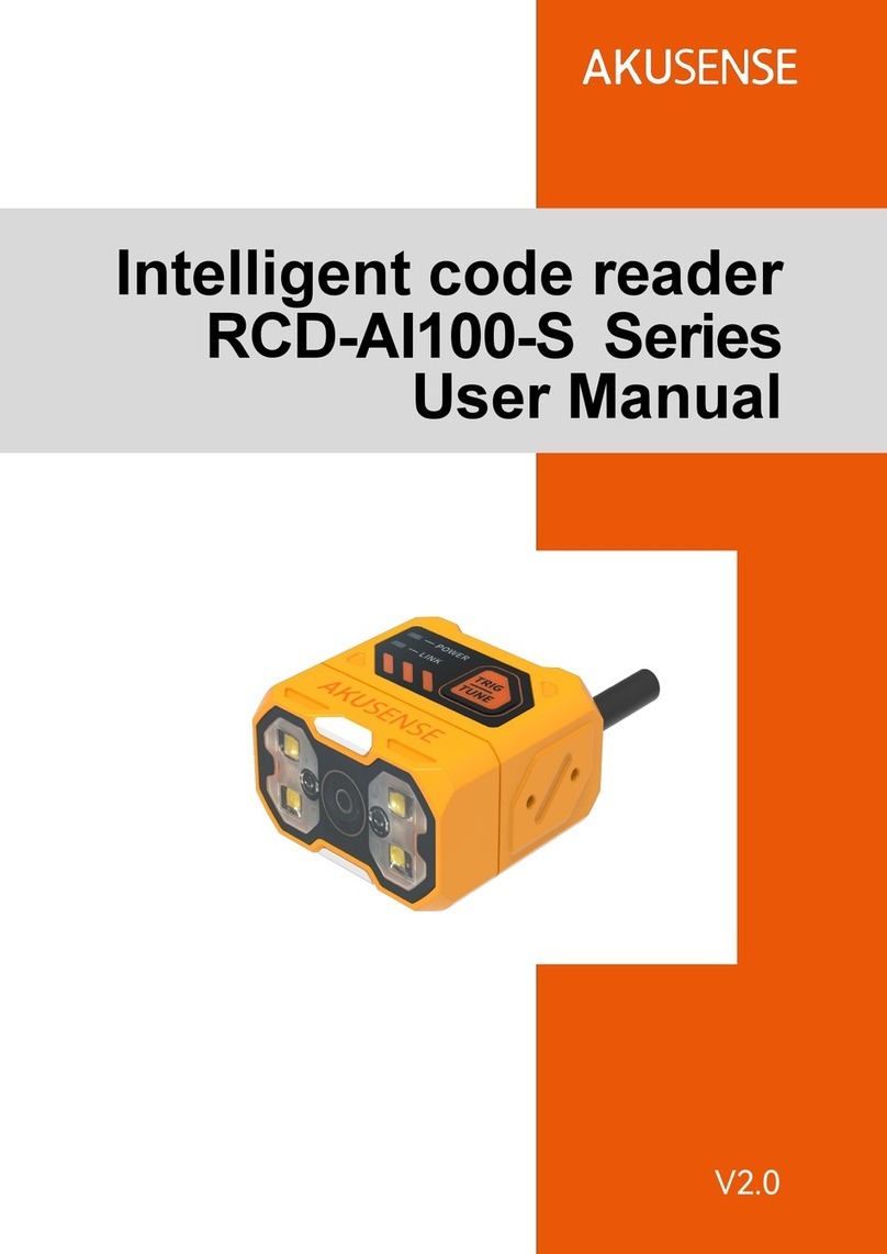
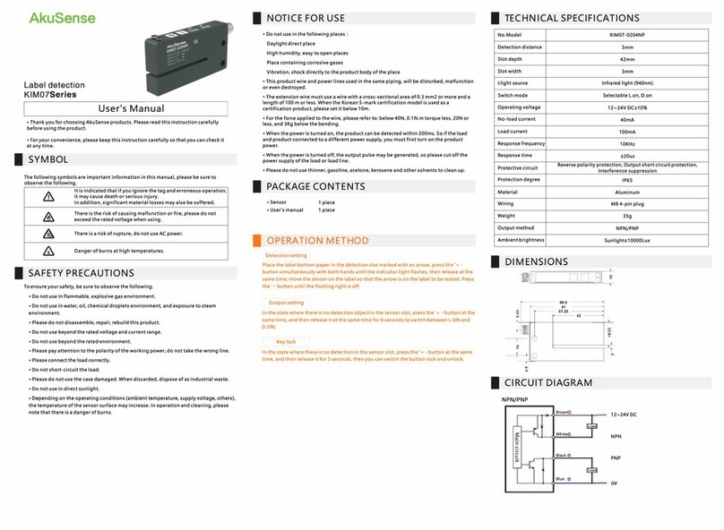
AkuSense AS-21C User manual

AS-21C User Manual
V.261119

I
AS-21C Users Manual
Contents
Contents
1. Document Description.................................................................................................................1
1.1 Reminder.............................................................................................................................1
1.2 Content Description...........................................................................................................1
1.3 Pattern symbol description...............................................................................................2
1.4 Extended reading...............................................................................................................4
2. Basic operation and precautions...............................................................................................5
2.1 Correct method of use...................................................................................................... 5
2.2 Incorrect usage warning................................................................................................... 5
2.3 Networking instructions.................................................................................................... 5
2.4 Disclaimer of equipment damage................................................................................... 5
2.5 Laser radiation instructions..............................................................................................6
2.6 Power supply and quick start and stop..........................................................................6
2.7 Maintain...............................................................................................................................7
3. Product description......................................................................................................................9
3.1 Deliveries............................................................................................................................ 9
Deliverables.......................................................................................................................................9
3.2 Product characteristics................................................................................................... 10
3.3 Operational principle....................................................................................................... 11
3.3.1 Distance measurement....................................................................................... 11
3.3.2 Two-dimensional scanning................................................................................. 12
3.3.3 Scene measurement and regional monitoring................................................13
3.4 Device interface...............................................................................................................14
3.5 Equipment control and operating status display........................................................ 15
3.5.1 Equipment control method................................................................................. 15
3.5.2 Indicator light Indicator........................................................................................16
3.5.3 Front panel operation buttons............................................................................17
4. Applications.................................................................................................................................19
4.1 Technical Application.......................................................................................................19
4.1.1 Actual range.......................................................................................................... 19
4.1.2 The relationship between spot diameter and target size.............................. 20
4.1.3 Rain fog and dust penetration............................................................................20
4.1.4 Pseudo edge point...............................................................................................20
4.1.5 Mirror target...........................................................................................................21
4.1.6 Transparent medium........................................................................................... 22
4.1.7 Strong light interference......................................................................................23
4.2 Application System Development Overview...............................................................24
4.3 Network configuration and device detection...............................................................28
4.3.1 Device configuration information broadcast....................................................28

II
AS-21C Users Manual
Contents
4.4 Regional monitoring function and application development.................................... 29
4.4.1 Operating principle...............................................................................................29
4.4.2 Regional groups and monitoring regional groups.......................................... 30
4.4.3 Monitoring area group selection mode.............................................................33
4.4.4 Background self-learning and zone group background tailoring................. 33
4.4.5 Monitoring mode.................................................................................................. 35
4.4.6 Normal target self-learning and exclusion (customized function)................36
4.4.7 Forced control.......................................................................................................37
4.4.8 Monitor signal output........................................................................................... 38
4.5 I/O interface usage instructions and application development................................39
4.5.1 I/O input terminal function definition................................................................. 39
4.5.2 I/O output terminal function definition...............................................................41
4.5.3 I/O interface network message..........................................................................42
4.6 Device self-test and device ready signal.............................................................................43
4.6.1 Equipment self-test item............................................................................................. 43
4.6.2 Device ready signal..................................................................................................... 45
4.7 Intrinsically safe configuration.......................................................................................45
4.8 Power saving mode........................................................................................................ 46
4.9 Device control and function switch...............................................................................47
5. Device installation......................................................................................................................50
5.1 Installation preparation................................................................................................... 50
5.1.1 Basic requirements for installation....................................................................50
5.1.2 Mounting material................................................................................................ 50
5.1.3 Installation location selection............................................................................. 50
5.1.4 Special reminder.................................................................................................. 51
5.2 Mounting height and pitch angle...................................................................................51
5.2.1 Mounting height and effective working distance.............................................51
5.2.2 Multi-LiDAR Height and Angle Adjustment at the Same Time..................... 52
5.3 Adjust the scan range..................................................................................................... 54
6. Electrical Installation................................................................................................................. 57
6.1 Installation steps..............................................................................................................57
6.2 Installation preparation................................................................................................... 57
6.2.1 Power supply........................................................................................................ 57
6.2.2 Power supply requirements and temperature characteristics for automatic
heating............................................................................................................................. 58
6.2.3 Grounding requirements.....................................................................................59
6.2.4 Wire requirements................................................................................................59
6.2.5 Connect PC...........................................................................................................60
6.3 Device interface signal definition.................................................................................. 60

III
AS-21C Users Manual
Contents
6.3.1 Power interface signal definition....................................................................... 60
6.3.2 Network interface signal definition.................................................................... 61
6.3.3 I/O interface signal definition..............................................................................61
6.4 Interface cable wiring......................................................................................................62
6.5 I/O interface external reference circuit......................................................................63
7. Equipment configuration and commissioning test............................................................... 64
7.1 Configuration and Test Procedures..............................................................................64
7.2 Software and equipment preparation...........................................................................64
7.3 Basic test.......................................................................................................................... 65
7.4 Device Configuration...................................................................................................... 65
7.5 Try running the test steps...............................................................................................66
8. Equipment maintenance...........................................................................................................68
8.1 Operation and Maintenance.......................................................................................... 68
8.2 Replace equipment......................................................................................................... 68
9. Troubleshooting..........................................................................................................................69
10. Specifications........................................................................................................................... 70
10.1 Data sheet...................................................................................................................... 70
10.2 Measuring coordinate system/scan range/range.................................................... 74
10.3 Equipment outline drawings........................................................................................ 75
10.4 Accessories outline drawings......................................................................................76
11. Update....................................................................................................................................... 78
12. Appendix................................................................................................................................... 79
12.1 Illustration directory.......................................................................................................79
...................................................................................................................................................79
12.2 Table directory................................................................................................................80

AS-21C User Manual
Document Description
1
1. Document Description
1.1 Reminder
This manual provides methods and precautions for proper use of the AS-21C LiDAR
product. In order to use this product safely, users should also pay attention:
Obey the necessary safety production guidelines.
Follow the AS-21C workplace safety regulations and general safety regulations.
This manual is intended for electrical and electronics professionals.
Important note
Before operating the AS-21C, please read this manual
carefully to familiarize yourself with the features and
functions of the AS-21C.
This manual does not cover the use of other equipment and
equipment in the installation and use of the AS-21C. If you
need this information, please read the documentation for
such equipment.
1.2 Content Description
This manual is intended to provide technicians with information on the installation,
electrical connections, equipment configuration, and maintenance of the AS-21C. Please
read the sections of this manual in order. The contents of this manual (in order) include:
Basic operation and precautions
Product manual
Product application
Device installation
Electrical Installation
Device Configuration
Equipment maintenance
Troubleshooting
Specifications
Table 1.1 Product basic information
Working environment
Indoor / outdoor
Light source
Infrared laser (905nm)
Laser safety Class
Class 1 (GB 7247.1-2012, human eye safety)

AS-21C User Manual
Document Description
2
Scan angle range
300° (-60°~+240°)
Scanning frequency
25Hz(system default)/12.5Hz/6.25Hz
Scan angle resolution
0.5°(system default)/0.25°/0.125°
Measuring range
0.1m~20m
10% reflectance range
15m
Built-in application
Regional monitoring
Operating Voltage
10V~28V DC
Power consumption
5W(Measuring) ,3.6W@DC12V / 14.4W@DC24V
(Heating)
Shell Protection Class
IP65 (GB 4208-2008)
Weight
0.6Kg
Dimension(L╳W╳H)
83.5╳85╳104.9(mm)
Working temperature range
-25℃~+50℃
Storage temperature range
-30℃~+70℃
Ambient illumination range
≤70,000lux
Important note
For complete technical information, please read "10
Technical Specifications."
Please use the "LiDAR Diagnostic and Configuration
Software (FILPS)" to diagnose and configure the AS-21C.
How to use FILPS Please read the "LiDAR Diagnostic and
Configuration Software (FILPS) User's Manual".
1.3 Pattern symbol description
This manual uses the following pattern symbols to identify various important
precautions. Pay special attention when reading to avoid personal injury and equipment
damage.
Danger
Meaning:
Urgent and dangerous situations, if not guarded, may cause

AS-21C User Manual
Document Description
3
serious personal injury.
Caveat
Meaning:
Potentially dangerous situations, if not prevented, may cause
serious personal injury.
Cautious operation
Meaning:
Potentially dangerous situations, if not prevented, may result
in general personal injury.
Note
Meaning:
Potentially harmful conditions, if not prevented, may result in
equipment damage.
Important note
Meaning:
Helpful advice and tips for efficient and smooth use of the
device.
Main point
Meaning:
Information about important features of the device.
Explain
Meaning:
Technical background knowledge.
Instructions
Meaning:
Can provide more information related documents.
Related Reading
Meaning:
You need to use the FILPS software to complete the
equipment inspection and configuration.

AS-21C User Manual
Document Description
4
1.4 Extended reading
LiDAR Diagnostic and Configuration Software (FILPS): Windows installation
package and user manual for FILPS software.
LiDAR Application Development SDK: The basic C++ code library, Windows
dynamic library, demo program, and SDK user's manual for LiDAR application
development.

AS-21C User Manual
Basic operation and precaution
5
2. Basic operation and precautions
This chapter explains the basic operations and precautions involving personal safety
and equipment safety. Please read it carefully before using the AS-21C.
2.1 Correct method of use
AS-21C is an optical sensor for non-contact distance measurement. It can be used
alone, or it can be used on the network. It is mainly used to accurately measure the
surrounding environment and target contour, and it can also be used to build safety
precautions. Security protection, positioning and navigation applications.
The AS-21C can only be operated by professionals and used in a compliant
environment.
Important note
For the requirements of the AS-21C use environment,
please read "10.1 Data Book".
2.2 Incorrect usage warning
AS-21C can only be used for safety warning purposes and cannot physically
protect personal safety in hazardous environments.
AS-21C cannot be used in hazardous environments with explosive hazards.
The use of accessories not provided by AkuSense is at the user's own risk.
2.3 Networking instructions
The AS-21C uses standard TCP/IP technology for device networking. When actual
networking, you need to ensure the following prerequisites:
Users need to ensure the integrity and confidentiality of the data transmitted on
the network.
Necessary network security measures, such as network isolation, firewalls, and
anti-virus software, need to be planned and implemented by users themselves.
2.4 Disclaimer of equipment damage
AkuSense is not liable for equipment damage due to the following reasons:
Did not read the manual carefully.
Failure to properly use the equipment as required.
Operated by unqualified personnel.
Equipment dismantling without AkuSense approval.
Modification of equipment without AkuSense approval.

AS-21C User Manual
Basic operation and precaution
6
Technical transformation of the equipment.
Use self-made accessories.
2.5 Laser radiation instructions
AS-21C is measured with an infrared laser with a wavelength of 905 nm. The laser
beam is invisible to the naked eye.
Cautious operation
AS-21C meets the requirements of a class of laser safety
levels as specified in GB 7247.1-2012. Under normal
conditions of use, it is harmless to the human eye and the
skin. However, incorrect use of the AS-21C may bring
security risks. The matters are as follows:
Do not open the cover of the AS-21C. The powered
AS-21C will not stop laser firing when the cover is
opened.
Do not look directly into the laser output side of the
AS-21C for a long time, especially children, and
may cause blindness.
The laser output surface of AS-21C is an optical transmissive cover. The laser
warning mark is located on the top cover of the device, as shown in "Figure 2.1 Laser
output surface and laser warning sign".
Figure 2. 5Laser light output surface and laser warning sign
2.6 Power supply and quick start and stop
The AS-21C is powered by the DC002-type circular waterproof power socket in the
interface cable on the side of the device, as shown in the “Figure 2.2 Power Outlet”. the
power supply voltage is 10V~28V DC, and the power is in normal operation. The power

AS-21C User Manual
Basic operation and precaution
7
consumption is 5W and the maximum power consumption is 6W. When the internal
temperature is lower than 20 °C, the built-in heating module will start automatically, and
when it is higher than 30 °C, the heating will stop automatically. When the heating module
is started, the power consumption of the whole machine is 8.6W under the DC12V power
supply voltage, and the power consumption of the whole machine is 19.4W under the
DC24V power supply voltage.please provide power according to the above standards
when using.
Figure 2. 6 Power Outlet
Important note
Please read "10.1 Data Sheet" for the complete
requirements of AS-21C for power supply. The user shall
comply with local regulations and perform necessary
protection of the power supply cable of AS-21C to avoid short
circuit or overload of the power supply. In addition, an
emergency circuit breaker shall be installed on the power
supply cable for emergency use. Cut off the power supply
quickly.
Shutdown method: Turn off the power, or unplug the power cable from the power
outlet.
Power on method: Connect the power cable of the power outlet and turn on the
power switch.
The device configuration information of AS-21C is stored in a non-volatile storage
medium. Starting and stopping the device will not cause the loss of this information.
2.7 Maintain
Note
AS-21C must be maintained by AkuSense or AkuSense

AS-21C User Manual
Basic operation and precaution
8
designated agency staff. If repaired by other personnel, it
may cause damage to the equipment. Under such
circumstances, AkuSense will not be responsible for
subsequent maintenance.

AS-21C User Manual
Product description
9
3. Product description
3.1 Deliveries
AS-21C's product deliverables are shown in Table 3.1 product deliverables list.
Table 3. 1 Product deliverables list
Deliverables
qty
unit
Description
Certificate
1
piece
Warranty Card
1
piece
AS-21C
1
piece
LiDAR
AS-21C-AT
1
piece
Side-mounted/sitting composite
bracket
AS-21C-EC
1
piece
Power cable
1
piece
Standard RJ45 cable
AS-21C-WJ
1
piece
Network cable crystal head
waterproof jacket
Hexagonal M4*8 screws,
Gasket
1
set

AS-21C User Manual
Product description
10
3.2 Product characteristics
Table 3. 2 Product characteristics
Working
environment
Supply voltage range: 10V~28V DC.
Low power consumption: 5W.
Comprehensive outdoor work ability: anti-dirty, anti-sunlight, support
rain and fog penetration.
IP65 shell protection class;
-25°C~+50°C operating temperature range;
Distance
measurement
Pulsed flight time measurement technology system;
905nm infrared laser measurement, class 1 safety laser (GB
7247.1-2012, human eye safety);
Maximum range is 20 meters, and the 10% reflectance range is 10
meters;
Scanning
Mechanical scanning;
300° scan range, 0.5°(system default)/0.25°/0.125° scan angle
resolution;
25Hz(system default)/12.5Hz/6.25Hz scanning frequency;
Device
interface
Ethernet interface
Function: device configuration/measurement data output/ monitoring
signal output
I/O interface
Function: peripheral control, area monitoring function operation
control and monitoring signal output, Device ready indication
Built-in
application
Regional monitoring
Monitoring mode: point monitoring / target width monitoring / contour
monitoring;
16 modifiable preset area groups, support background contour
self-learning;
Up to 16 concurrent work area groups;
Can detect targets of any shape and support normal target
self-learning (customized function);
Disarming and forced alarms via I/O input terminals;
Monitor the signal through the I/O output terminal and Ethernet (TCP
message) output area;

AS-21C User Manual
Product description
11
Guided network cameras (IPC) for video location and tracking of
alarm locations and alarm targets via Ethernet and ONVIF protocols;
Support without PC configuration.
Availability
reliability
Anti-sunlight, anti-dirty, with rain and fog penetration ability
(optional);
Self-checking capability of equipment failure, including transparent
cover, dirty cover, temperature over-standard,Blocked by dense fog;
Output device self-test information through indicators and TCP
packets.
Figure 3.1 Measuring Coordinate System/Scan Range/Range
3.3 Operational principle
3.3.1 Distance measurement
The basic operating principle of the AS-21C distance measurement is based on
time-of-flight laser ranging. The AS-21C emits a laser pulse and measures the time it
takes for the pulse to return after being reflected by the surface of the measured target,
and then converts it into distance data, as shown in "Figure 3.2 operating principle of time
of flight measurement"
Figure 3.2 operating principle of time of flight measurement
AS-21C has multiple echo analysis capabilities. In the rain and fog and soot working
environment, atmospheric impurities will also reflect the distance measuring laser pulse,
forming a reflected echo pulse, and together with the reflected echo pulse of the

AS-21C User Manual
Product description
12
measured target, reach the photoelectric receiving system. The AS-21C analyzes all
received reflected echo pulses, rejects interfering pulses, and outputs true measured
target distance data, as shown in Figure 3.3 Reflected Echo Filter.
Figure 3. 1 Reflected Echo Filter
3.3.2 Two-dimensional scanning
AS-21C passes a 90degree deflection to the range laser pulse through a reflector
with an angle of 45 degrees with the original emitter path. The mirror is driven by the motor,
and the rotation axis is parallel to the original emitter path, so that the actual distance path
is distributed on the scanning plane perpendicular to the axis of rotation, and the azimuth
angle of the range is rotated with the motor. The azimuth angle is the same, thus the
two-dimensional optical scanning is realized, and the distance between the points on the
cross section of the range scanning plane can be obtained, such as "Figure 3.4 scanning
measuring mechanism" and "figure 3.5 two-dimensional cross section scanning". AS-21C
uses a specific TCP network message to provide users with two-dimensional scanning
data with fixed scan frequency through Ethernet port.

AS-21C User Manual
Product description
13
Figure 3.4 scanning measuring
mechanism
Figure 3.5 two-dimensional cross section
scanning
3.3.3 Scene measurement and regional monitoring
By analyzing and processing the distance data obtained from two-dimensional
scanning, the application system can measure and monitor the scene, detect and locate
various targets in the scene, measure its appearance, and implement scene analysis
through intelligent algorithms. The target is subject to spatio-temporal domain tracking,
type identification, and behavior analysis. Finally, the analysis results are output according
to application requirements, such as alarm, sorting, and guidance.
The AS-21C has a built-in area monitoring function that enables perimeter protection,
intrusion detection, contour monitoring and other functions, as shown in "Figure 3.6 Area
Monitoring Function". The area monitoring function can be configured via the "LiDAR
Diagnostic and Configuration Software (FILPS)", or the monitoring arming conditions can
be set via the I/O input terminals. The monitoring results are output via TCP network
messages and also through the AKU-LS-D20. -300 I/O output terminals for real-time
output.
The AS-21C incorporates an IPC control module that supports the ONVIF protocol. It
can directly guide the IP camera through the Ethernet port to perform video positioning
and tracking of alarm locations or monitored targets.
The AS-21C's built-in zone monitoring also supports PC-less configuration mode. You
can use the I/O input terminals to select built-in monitoring area groups of different shapes
and sizes. You can also execute the background self-learning function through the front
panel operation buttons to automatically adapt the AS-21C to the current use environment.
Equipment configuration can be completed and put into use. The no-PC configuration
mode provides flexibility in use for security applications in mobile applications and
industrial sites.

AS-21C User Manual
Product description
14
Figure 3.6 Area Monitoring Function
3.4 Device interface
The interface cable on the side of the AS-21C is a composite cable with a length of 1
meter. There are three external interfaces, including “power interface”, “Ethernet interface”
and “I/O interface”, such as “Figure 3.7 Device interface. "The type of each interface is as
shown in "Table 3.3 Device Interface", and the interface signal definition is as shown in
"Table 3.4 Device Interface Signal Definition".
Figure 3.7 Device interface
Table 3. 3 Device Interface
Outlet
Type
Core qty
Power interface
DC002 type, Female
2
Ethernet interface
RJ45 socket
4
I/O interface
SM2.54,5P,Female & Male
10

AS-21C User Manual
Product description
15
Table 3. 4 Device Interface Signal Definition
Interface
Signal
Explanation
Power interface
Vs
Power
GND
GND
Ethernet interface
RX+
Data reception positive end
RX-
Data receiving negative end
TX+
Data reception positive end
TX-
Data receiving negative end
I/O interface
IN1
Universal input 1# positive end
IN2
Universal input 2# positive end
IN3
Universal input 3# positive end
IN4
Universal input 4# positive end
GND IN
Universal input GND
OUT1
Universal output 1# positive end
OUT2
Universal output 2# positive end
OUT3
Universal output 3# positive end
OUT4
Universal output 4# positive end
Related Reading
For signal definitions for each outlet, read "6.3 Device
Interface Signal Definitions."
3.5 Equipment control and operating status display
3.5.1 Equipment control method
After the AS-21C is powered on, it automatically enters the operating state according
to the current configuration of the system without intervention. If you need to control,
configure, or query the running status of AS-21C, there are three ways:
Diagnostic and Configuration Software (FILPS): FILPS interacts with the AS-21C
using TCP messages via the Ethernet interface for comprehensive configuration
and operational control of the AS-21C. Please read "7 Device Configuration" for
details. And test run test".
Related Reading
Please read "10.1 Data Sheet" for the electrical
characteristics of each socket.

AS-21C User Manual
Product description
16
Front panel SLR operation button : Use SLR operation button to start the
background self-learning and delete the background two functions, please read
"3.6.3 front panel operation button" for details.
I/O input terminal: By entering an effective control level to the I/O input terminal,
control functions such as area monitoring disarming and forced alarming can be
realized. For details, please read “4.5 I/O Interface Operation Instructions and
Application Development”.
3.5.2 Indicator light Indicator
After the AS-21C starts working, the basic operating status is displayed by the
indicator on the front panel. The meaning of each indicator is shown in Table 3.5 Indicator
Description.
Table 3. 5 Indicator Description
Description
ERR
Work fault indicator
startup status: bright (About 27s)
Off: No fault
Steady light: Internal fault/Abnormal
measurement
Long flicker (0.5 Hz): High temperature /
low temperature alarm
Short flicker (1Hz): Transmissive cover is
dirty/occluded1
HTR
Work status indicator
Startup state: off
Off: The device does not start
measurement/ready to reboot
Bright: Normal measurement of equipment
Flashing 1 (0.5Hz): Monitor signal output
Flashing 2 (1Hz): Self-learning2
Flashing 3 (2.5Hz) : Ready for self-learning2
SLR
Operation button
◆Short press (1s~5s): Start background
self-learning
◆Long press (≥6s): delete background
Table of contents
Other AkuSense Measuring Instrument manuals
Popular Measuring Instrument manuals by other brands

Lorex
Lorex N863 Series Quick setup guide

MADDALENA
MADDALENA ElecTo SONIC Instructions for installation, use and maintenance

CORNING
CORNING ONE GX Quick installation sheet

ITRON
ITRON Aquadis+ P1 instructions

Munters
Munters CO2 Sensor installation manual

NanoSense
NanoSense enocean EP5000E installation manual