MADDALENA ElecTo SONIC Parts list manual

Code 5000121C - 03/2023 - R0
m
3
h
l
1
2
INSTRUCTIONS FOR INSTALLATION, USE
AND MAINTENANCE
ElecTo SONIC
Translation of the original instructions.
Before installing and using the device, carefully read this manual and store
it together with the product.
Ultrasonic meter
EN
Code

2
Symbols used in this manual
and relative meaning
lWARNING!
Indicates particularly important infor-
mation.
aDANGER!
Identies actions that may lead to
injury or damage to the device if not
performed correctly.
dPROHIBITED
Indicates actions that MUST NOT be
performed.
Compliance
Maddalena S.p.A. declares that ElecTo
SONIC is compliant with the mandatory re-
quirements of the following directives and
standards:
– Directive 2014/32 MID (Measurement and
adjustment devices)
– Radio Equipment Directive (RED) 2014/53/
EU
– Directive 2011/65/UE and subsequent re-
visions (RoHS)
The full text of the Declaration of Conform-
ity can be found on page 18 "Compliance
declaration".
Images for demonstration purposes only:
elements may vary
Warranty
Conditions of sale and warranty
The conditions of sale and warranty are avail-
able on the website www.maddalena.it.
Warranty limitations
Maddalena S.p.A. declines all responsibili-
ty, with immediate invalidation of the war-
ranty in relation to:
– Damage or defects caused by transport or
loading/unloading
– Incorrect installation caused by a failure
to observe the instructions provided
– Use for purposes other than those indi-
cated in this manual
– Use by unqualied or untrained person-
nel
Contents
1 General information . . . . . . . . . . . . . . . . . . . . . . . . .3
1.1 Warnings and safety rules ..........................3
1.2 Restrictions ...................................................4
1.3 Device description........................................4
1.4 Usage limits...................................................5
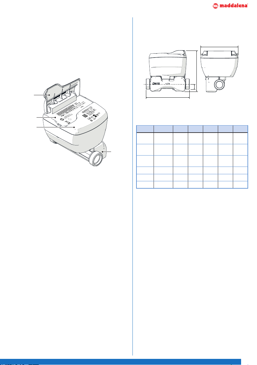
1.5 Structure .......................................................5
1.5.1 Dimensions ..............................................5
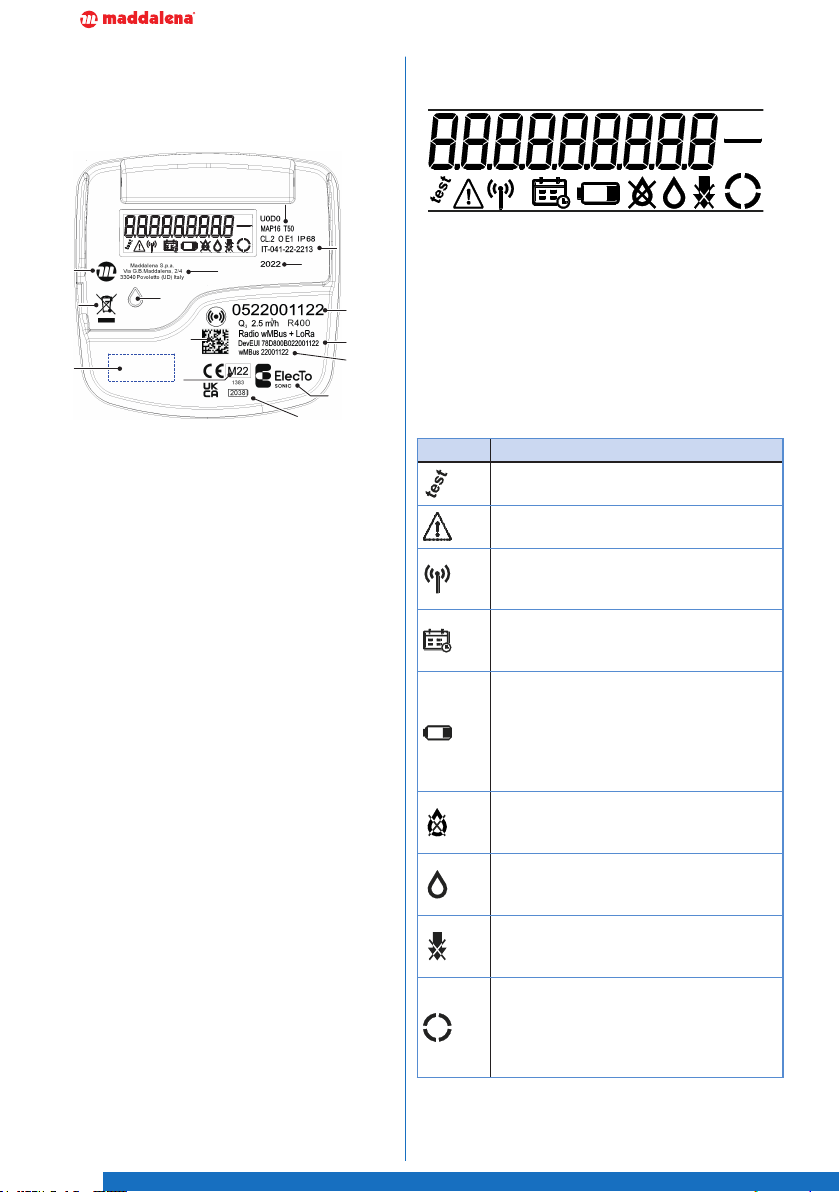
1.6 Identification.................................................6
1.7 Display...........................................................6
1.7.1 Main view..................................................7
1.7.2 Periodic readings.....................................7
1.7.3 Display test and firmware version.........7
1.7.4 Seals ..........................................................7
1.8 Alarms ...........................................................8
1.8.1 Alarm transmission (LoRaWAN mode) .8
1.9 Technical specifications...............................9
1.10 Additional technical specifications...........10
1.10.1 Pressure drop ........................................10
1.10.2 Typical error curve.................................10
1.11 Radio technical specifications...................11
2 Installation. . . . . . . . . . . . . . . . . . . . . . . . . . . . . . . . .12
2.1 Receipt of the product...............................12
2.2 Assembly.....................................................12
3 Use . . . . . . . . . . . . . . . . . . . . . . . . . . . . . . . . . . . . . . .15
4 Configuration . . . . . . . . . . . . . . . . . . . . . . . . . . . . . .15
5 Error codes . . . . . . . . . . . . . . . . . . . . . . . . . . . . . . . .16
6 Test mode . . . . . . . . . . . . . . . . . . . . . . . . . . . . . . . . .16
7 Maintenance . . . . . . . . . . . . . . . . . . . . . . . . . . . . . . .17
7.1 Battery (default) .........................................17
7.2 Cleaning.......................................................17
7.3 Disposal.......................................................17
8 Compliance declaration . . . . . . . . . . . . . . . . . . . . .18

3
1 General information
1.1 Warnings and safety rules
lWARNINGS
– This manual is the property of
Maddalena S.p.A. and reproduc-
tion or transfer to third parties of
the contents of this document is
prohibited. All rights reserved. This
document represents an integral
part of the product; ensure that it
is always together with the product,
even in case of sale/transfer to an-
other owner, allowing its consulta-
tion by the user or authorised main-
tenance or repair personnel.
– Read this manual carefully before
using the device to ensure safe op-
eration.
– The device must be used as intend-
ed by Maddalena S.p.A., which
is not liable for damage caused to
persons, animals or property by
installation, adjustment or mainte-
nance errors or improper use of the
device.
– After unpacking, ensure the deliv-
ery is intact and complete. If it does
not correspond to what was or-
dered, contact the local distributor
who sold you the device.
– The device must be installed and
used in an area protected from
freezing.
– The device must always be pro-
tected from extreme humidity and
heat. Penetration of humidity and
intense heat may damage the bat-
tery and the device. The maximum
allowed operating temperature is
55°C.
– If in doubt about the condition and/
or functionality of the device and its
parts, please contact your local dis-
tributor for further information.
– Once the device has been commis-
sioned, report any faults or mal-
functions found to the product sup-
plier.
– In the event of complete destruc-
tion of the device, with the electro-
lyte escaping, avoid skin and eye
contact with the electrolyte, do not
inhale the vapours produced and
ventilate the room adequately.
– This device is not intended for use
by persons with reduced mental or
motor capacities, or lack of experi-
ence and knowledge (including chil-
dren), unless they are supervised by
a person responsible for their safe-
ty and given appropriate instruction
on how to use the device.

4
1.2 Restrictions
dPROHIBITED
– Modify and/or attempt to repair the
product. All repairs must be per-
formed exclusively by authorised
personnel.
– Leave the device exposed to atmos-
pheric agents.
– Place the device near to heat sourc-
es or expose it to direct sunlight.
– Position the device in proximity of
sources of electromagnetic distur-
bance.
– Open and/or replace the battery.
– Use solvents to clean the device.
– Incorrectly dispose of packaging
material and keep it out of children’s
reach as it may represent a hazard.
Disposal must be performed in line
with applicable laws.
– Dispose of the device as domestic
waste.
1.3 Device description
ElecTo SONIC is a static cold water meter.
It measures the ow volume, ow rate and
other parameter values using ultrasonic
technology. The meter continuously moni-
tors the status of operating and installation
parameters. In the event of a fault, it trig-
gers and sends the dedicated alarms.
ElecTo SONIC is equipped with an integrat-
ed radio which uses Wireless M-Bus and
LoRaWAN technology allowing remote data
transmission. Data can be received using a
special mobile reading kit or via concentra-
tors and a xed network.
The main technical features of ElecTo SON-
IC are:
– Liquid crystal display;
– NFC interface for device conguration;
– Protection class IP68;
– Accuracy class up to R800;
– Fault reporting. Reporting of abnormal
water consumption and error detection
(see Alarms);
– Absence of moving parts. Resistance to
wear and constant functioning over time;
– Datalogging functionality. Historic val-
ues are available relating to: current vol-
ume, backow volume, minimum and
maximum ow rate, water temperature;
– Power supply. Long-lasting lithium bat-
tery (depending on the set conguration);
– Available with built-in wM-Bus and/or
LoRaWAN 868MHz radio communica-
tion.

5
1.4 Usage limits
The product may only be used in accord-
ance with the corresponding limits of use
(see "Technical specications").
1.5 Structure
4
1
2
3
1
Cover;
2
LCD display;
3
NFC area;
4
Meter housing.
1.5.1 Dimensions
B
H
L
h
DN 15 20 25 32 40
inches 1/2" 3/4" 1" 1"
1/4
1"
1/2
Lmm 110 /
165
130 /
190 260 260 300
Thread
inches
3/4"B
- 1"B
1"B 1"
1/4B
1"
1/2B 2"B
Hmm 97 101 110 118 127
hmm 19 21,5 25 29 34
Bmm 94 94 94 94 94

6
1.6 Identication
The ElecTo SONIC meter has its identica-
tion data marked on it.
m3
h
l
1
2
11
10
9
2
13
4
5
14
12
6
7
8
1
15
3
1
QR code
2
LED
3
Manufacturer
4
Meter serial number
5
Measurements
6
Wireless serial number wMBus
7
DevEUI radio LoRaWAN
8
Battery expiration date
9
Space for customer’s logo (optional)
10
MID approval
11
Product name
12
Year of manufacture
13
Manufacturer’s address
14
Type-approval number
15
WEEE marking
1.7 Display
m3
h
l
1
2
The 9 digit LCD shows the data on volume
and ow rate cyclically, as well as any active
error codes.
The display is set in xed mode with the fol-
lowing automatic display cycle:
– for 60 seconds, the Main view;
– for 12 seconds, the Periodic readings;
– for a further 12 seconds, the Display Test
and rmware version.
Icon Description
Test
Activated during test mode
Error
Activated when an error is displayed
Transmission antenna
Signals radio transmission or radio
enabled
Calendar
Activated when billing dates are
displayed
Battery
Activated when the calculated service
life is coming to an end or when the
voltage drops below the minimum
value (in which case the error icon
also lights up)
No ow indicator
Activates when no instrument ow
rate is detected
Leakage
Activated when the leakage alarm is
triggered
Backow
Activated when the reverse ow
alarm is triggered
Star indicator
The indicator, consisting of 2 arc
segments, follows the ow by ro-
tating clockwise for direct ow and
anticlockwise for reverse ow

7
1.7.1 Main view
– The volume measured is displayed for 12
seconds;
– The ow rate is displayed for 3 seconds;
– The display cycle is automatically repeat-
ed 4 times, for a total of 60 seconds (12+3
=15 x 4 =60).
1.7.2 Periodic readings
Following an automatic sequence, billing
date references are displayed:
– Date of reading 1 displayed for 3 seconds;
– Periodic reading 1 displayed for 3 sec-
onds;
– Date of reading 2 displayed for 3 seconds;
– Periodic reading 2 displayed for 3 sec-
onds.
The calendar icon is active during the dis-
play.
1.7.3 Display test and rmware version
The display is presented as follows:
– all segments active for 3 seconds;
– all segments o for 3 seconds;
– the installed rmware version is dis-
played for 3 seconds. The displayed for-
mat is MM.mmF, in which MM indicates
the number (2 digits) of the main version,
mm indicates the number (2 digits) of the
secondary version and Frepresents the
rmware;
– the rmware CRC for 3 seconds. The for-
mat displayed, using all 8 digits of the
display, is 32-bit hexadecimal using both
digits and letters (0-9/A-F);
– any error codes for 3 seconds (e.g. Err
XXXX, where XXXX is the hexadecimal code
for the error). See table "Error codes".
1.7.4 Seals
The meter has a hole (1) at the side of the
body, which is designed for inserting a wire
seal when installing on site.
1

8
1.8 Alarms
ElecTo SONIC is able to detect, store, and
transmit the following alarms via radio:
Alarm
Description
Possible
status
Default
Suspect-
ed leak
Continuous ow
rate detected ON/OFF ON
Backow
Reverse ow
rate for a preset
threshold
ON/OFF ON
Over-con-
sumption
Flow rate exceeds
a threshold for a
preset period
ON/OFF OFF
No con-
sumption
The meter detects
no consumption for
a preset period
ON/OFF ON
Reversed
meter
Constant negative
consumption for
more than 10 days
ON/OFF ON
Ice
The meter receives
no ultrasonic
signal and the
temperature
is below the
minimum threshold
Always
ON ON
Empty
tube/air
The tube is
empty or the
transducers
do not receive
the ultrasonic
signal (possible
damaged
transducer)
Always
ON ON
Low/high
water
tempera-
ture
The meter is
operating outside
envisaged
temperature limits
Always
ON ON
Veri-
cation
period
expiry
The meter has
exceeded the
verication
period
ON/OFF OFF
Low
battery
voltage
Battery voltage is
too low
Always
ON ON
Low
battery
charge
Battery is at ON/OFF ON
Metro-
logical
check-
sum error
The rmware
(ash memory) is
corrupted
Always
ON ON
1.8.1 Alarm transmission (LoRaWAN mode)
– if an alarm condition occurs and the frame
has not yet been sent in the current win-
dow, it is sent early;
– if an alarm condition occurs and the frame
has already been sent in the current win-
dow, an event frame is sent.

9
1.9 Technical specications
Description DN 15 DN 20 DN 25 DN 32 DN 40 U.M.
Accuracy class 2
Ratio Q3/ Q1400
Maximum reading 999999,999 m3
Maximum working
pressure 16 MPa
Temperature class T50: from +0,1 to +50 °C
Sensitivity class for
installation condi-
tions
U0 - D0
Protection class IP68
Power supply LiSoCI2 3.6 V
Useful battery life 16 (Default) years
Environmental and
mechanical condi-
tions
Class O
Storage temperature: -20°C ÷ +60°C
Operating temperature: -10°C ÷ +55°C
Mechanical class M1
Electromagnetic
class E1
Liquid Water
Installation position Any position envisaged by MID
Indicative starting
ow rate 3,0 5,0 7,5 12,5 20,0 l/h
Pressure drop 63 KPa
Available certica-
tions DM174

10
1.10 Additional technical specications
1.10.1 Pressure drop
0,01
0,10
1,00
01
Pressure loss[bar]
Pressure loss -Model: ElecTo Sonic
DN15
DN20
DN25
DN32
DN40
∆p = 0,63
0,01
100,11,0 0,01 Flowrate[m3/h]
10 0
00,01
Q3=2,5m3/h
Q3=4,0m3/h
Q3=6,3m3/h
Q3=10m3/h
Q3=16m3/h
1.10.2 Typical error curve

11
1.11 Radio technical specications
Features Description
Status radio Activation by passage of water (10L)
Conguration Using Android app via NFC (ISO 15693) interface
Standard Wireless M-Bus, OMS
LoRaWANTM v. 1.03 class A
Modes wMBus T1, C1
LoRa SF7-12, BW125-500, CR=4/5
Operating frequency range 863 to 870 MHz
Radiated power 14dBm max
Transmission distance* Up to 15Km in LoRaWANTM
Up to 500mt in wM-Bus
Device class Radio class 1
Data sent
LoRaWAN (OTAA)
- measurement data transmission (alarms, hourly/daily
consumption) twice a day
- supervision data transmission (alarms, device status
information) once a week
wM-Bus
- Tiny frame (default): current volume, date and time,
volume on billing date, billing date, errors
- Short frame: current volume, volume on billing date,
meter serial number, alarms
- Long frame (n C1 mode only): same as short frame with
the addition of values from the last 12 months
* in line of sight
Factory radio
conguration Single mode Dual mode
wM-Bus wM-Bus LoRaWAN
Data sent
Tiny Frame C1: current
volume, date and time,
volume on billing date,
billing date, errors
Tiny Frame C1: current
volume, date and time,
volume on billing date,
billing date, errors
Current volume, date and
time, volume on billing
date, billing date, errors,
daily consumption up to 7
previous days, alarms
Transmission time 08:00 - 18:00 08:00 - 18:00 00:00 - 24:00
Transmission fre-
quency 30secs 30secs 2per day
Encryption active active native
Alarms (default) backow (100 litres), suspected leak (observation frequency 15 min / observation
period 48 hours), max ow rate (disabled)
Battery Duration 18 years 16 years

12
2 Installation
2.1 Receipt of the product
1x
Optional accessories:
– Fittings kit
– Gasket kit
– Gasket
– Non-return valve
lWARNING!
The instruction manual is an inte-
gral part of the device and should
therefore be read and stored
carefully.
dPROHIBITED
Packaging material must be prop-
erly disposed of and kept out of
children’s reach as it may repre-
sent a hazard. Disposal must be
performed in line with applicable
laws.
2.2 Assembly
Authorised personnel: specialised installer
or plumber, assigned by the metering oper-
ator.
lWARNING!
Only authorised and suitably
trained personnel with sucient
technical experience may install
and operate the device.
Before installing the device, make sure that
the two sections of tube are even to prevent
mechanical stress, clean them with care (es-
pecially in the case of empty tubes) and let
water run for a while, using a stub pipe on
the tube instead of the meter.
If there is no water in the pipeline, open the
valve upstream of the device before install-
ing it. This is necessary because opening
the valve after installation is complete may
cause air suction that could damage the de-
vice.
Before using the meter, rst fully remove air
from the pipe and the device itself. The in-
terception/adjustment valves must be fully
open when doing this. Open the valve at the
start rst and then the valve at the end.
When replacing the meter, it is recommend-
ed to replace the gasket on the tting. Rec-
ommended gasket hardness: minimum 80
Shore A.
Tighten the nut with a torque wrench and
use a counter wrench to hold the meter in
position. Maximum tightening torque: 40
Nm.

13
Install the meter:
– protected from frost (insulate it if necessary with insulation material) and in the lower
part of the system to prevent air accumulation;
– protected from blows and tampering, where readings are easy to make;
– so that the direction of the arrow on the device coincides with the ow direction.
Install proper interception valves upstream and downstream of the meter to permit main-
tenance operations and inspections on the device, as well as to check the system.
The installation of a non-return valve inside or outside the meter is also recommended (see
dedicated data sheet).
lWARNING!
Before positioning the seal, make sure that it is not damaged.
Make sure that the seal is not damaged during installation.
Make sure that the level of the seal matches that of the tubing.
Check that the seal does not protrude from the tube.
Make sure that the surfaces of the ange are clean and undamaged.
lWARNING!
Check the seal hold to prevent leakage.

14
Installation position
Observe the indications on the dial (letters
H and V):
– H: the meter must be installed with the
dial in a horizontal position;
– V: the meter must be installed with the
dial in a vertical position;
– H and V: the meter may be installed with
the dial in either a horizontal or vertical
position;
– If not shown, avoid vertical installations
with downward ow, or with the dial fac-
ing downwards.
Straight sections and ow straighteners
When using straight sections upstream and/
or downstream of the meter, refer to letters
U and D on the dial. If the letters U and/or
D are followed by the letter S, install a ow
straightener.
Allowable water pressure (ISO 4064-1)
The maximum allowable pressure (MAP) is
16 bar, and is displayed on the meter dial. If
not indicated on the dial, it must be 10 bar.
These values must never be exceeded.
The maximum allowable pressure (MAP)
downstream of the meter must be greater
than or equal to 0.03 Mpa (0,3 bar).
Commissioning
Before putting the meter into operation,
completely vent the air from both the pipe
and the meter itself (rotate it if necessary).
The interception/adjustment valves must be
fully open when doing this. Open the valve
at the start rst and then the valve at the
end.

15
3 Use
ElecTo SONIC is ideal for domestic and in-
dustrial usage and, thanks to the absence
of moving parts, it is resistant to wear and
ensures constant functioning over time.
The measurements taken by the meter are
shown cyclically on the display and are also
available on other communication interfac-
es.
The water meter is not suitable for installa-
tions where the water is particularly heavy,
sandy, rich in algae, sludge and debris, or
contains air.
The normal operating phase is remote me-
ter reading through radio modules. In AMR
(xed) mode, each radio module (wMBus
and/or LoRaWAN) transmits the reading at
a programmable frequency.
In mobile mode (Walk-By/Drive-By), the ra-
dio module wMBus emits a data frame with
the measurements. To receive the radio
module signal, hold a suitable receiver near
the meter. The xed (AMR) system reads
data automatically.
lWARNING!
Data can be read using a variety
of software. Please refer to the
accounting manager for specic
usage information on the reading
software.
lWARNING!
It is recommended to keep the lid
closed once the installation steps
are completed.
4 Conguration
ElecTo SONIC is supplied with a default
conguration.
The radio is activated after the passage of
10 litres of water.
The NFC programming interface is available
at all times by positioning the special set-
tings kit above the designated area. The to-
tal available cumulative programming time
is 18 hours.
NFC Ar
ea
The radio settings, such as the type of ra-
dio frame and data transmission frequen-
cy, have a default factory setting. However,
they can be changed, if necessary, after
making the device programmable, via the
appropriate kit:
– App ElecTo SONIC (Android, downloada-
ble from Google Play Store);
– Smartphone with NFC or UniCo Tool inter-
face.
For further information, contact the manu-
facturer.
The app allows the following parameters to
be read and programmed:
– Radio settings
– Radio AES key
– Periodic reading
– Alarms setting
– Alarms reset
– Date/time synchronization
– Delivery point

16
5 Error codes
The error code is displayed in hexadecimal
format.
The instrument identies 6 errors which
may also occur simultaneously.
Hexadecimal format Description
0080 Out Of Operating
Temperature
0100 ICE
0400 Low Battery Voltage
1000 Metrological verication
period expired
4000 Metrological Wrong
Checksum
8000 General Fault
Example of simultaneous errors
Low battery voltage + Metrological verica-
tion period expired: Err 1400
6 Test mode
ElecTo SONIC can be temporarily set to a
high resolution in order to carry out meas-
urement tests.
Contact the manufacturer for further infor-
mation.

17
7 Maintenance
7.1 Battery (default)
The meter is tted with a lithium battery
3.6V that cannot be recharged or replaced.
The estimated lifespan of the battery is cal-
culated using factory set-up and with the
following operating conditions:
– from -10°C to +0°C for 10% of the lifespan
– from 1°C to +30°C for 80% of the lifespan
– from +31°C to +55°C for 10% of the
lifespan
lWARNING!
Humidity and intense heat may
damage the battery and reduce
its lifespan.
The device calculates the useful remaining
life of the battery based on memorized pa-
rameters, for example, estimated consump-
tion of the electronic board in standby, con-
sumption in transmission and the number
of transmissions made.
Battery life depends on the data transmis-
sion frequency you choose to set.
aDANGER!
If the battery is empty, it is nec-
essary to contact the metering
operator for the correct replace-
ment procedure.
The battery must be disposed
of in compliance with applicable
laws on waste disposal in the
country of installation.
7.2 Cleaning
No particular cleaning procedures are re-
quired. However, the installation area
should be kept clean and periodic checks
should be performed to ensure the required
environmental conditions are met.
dPROHIBITED
It is forbidden to use abrasive
products, methyl alcohol, hy-
drochloric acid (35%), sodium
bicarbonate (10%), tricresyl phos-
phate, benzol, concentrated eth-
anol, toluol, industrial petrol,
methylisobutylketone, acryloni-
trile, cosmetic solvents, sodium
hydrate (10%), ammonium hy-
drate (10%), nitric acid (40%), po-
tassium dichromate, acetone,
diesel naphtha, petrol.
7.3 Disposal
The device is made from various materials
such as: metal and plastic materials, electri-
cal and electronic components. It must be
disposed of in accordance with current local
regulations on industrial and special waste.
It must not be disposed of with household
waste.
The device does not contain any toxic/haz-
ardous substances or elements, including
lead, mercury, cadmium, hexavalent chro-
mium, polybrominated biphenyl.
At the end of the product’s life, ensure safe
removal and responsible disposal of com-
ponents, including recycling of batteries, in
compliance with applicable environmental
laws in the country of installation.

18
8 Compliance declaration

19

MADDALENA spa
Via G.B. Maddalena 2/4 - 33040 Povoletto (Udine)
Tel. +39 0432 634811
www.maddalena.it
Maddalena S.p.A. reserves the right to change its products at any time and
without prior notice, with the aim of improving them and without compromising
primary features. All the graphic illustrations and/or photographs appearing in
this document can be represented with optional accessories that vary in relation
to the country where the device is used.
Table of contents
Other MADDALENA Measuring Instrument manuals

MADDALENA
MADDALENA QuadraPlus User manual

MADDALENA
MADDALENA ElecTo Bulk User manual

MADDALENA
MADDALENA microCLIMA U User manual

MADDALENA
MADDALENA microCLIMA U User manual

MADDALENA
MADDALENA ElecTo SJ Parts list manual

MADDALENA
MADDALENA ArrowEVO Parts list manual

MADDALENA
MADDALENA ElecTo SJ Parts list manual

MADDALENA
MADDALENA Arrow Mobile Android User manual

MADDALENA
MADDALENA ElecTo SJ Parts list manual

MADDALENA
MADDALENA microCLIMA User manual