Akva AKVAconnect 4.1 User manual

USER MANUAL
AKVAconnect 4.1
Technology for sustainable biology

Thank you for choosing AKVA group
AKVA group develops, manufactures and supplies
technology and services aimed at solving biological and
technical challenges in the global aquaculture industry.
All our products, from single components to service
assignments and complete farms, are designed to achieve
the best possible sh welfare, operational performance and
protability for our customers.
We aim to write easy to understand user manuals, while
providing as accurate and updated information as possible.
In order to do this, we rely on input, feedback and
collaboration with people who use our products. We
appreciate all the input we have received, as this helps
us provide better and safer equipment and solutions.
Please contact us through our websites with questions or
suggestions for improvements.
This manual is written in correlation with the requirements in
the standard “NEK EN 82079-1”.
Unless such responsibility has been agreed upon in a
separate written contract with AKVA group, we are not
responsible for loss, damage or incorrect use of equipment or
software that arises as a result of errors in text or illustrations, or
by following instructions in this user manuals.
For a thorough introduction to your AKVA group product,
carefully read through this user manual before assembling,
installing or using the product. Most of our user manuals are
available from our website: www.akvagroup.com/products/
user-manuals.
Together we can contribute to making sure that sh farming is
an environmentally friendly, sustainable and growing industry
that produces safe and healthy seafood for a global market.
Best regards,
AKVA group

3
3 35av
TABLE OF CONTENTS
1 SAFETY.............................................................4
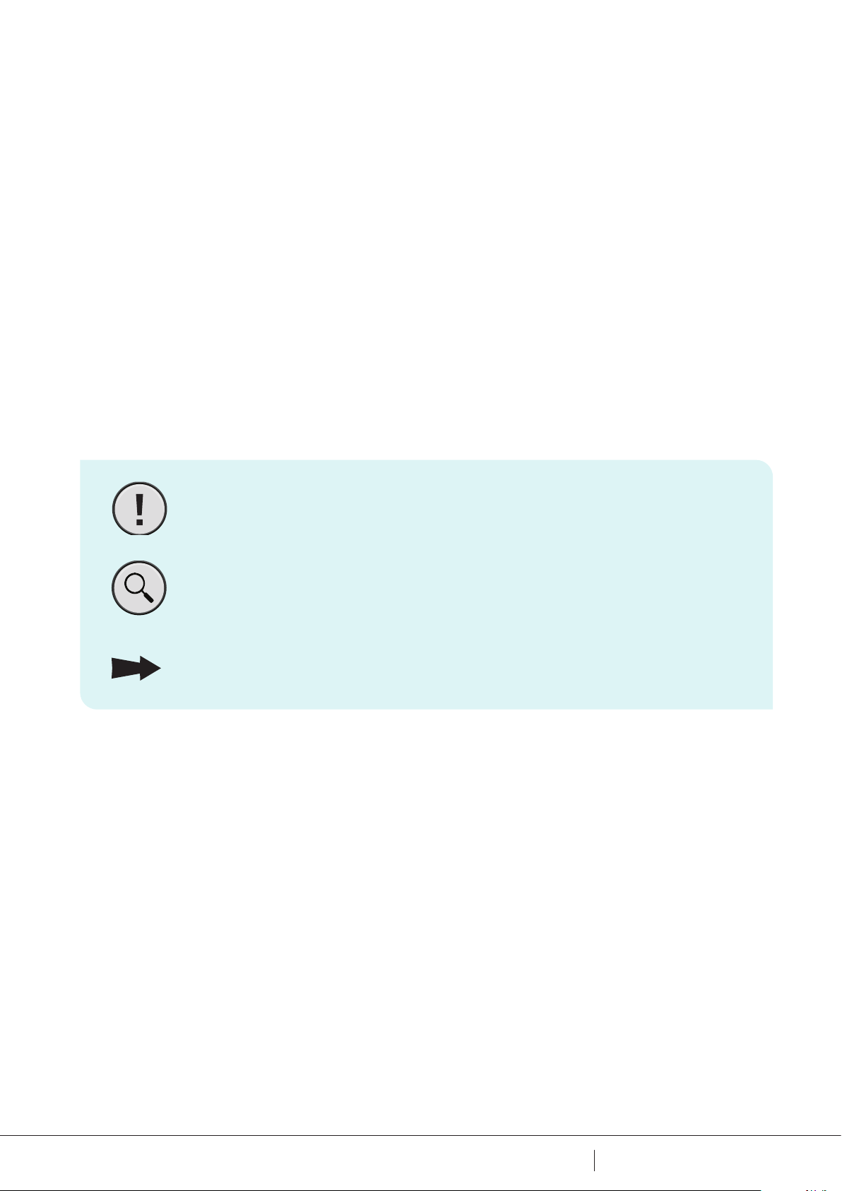
1.1 Safety symbols ......................................................4
1.2 Personnel safety .....................................................5
1.3 Technical condition for equipment .........................................5
2 INFORMATION.......................................................6
3 START UP ...........................................................7
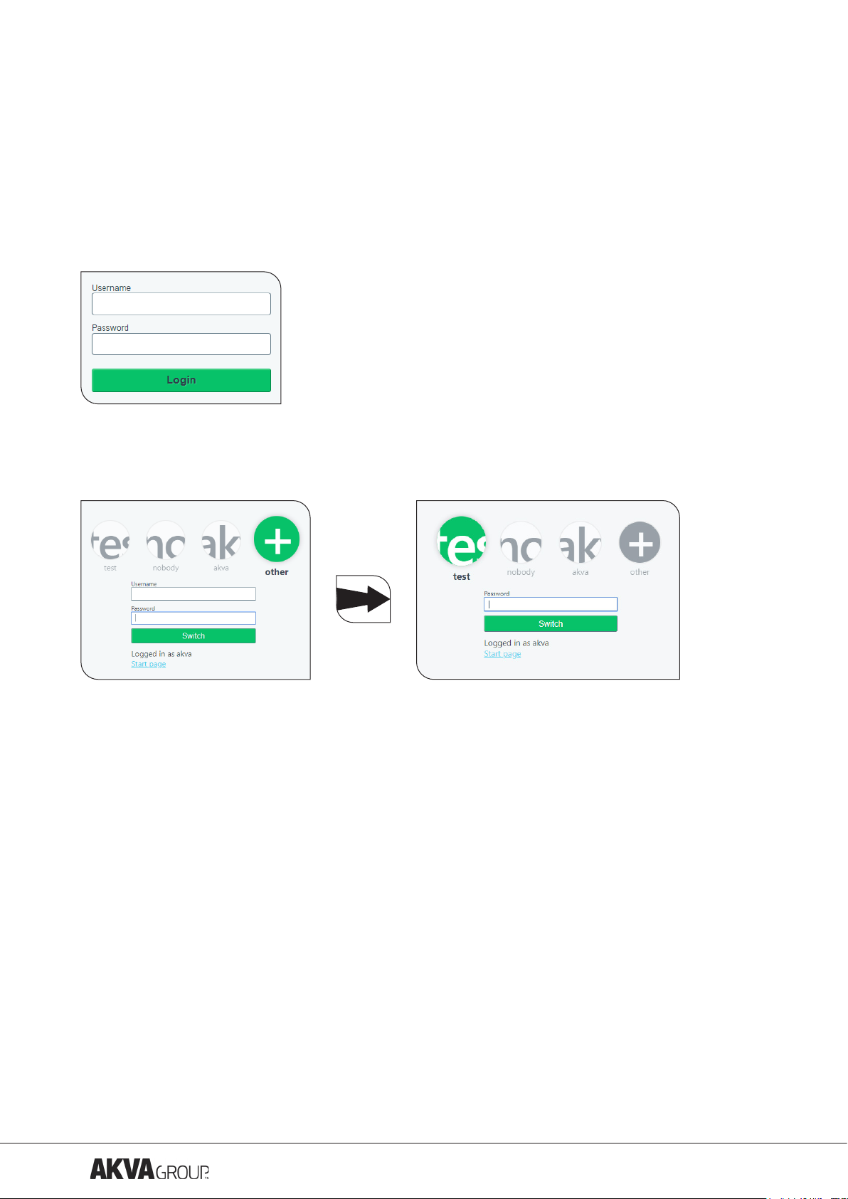
3.1 Log in ............................................................7
3.2 Log o ............................................................7
3.3 Users and roles ......................................................7
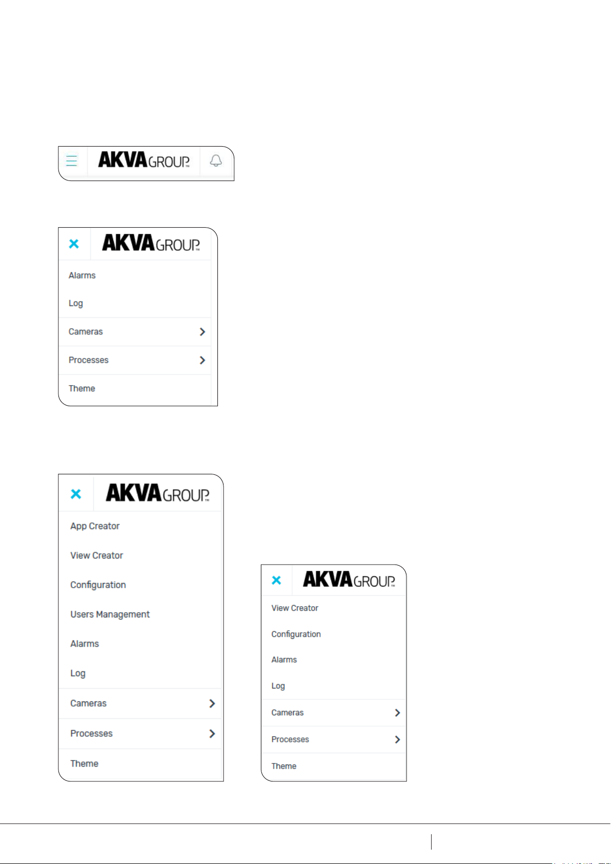
3.4 Main menu .........................................................8
3.5 Navigation footer.....................................................9
4 THEME ............................................................11
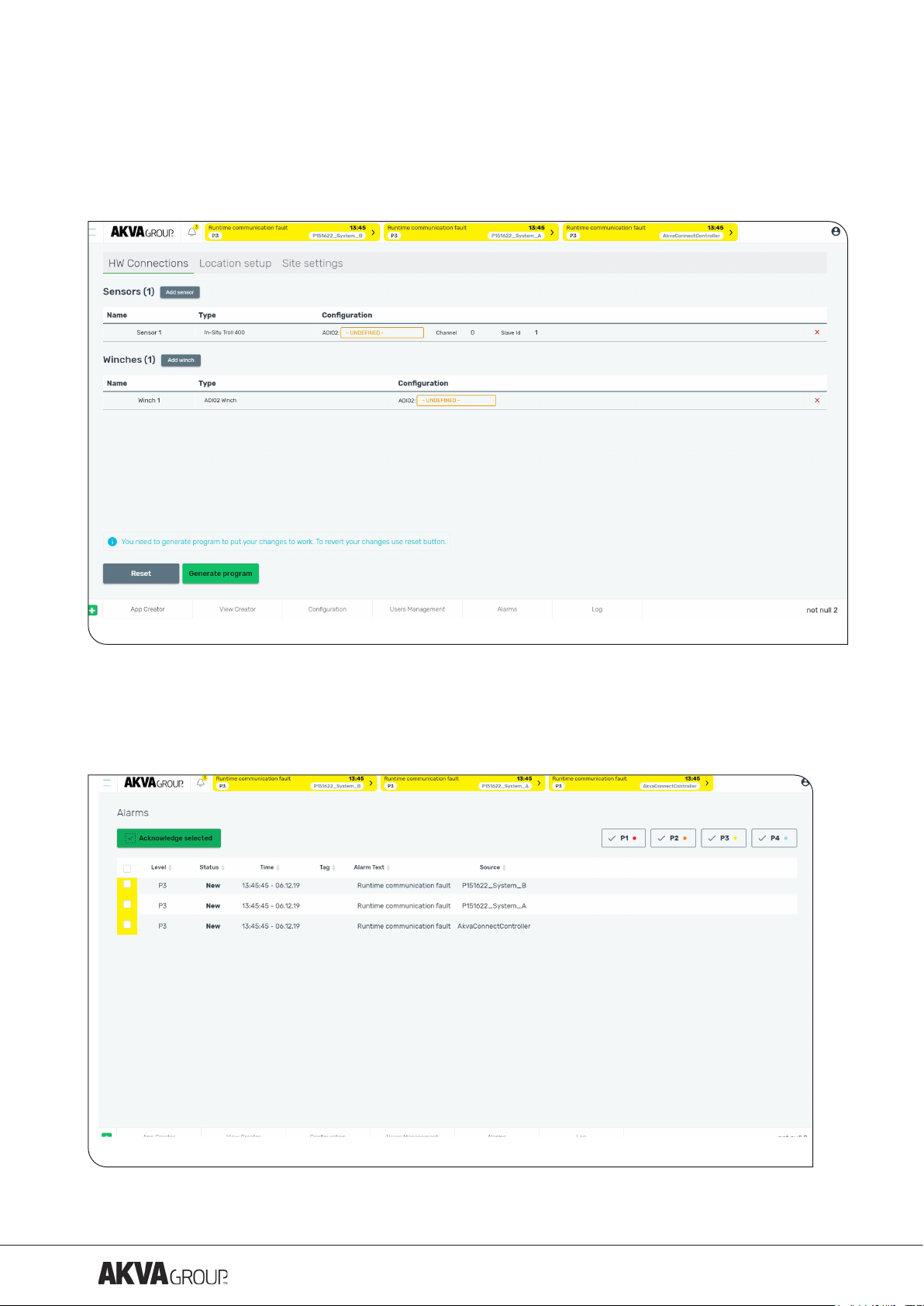
5 APP CREATOR ......................................................12
5.1 Connecting hardware .................................................13
5.1.1 Add sensor or winch ................................................13
5.1.2 Remove sensor or winch .............................................14
5.2 Setting up location. . . . . . . . . . . . . . . . . . . . . . . . . . . . . . . . . . . . . . . . . . . . . . . . . . . 14
5.2.1 Add and congure camera ............................................14
5.2.1.1 Add sensors to a camera............................................15
5.2.1.2 Remove sensors from a camera .......................................16
5.2.2 Remove camera ...................................................16
5.2.3 Add and conkgure camera location .....................................16
5.2.4 Remove camera location .............................................16
6 VIEW CREATOR .....................................................17
7 CONFIGURATION....................................................20
7.1 Alarm conguration ..................................................20
7.2 Winch Conguration..................................................20
7.3 Sensor reset .......................................................21
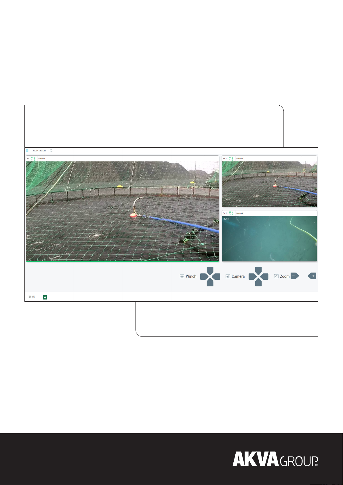
8 CAMERA ...........................................................22
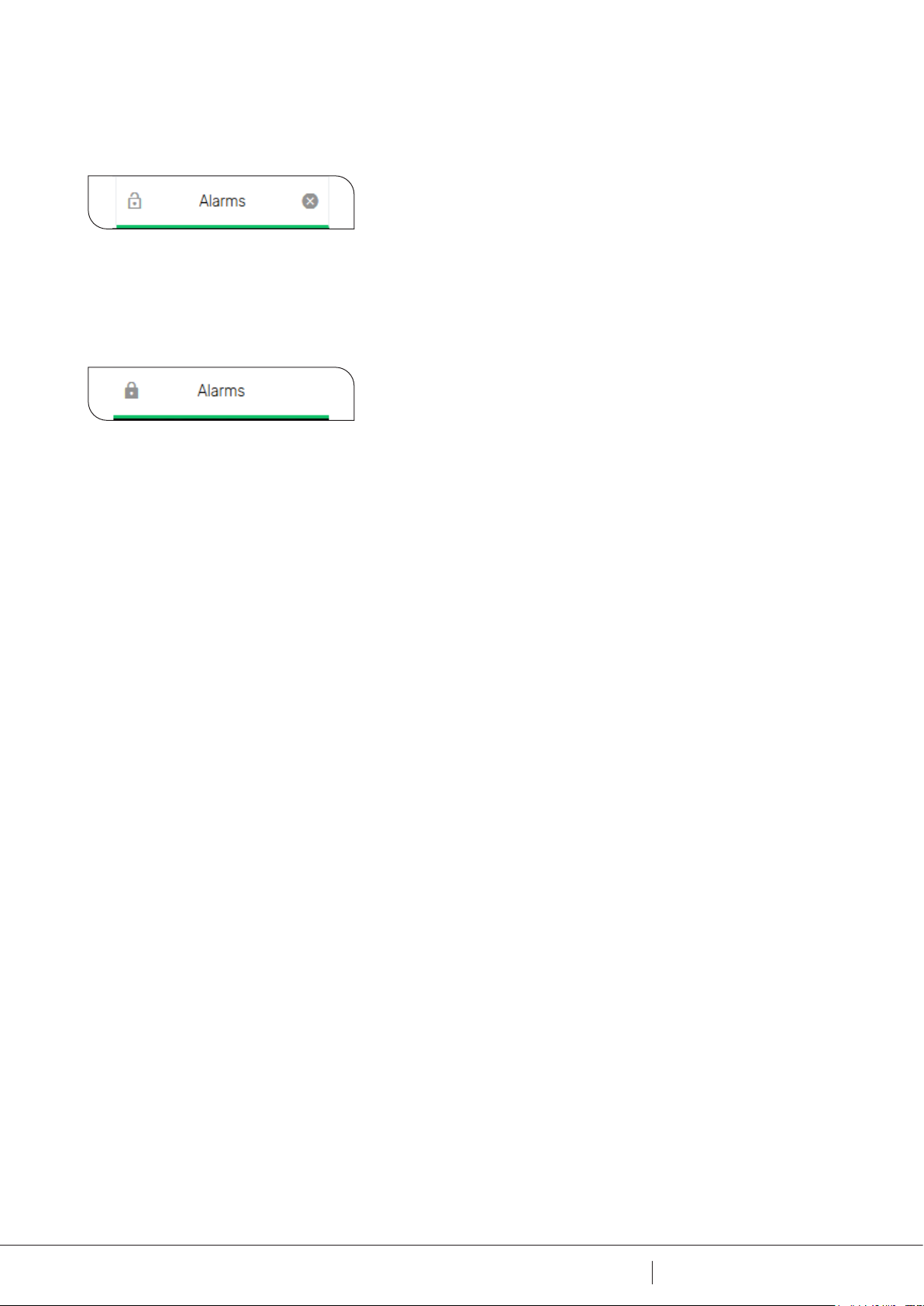
9 ALARMS ...........................................................24
10 LOG28
10.1 System log .......................................................29
10.2 Debug log ........................................................29
10.3 Audit log.........................................................29
10.4 Alarm log ........................................................29
APPENDIX A - DEVIATION FORM ........................................30
APPENDIX B - NOTES ..................................................31
APPENDIX C - CAMBIUM EPMP 1000......................................32
APPENDIX D - RACK AKVACONNECT ......................................33

4
4 35av
DOCUMENT NO:
DC10001590 A
REVISION NO:
1 SAFETY
Safety for the users of our equipment is main focus when AKVA group ASA develop new products
and product manuals.
We strongly recommend that everyone who are going to be using the AKVA product, all who
perform any type of repairs, service or other maintenance to AKVA products, and all who work in
areas where such products are installed, are aware of the contents in this manual.
This recommendation is based on both personnel safety as well as a desire to keep AKVA
products in order, and to avoid risk of damages as a result of not following safety instructions.
1.1 SAFETY SYMBOLS
NOTE!
Material damage - Symbol that signals a warning regarding a situation that
may cause damage on equipment or surrounding items.
TIPS!
Symbol that signals useful hints and recommendations for eective use of
the software.
GO TO
Click on the Underlined text to go to, or see page, section or other
document for further instructions or more information.

5
5 35av
When remote controlling winch from the barge, anyone staying on the cage edge must be aware
of this operation. Read both this AKVAconnect manual as well as user manual for camera with
and without winch before installing and using these.
Camera, winch and other equipment shall never be operated when they are not installed
properly. To prevent use of equipment that is not properly installed, follow the procedures
in the applicable installation manual.
Equipment shall never be operated when they are not in perfect technical state. To prevent use
of defect equipment, follow the procedures in the applicable maintenance manual.
If any of the equipment is operated in defective condition, safety features and availability will be
weakened.
Manual for Akvasmart Camera with and without winch and other relevant manuals may be read
and downloaded from www.akvagroup.com/products/user-manuals.
Use only original spare parts supplied by AKVA group. Unauthorized rebuilding and modications
of the equipment is strictly prohibited.
1.2 PERSONNEL SAFETY
GO TO
All relevant AKVA product user manuals are found here:
www.akvagroup.com/products/user-manuals.
1.3 TECHNICAL CONDITION FOR EQUIPMENT

6
6 35av
DOCUMENT NO:
DC10001590 A
REVISION NO:
2 INFORMATION
This manual applies to AKVAconnect 4.0, and is to be regarded as part of the product
equipment. Keep the manual for as long as your AKVA product is in use, and note any changes
in the back of this manual as they are performed.
The purpose of this manual is to enable the user to install and Use AKVAconnect in a safe and
economically sustainable way. All instructions given in this manual must be followed. Site owner
is responsible for keeping the manual available for all personnel as long as the product is in use.
Do not hesitate contacting us if additional information about installation, use and troubleshooting
is required. If there are questions that are not answered in this manual, please contact us to
nd a solution to the problem. Contact our service department, your local supplier, your nearest
AKVA oce or our main oce in Norway.
NOTE!
Some of the illustrations in this manual may dier from what shows on the
screen. And although some illustrations have black theme and some will
have the light theme, the contents of the illustrations will be the same.
NOTE!
This entire manual must be read and understood prior to installation
of AKVAconnect, as well as used as aid during installation, use and
troubleshooting.

7
7 35av
3 START UP
3.1 LOG IN
Start up the program by clicking on the icon. To log in, type user name and password and click
Login.
When someone has logged in, their user name will appear as an icon over the login setup. Click
on the desired icon to select it, type the belonging password, and select Switch to log in.
Up to 3 previous users are listed over the login setup, as icons with names below.
When logged in, the user will be logged also when opening new browsers and windows. When a
user logs o, they will be logged o in all active browsers.
3.3 USERS AND ROLES
3.2 LOG OFF
When a user signs out, they will be logged o in all active browsers.
A user is able to Add, Delete, Edit, Activate, Deactivate and Change role. The display will change
the display according on access level for the user that is currently logged in.
4 dierent user groups:
• Basic users: only access to operate and view system components they have access to.
• Advanced users: have access to a limited menu.
• AKVA Engineers: have access to everything.
• Site manager: full access with admin tools. Will not see debug information

8
8 35av
DOCUMENT NO:
DC10001590 A
REVISION NO:
3.4 MAIN MENU
Click the icon to open the Main Menu. For a user with basic access this menu will pop up:
The Main Menu icon consists of three parallel horizontal lines, and is found in the top left corner
of the window.
AKVA Engineers will nd the full menu, and Advanced users will have access to the limited
menu:

9
9 35av
3.5 NAVIGATION FOOTER
The Navigation footer is found in the bottom of a AKVAconnect window. When opening a view
from the Main Menu, a tab will appear in the Navigation Footer.
For example, when Alarm is selected from the Main menu, the Alarm list will appear in the main
view, and an Alarm tab will appear in the Navigation Footer.

10
10 35av
DOCUMENT NO:
DC10001590 A
REVISION NO:
When holding the mouse pointer over the tab, a pad lock symbol will appear in the left side of
the tab.
When the pad lock is open, and has no ll, the lock is open. This means that the tab will be
removed when the Alarm view is closed. To lock the tab to the Navigation Drawer, click on the
pad lock. This will change the pad lock appearance, it will appear locked, and will be lled with
color.

4 THEME
To change theme, click Main Menu and select Theme. This will change from light to dark theme,
or from dark to light.
Example with the dark theme:
Example with the light theme:
11
11 35av

5 APP CREATOR
To open the AppCreator, click the Main Menu icon on the left, and select AppCreator to open.
A new window opens, showing all an empty AppCreator for the current site.
Click on «Site Settings» and enter a name for the site. Here, the name is «Demo site».
SMS Sender
If you have a teltonika sms sender you can set it up to send alarms on sms:
Check o Enable
Select type
Enter IP-adress
(See chapter 7 for details about the alarm conguration)
After making changes, such as adding or removing sensor, winch or camera, remember to
always Generate Program, by clicking this button:
12
12 35av
DOCUMENT NO:
DC10001590 A
REVISION NO:

Click on «HW Connections».
To add a new sensor or winch:
1. Click on «Add sensor» or «Add winch».
2. Then select the type of sensor or winch from the drop down list shown in type.
3. In conguration, select the ADIO2 card the device is connect to, or enter the IP to the
device.
If the device does not appear, press «F5» on your keyboard to reload the drop down lists.
4. Click on the green «Generate program» button to make your changes permanent.
Here, one sensor and one winch is added:
5.1 CONNECTING HARDWARE
5.1.1 ADD SENSOR OR WINCH
13
13 35av

14
14 35av
DOCUMENT NO:
DC10001590 A
REVISION NO:
To remove a sensor or winch, click on the red cross to the right for the device that is going to be
removed.
Click on the green «Generate program» button to make the changes permanent.
5.1.2 REMOVE SENSOR OR WINCH
5.2 SETTING UP LOCATION
Click on «Location setup» in the «App Creator».
This is where the cameras are added and grouped together for dierent locations.
A location example is a specic pen, but it could also be all top cameras, surface cameras and
similar.
Click «Add cameras» in the Location setup area.
5.2.1 ADD AND CONFIGURE CAMERA
Name the camera and select the physical camera in the Device column.
Here, it is also possible to connect one winch (select from the drop down menu) and sensors
(see section 6.2.1.1 Add sensors to a camera) to the camera.
Here is an example of three cameras with winches and sensors set up in AKVAconnect:

15
15 35av
Click the green «Generate program» button to make the changes permanent.
Here are all available/created sensors are.
Filter among the sensor types to make it easier to nd the right sensor, by clicking on the
desired tab. For example: click on Temperature to nd all available temperature sensors.
«Pen 1 UW» are default sensors installed in underwater cameras, these sensors read
temperature and depth.
To add a sensor, click on the desired sensor and the click on «Add sensor»
5.2.1.1 ADD SENSORS TO A CAMERA
Click the green and white + symbol in the Sensors row to open this window:

Click «Add location».
5.2.3 ADD AND CONKFIGURE CAMERA LOCATION
Change the default name if needed. Here «Pen 1» is default name.
To add cameras to the location «Pen 1», click on the desired camera name(s).
Here, three are cameras added to the location Pen 1:
16
16 35av
DOCUMENT NO:
DC10001590 A
REVISION NO:
5.2.1.2 REMOVE SENSORS FROM A CAMERA
To remove a sensor from a camera, click on the black and white X next to the sensor name.
A red cross is found to the right of every camera row. Click this cross to remove the current
camera.
Click the green «Generate program» button to make the changes permanent.
5.2.2 REMOVE CAMERA
A red cross is found to the right of every location row. Click this cross to remove the current
camera.
Click the green «Generate program» button to make the changes permanent.
5.2.4 REMOVE CAMERA LOCATION

6 VIEW CREATOR
It is possible to select ve dierent layouts, showing 1, 2, 3, 4 or 6 camera view layouts.
1. Name the layout, for instance “3 split”.
2. Choose Camera Ratio (must be in accordance with the cameras that are going to be used in
this particular view).
3. Choose Layout for the view.
4. Click Create view to set up, and the set up will appear in a new window.
Here is an example of how the view will look like. The view name is “3 split”, ratio is set to 16:9,
and layout with 3 split is chosen.
17
17 35av

In the top left corner is a menu called ‘select’. Here it is where the cameras are added to the
view. Click ‘select’ and ‘More’ and the camera selection window will appear.
In the ‘Other sources’ list, select the correct Pen, and the cameras that are connected to this pen
will appear in a list in the right side of this window:
18
18 35av
DOCUMENT NO:
DC10001590 A
REVISION NO:

All views will have the possible camera sources available for selecting.
Selecting the All-source will enable the user to select all cameras, in the order they are set
up in the AppCreator.
Selecting the Pen 1-source will enable the user to select all cameras listed in
Pen 1 = Surveillance, Up and Down, as set up in the AppCreator.
Selecting the Pen 2-source will enable the user to select all cameras listed in
Pen 2 = Surveillance, Up and Down, as set up in the AppCreator.
It is possible to add the same source to several views.
Click Save & open when all views have a source selected.
19
19 35av

7 CONFIGURATION
To open the conguration, click Main Menu and select Conguration. A new window opens,
showing Alarm conguration, winch conguration and sensor conguration.
Alarm conguration contains 2 dierent groups. The PLC alarm with light control and horn,
reqires process control. SMS sending based on alarm level, requires SMS sender.
Here is an example of how the alarm conguration window may look like:
7.1 ALARM CONFIGURATION
7.2 WINCH CONFIGURATION
20
20 35av
DOCUMENT NO:
DC10001590 A
REVISION NO:
Table of contents
Other Akva Fishing Equipment manuals
Popular Fishing Equipment manuals by other brands

Aquapro Fish Feeders
Aquapro Fish Feeders ATX Product information guide

Avet Reels
Avet Reels Fishing Reel Pro EX 4/02 parts list

Scotty
Scotty LINE PULLER Installation, Maintenance, Use and Safety

Avet Reels
Avet Reels Fishing Reel MXL 5.8 parts list

Belitronic
Belitronic BJ5 Operating and service manual

STRIKEMASTER
STRIKEMASTER Solo owner's manual