Alamo Superior Equipment LXSP Series Programming manual

LXSP SERIES
LXSP5
SUPERIOR EQUIPMENT
Phone: (07) 4691 1500
Email: sales@alamoag.com.au
Website: www.superiorequipment.com.au
OPERATOR & PARTS MANUAL
(c) 2017 Superior Equipment Pty Ltd

2 © 2017 SUPERIOR EQUIPMENT PTY LTD
LXSP5 SERIES
Model Width Weight HP (Min)
LXSP 5 1.5m / 5’ 700 kg 50
Specifications
•EHD Gearbox
•Two Depth Control Wheels to Front with hydraulic body
tilt
•One 500x10 Wheel to Rear
•Galvanised Body
•Hydraulic control side chute
•Tilt Adjusting Tower

5 © 2017 SUPERIOR EQUIPMENT PTY LTD
TABLE OF CONTENTS
CORPORATE PHILOSOPHY....................................................... 3
INSTRUCTION MANUAL & SPARE PARTS LIST ...................... 4
WARRANTY CONDITIONS.......................................................... 6
LIABILITY & LEGAL ISSUES ...................................................... 7
DEALER PRE-DELIVERY AND INSTALLATION
CHECKLIST.................................................................................. 8
OPERATIONAL SAFETY INSTRUCTIONS................................. 9
OPERATING INSTRUCTIONS................................................... 12
INITIAL START UP ................................................................................................................. 12
Attaching Tractor .............................................................................................................. 12
Setting Up Your Soil Profiler ............................................................................................ 13
Setting Up Your Blades .................................................................................................... 14
OPERATION ........................................................................................................................... 14
Clutch Settings .................................................................................................................. 14
Clutch Adjustment ............................................................................................................ 15
GENERAL MAINTENANCE ................................................................................................... 15
LXSP 5 SERIES ASSEMBLY .................................................... 16
PROFILING HEAD ASSEMBLY ................................................ 19
GEARBOX ASSEMBLY ............................................................. 20
CLUTCH ASSEMBLY ................................................................ 22
FRONT WHEEL ASSEMBLY..................................................... 23
CASTOR WHEEL ASSEMBLY .................................................. 24

12
OPERATING INSTRUCTIONS
Getting the best from your Superior Slasher
INITIAL START UP
Check Gearboxes for oil daily: Recommended OIL: 85w -- 140 EP GEAR
OIL.
Gearbox level plug is located at side of gearbox, correct oil level is at the
top of the hole where the oil plug screws in.
Prompt attention to oil leaks is essential.
Grease all grease points: Recommended Grease: All Purpose Grease
EPL 2
Attaching Tractor
Connect tractor to TPL lower link pins. The Profiler is fitted with a stepped
pin which will fit either cat 1, 22 mm ( 7/8” ) or cat 2, 30 mm ( 1 1/8” ).
Make sure tractor is fitted to correct size and place lynch pin in hole end of
pin.

13
Tighten anti-sway bars / chains (must be firm, not rigid)
Connect top link to tower.
Connect driveshaft to P.T.O. on tractor and clutch / gearbox on profiler,
make sure clamp bolts and or Q.R. pins are located in respective grooves.
(Failure to do this will result in driveshaft damage).
Tractor lift arms can vary in length. CHECK OPERATIONAL LENGTH OF
DRIVESHAFT BEFORE OPERATING PROFILER.
Check length of driveshaft at the highest and lowest positions of tractor lift
arms.
The driveshaft requires sliding movement of approx. 100 mm (4”) to avoid
bottoming or pulling apart at maximum operational lengths.
Caution entering & exiting steep gullies or steep ridges may result in drive
shaft bottoming out or coming apart. Check drive shaft length before using
Profiler in extreme conditions.
Setting Up Your Soil Profiler
Soil profiler should be set up to the correct profiling height by adjusting
front steel wheels, side skids, hydraulic adjusted tower, and hydraulic
adjusted chute.
The rear of the machine is adjusted by the rear wheel by placing the bolt in
the higher or lower position.
Profiler should be set at a level stance when viewed from the side. PTO
speed is critical, it is best to keep engine revs up.
To achieve optimum results, give PTO max torque (Optimum Blade Tip
Speed), ground speed can then be adjusted by using lower gear in heavy
going and higher gear in light going.

14
Setting Up Your Blades
Check that profiling blades are fitted tightly and correctly to the profiler
spindle.
Check that profiler blades are tight, inspection should be carried out daily.
If holes are elongated, it is recommended that replacement blades, bolts &
nuts be fitted immediately.
OPERATION
CUTTING DEPTH –
For best mowing results maintain correct PTO speeds
In heavy going or awkward areas change back a gear or reduce forward
speeds rather than reduce PTO speed by throttling back
CAUTION: Entering & exiting steep gully's or steep ridges may result in
drive shaft bottoming out or coming apart, check drive shaft length before
using Profiler in extreme conditions.
Clutch Settings
Clutch settings are best set up in conditions that the Profiler is operating
in.
€Operate the Profiler in reasonably heavy conditions for approx. 20
to 30 minutes.
€Switch engine off, remove key from ignition
€Disengage PTO
€Check temperature of clutch with EXTREME CAUTION by placing
hand near clutch, if clutch is warm to the touch it is about right, if it
is too hot to touch or hot to the touch the clutch has been slipping
excessively and adjustment is necessary.

15
Clutch Adjustment
€Undo lock nuts
€Tighten (increase spring tension) or loosen (decrease spring
tension) adjusting nut by ¾ of a turn
€Make sure each of the nuts is adjusted in turn.
€Do up lock nuts
€Refer back to Clutch Settings
CAUTION: If clutch is too tight (cold) and there is no opportunity for clutch
slip, costly damage to components may result.
GENERAL MAINTENANCE
It is important that after approx. 30 to 60 minutes operation you should
stop the soil profiler and check all bolts and nuts for tightness. While all
bolts are tightened on assembly, impact and working loads cause bedding
in of components and early attention to all bolt and nuts will ensure trouble
free operation of your Profiler.
Particular attention should be paid to clamp bolt, clutch bolts, cutting head
bolts, blade bolts and nuts, as well as wheel nuts, bearings and castor
assembly components.
Early inspection of components after initial start up, and adherence to the
lubrication recommendations, will greatly assist in maintaining the
durability of your investment.

16
LXSP 5 SERIES ASSEMBLY

17

18
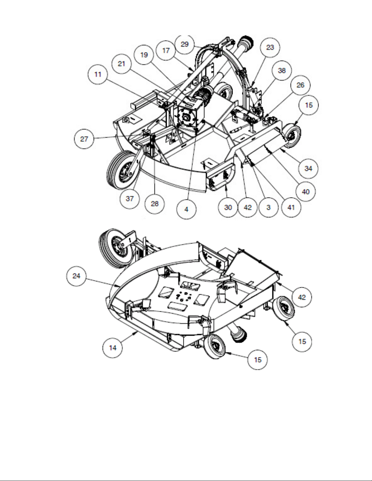
S08400 LXSP 5 SOIL PROFILER BODY COMPLETE
REVISION A FROM 012/2014
REF NO PART NO QTY DESCRIPTION
1 S08428-1 1 TOWER ASSEMBLY
2 S03546 1 HEX BOLT 5/8 UNC X 5 ½” LONG
3 S01025 3 HEX NUT 3/8 UNC
4 S03389 4 HEX BOLT ¾ UNF X 2 ¼” LONG
5 S04245 4 SPRING WASHER 3/4”
6 S05629 8 SKID TAB
7 S08432 1 CASTOR BEAM AND WHEEL ASSEMBLY
8 S03581 1 HEX BOLT 1” UNC X 5” LONG
9 MI00034-1 1 DECAL “SUPERIOR” (BIG)
10 ST07282 1 SERIAL NUMBER PLATE
11 S01039 3 NYLOC NUT 1 UNC
12 S08436 1 PROFILING HEAD ASSEMBLY
13 S08471 1 GEARBOX ASSEMBLY
14 S04370 1 ADJUSTABLE SKID WITH 30” HOLE CENTRE
15 S08431 2 FRONT WHEEL ASSEMBLY COMPLETE
16 S04133 3 CAT 1 TOP LINK PIN ¾ DIA
17 S08429 1 STAY BAR ASSEMBLY
18 S03545 1 HEX BOLT 5/8 UNC X 5” LONG
19 MI00034-6 1 DECAL “ROTATING DRIVELINE”
20 S01804 3 HEAVY FLAT WASHER 1”
21 MI00034-2 1 DECAL “CHECK OIL LEVEL”
22 S03539 8 HEX BOLT 5/8 UNC X 2 ½” LONG
23 S08406 1 HYD CYLINDER 6” STROKE 1 ½” BORE
24 S08420 1 SOIL PROFILER BODY FABRICATION
25 S08426 1 SAFETY LEG ASSEMBLY
26 S08422 1 CONTROL FLAP PIN
27 S03544 1 BOLT UNC 5/8 UNC X 4 ½” LONG
28 S01033 11 NYLOC NUT 5/8 UNC
29 S02262 2 HEX HD BOLT 1” UNC X 4” LONG
30 S08425 1 ADJUSTABLE SKID SHORT
31 S04011 3 LYNCH PIN
33 S07222 1 DRIVESHAFT COMPLETE 8 SERIES
34 MI00034-3 1 DECAL “KEEP CLEAR OPEN DISCHARGE”
35 S08423 1 CONTROL FLAP EXTENSION
36 MI00034-13 3 DECAL “MANUFACTURED BY”
37 S04225 4 WASHER 5/8”
38 S08405 10 HYDRAULIC CYLINDER 4” STROKE
39 S09087 1 CLUTCH ASSEMBLY
40 S03478 3 HEX BOLT 3/8 UNC X 1” LONG
41 S04242 3 SPRING WASHER 3/8”
42 S08416 1 CHUTE FLAT WELDMENT
43 ST02220 2 SHORT SKID LEG
S07497 1 CAT II TOWER TOP LINK CHAIN

19
PROFILING HEAD ASSEMBLY
S08436 PROFILING HEAD ASSEMBLY COMPLETE
REVISION B FROM 08/2012
REF NO PART
NO QTY DESCRIPTION
1 S05067 20 NYLOC NUT ¾” UNC
2 ST02471 4 CHANNEL STIFFENER
3 S08412 4 CUTTING BLADE
4 S08410 4 U- CHANNEL 125 X 65 PFC
5 S08414 4 PROFILED GUSSET
6 S08413 4 SWEEPING BLADE
7 S04055 20 HEX BOLT ¾ UNC X 2 ½” LONG
8 S08415 4 PLAIN GUSSET
9 S08403-4 1 PROFILING HEAD PLATE
10 ST02473 4 CHANNEL STIFFENER
11 ST02472 4 STIFFENER

20
GEARBOX ASSEMBLY
S08471 S300 GEARBOX ASSEMBLY COMPLETE
REVISION D FROM 04/2015
REF NO PART
NO QTY DESCRIPTION
1 S01003 18 NYLOC NUT ½” UNF
2 S01005-1 1 PINION 1:35 17 TEETH
3 S01005-2 1 GEAR 1:35 23 TEETH
4 S01007 1 1 ¼” UNF THIN NYLOC NUT
5 S01008 1 WASHER 1 ¼” X T6
6 S01010 2 SINGLE ROW TPR BEARING
7 S01015 2 SEAL INNER
8 S01016 2 SHAFT KEY
9 S01018 1 BREATHER/FILLER PLUG

21
10 S01019 1 GRASS RING
11 S02003 2 END CAP
12 S02008-A 1 CROSS SHAFT 1 ¾” X 20 X 16” REV
13 S02657 1 INNER BEARING
14 S03002 1 GEARBOX HOUSING
15 S04085 1 GREASE NIPPLE
16 S08462 1 OUTPUT SHAFT EXTRA HEAVY DUTY
17 S08467 1 HEAVY DUTY OUTPUT CARTRIDGE
18 S08469 1 SINGLE ROW BEARING
19 S08470 1 OUTER SEAL
20 S09666 1 INNER SEAL

22
CLUTCH ASSEMBLY
S09087 CLUTCH ASSEMBLY COMPLETE
REVISION B FROM 02/2015
REF NO PART
NO QTY DESCRIPTION
1 S04224 8 WASHER ½” X 1.5
2 S06401 1 SLIDING SPACER 1 ¾ X 20
3 S04026-1 2 FRONT PLATE
4 S03230 2 HEX BOLT 5/8” X 3 ½” UNC
5 S01033 2 NYLOC NUT 5/8”
6 S04103 1 BUSH
7 S02334 8 WHIT NUT ½”
8 S04100 8 CLUTCH SPRING
9 S02334 8 WHIT BOLT ½” X 5
10 S02317 1 BACK PLATE 1 ¾ X 20
11 S06400 1 DRIVE PLATE 1 ¾ X 20
12 S04027 4 FRICTION LININGS

23
FRONT WHEEL ASSEMBLY
S08431 FRONT WHEEL ASSEMBLY COMPLETE
REVISION A FROM 08/2015
REF NO PART
NO QTY DESCRIPTION
1 S02150 1 HUB 4 STUD
2 S02215 1 12” STEEL WHEEL ASSEMBLY
3 S02223 1 TAPERED BEARING & SEAL
4
5 S02225 4 HEX NUT 7/16 UNF
6 S02229 1 BEARING TAPERED LM11949-10
7 S02231 1 HEX SLOTTED NUT 3/4UNF
8 S02232 1 DUST CAP
9 S02233 1 SPLIT PIN
10 S02237 4 WHEEL HUB STUD 7/16 UNF
11 S04226 1 WASHER FLAT BRIGHT ¾ X 3MM
12 S08434 1 STUB AXLE ADJ BRACKET ASSEMBLY

24
CASTOR WHEEL ASSEMBLY
S08432 CASTOR WHEEL ASSEMBLY COMPLETE
REVISION A FROM 09/2015
REF NO PART
NO QTY DESCRIPTION
1 S02223 1 TAPERED BEARING & SEAL
2 S02224 1 HUB 5 STUD
3 S02225 5 HEX NUT 7/16 UNF
4 S02229 1 BEARING TAPERED LM11949-10
5 S02231 1 HEX SLOTTED NUT 3/4/16 UNF
6 S02232 1 DUST CAP
7 S02233 1 SPLIT PIN
8 S02237 5 WHEEL HUB STUD 7/16 UNF
9 S04085 1 GREASE NIPPLE
10 S04226 1 WASHER FLAT BRIGHT ¾” X 3MM
11 S04269-1 1 MONOFIL CASTOR WHEEL 520X10
12 S08435 1 CASTOR BEAM ASSEMBLY

25

26
Manufactures:- front mount mowers, finishing mowers, roller mowers, slashers, orchard slashers,
vineyard mowers, vee type slashers, wide slashers 10 meter, belt drive & gear drive pasture
toppers, post hole diggers, grader blades, turf aerators, lifting jibs.
INSTALLATION
DEALER / DEALER REPRESENTATIVE TO (tick) EACH ITEM
( ) Visual check of machine
( ) All fluid levels & Grease points
( ) Operating functions
SAFE OPERATING INSTRUCTIONS
( ) Function of controls
( ) starting & stopping procedures
( ) Proper use & operation of equipment
( ) Instruction on safe operation
( ) Follow all “Safe Operation” guidelines set out in operators manual and equipment decals.
( ) Read operators manual before operating
( ) Check that all safety covers & shields are in place
( ) It is the owners’ responsibility to provide operator’s manuals & to ensure that all operators
read these manuals prior to operation.
PROPER MAINTENANCE OPERATION
( ) Periodical maintenance & inspection
( ) Preventive maintenance
( ) Use of proper lubricants
( ) Lubrication using lubrication chart where provided
( ) Precautions for proper adjustments
AFTER SALES SERVICE INSTRUCTION
( ) Warranty & service policy
( ) Periodic service schedule
( ) Spare parts ordering procedure
EQUIPMENT MODEL: SERIAL No
OPTIONAL EQUIPMENT
WHERE FITTED
( ) Equipment has been installed to manufacturers’ specifications, operator manual and
technical bulletins.
INSTALLED BY: (print)
PURCHASER
WARRANTY
31 ANTIMONY STREET
CAROLE PARK QLD 4076
Ph: 07 3271 3177
Fax: 07 3271 3285

27
Superior guarantees all new equipment (manufactured by Superior) against faulty parts and or
workmanship for a period of Six (6) months or 180 days from date of purchase. Any variation to
this figure will be provided in writing. The use of non-original or non-Superior approved parts during
the warranty period may invalidate this warranty. During this warranty period Superior agrees to
replace pro-rata, the parts proved faulty by our evaluation team.
Please note: PTO Shafts, Bearings, and Vee Belts, hydraulic pumps, motors and fittings are
excluded and are to be covered by the original equipment manufacturers guarantee.
Any part used for cutting or digging (blades, blade carriers, auger teeth or pilots) will be subject to
testing and evaluation to determine any claim justifications. Superior has their own Warranty Claim
Form that is to be completed in full before any action is taken.
Any equipment or part thereof which is subject to a warranty claim must be shipped by prepaid
freight or delivered to Superior Equipment in Brisbane for evaluation. Alternatively, the item/s may
be delivered by prepaid freight to an Approved Superior Service Centre to evaluation. Superior will
not pay for any service or repair work carried out without prior, written approval. Note – Superior’s
Labour Rate for External Repairs will apply to all work authorised under this Warranty.
PLEASE SIGN & RETURN FOR REGISTRATION WITHIN 14 DAYS OF PURCHASE TO
VALIDATE THE WARRANTY
MACHINE MODEL NO: ______________________________________________________
SERIAL NO: ______________________________________________________
DATE PURCHASED (END USER) ______________________________________________
ADDRESS __________________________________________________________________
SIGNATURE___________________________________PHONE_______________________
AGENT OR DEALER STAMP
____________________________________________________________________________
WARRANTY IS QUOTED AT 180 DAYS AGAINST FAULTY PARTS & WORKMANSHIP
FROM DATE OF SALE TO END USER.
PLEASE NOTE: UNDER DUTY OF CARE STIPULATIONS, IT IS A REQUIREMENT THAT THE
PURCHASER IS FULLY INSTRUCTED IN THE USE OF THESE GOODS. THIS WARRANTY
FORM CANNOT BE ACCEPTED UNLESS IT IS SIGNED & FULLY COMPLETED ON BOTH
SIDES.
____________________________________________________________________________
This manual suits for next models
1
Table of contents
Other Alamo Farm Equipment manuals