burchland GSX 100 User manual

DRIVE OVER GRAIN HOPPER
BURCHLAND
GSX 100 / 130GSX 100 / 130
OPERATORS MANUAL

Table Of Contents

Introduction
BURCHLAND
GSXGSX DRIVE OVER HOPPERS

BURCHLAND
2Burchland Mfg
Table Of Contents
Safety Instructions .............................................................................................. 4
Signal Words ...............................................................................................................4
General Safety Instructions .........................................................................................5
Start-Up Safety ............................................................................................................5
Operation Safety..........................................................................................................5
Transport Safety ..........................................................................................................6
Storage Safety.............................................................................................................6
Service and Maintenance Safety.................................................................................6
Hydraulic Safety ..........................................................................................................7
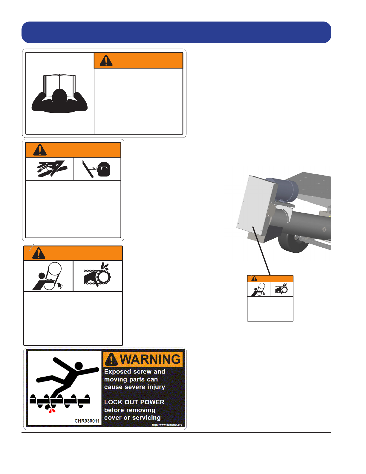
Safety Decals ..............................................................................................................7
Decal Installation ......................................................................................................7-8
Safety Decal Placement ..............................................................................................9
Operation Instructions...................................................................................... 10
Hydraulic System Requirements ...............................................................................10
Electric System Requirements ..................................................................................10
Preparing the Machine for Operation from Transport Mode (Manual Lift) ............10-12
Preparing the Machine for Operation from Transport Mode (Hydraulic Lift).........12-13
Unloading ..................................................................................................................14
Starting (Hydraulic Drive Models)..............................................................................15
Starting (Electric Drive Models) .................................................................................15
Shutdown...................................................................................................................16
Preparing the Machine for Transport from Operation Mode .................................16-18
Cleanout ....................................................................................................................19
Storage ......................................................................................................................20
Maintenance Instructions .............................................................................................21
Lubrication .................................................................................................................21
Servicing the Drive Chains ........................................................................................22
Wheel Bearings .........................................................................................................22
Wheel Nut Torque......................................................................................................22
U-Joint and Sprocket Set Screws..............................................................................22
Mounting Bolts and Hardware ...................................................................................23
Warranty ............................................................................................................. 24
Warranty Registration Card .......................................................................................25

BURCHLAND
3
Drive Over Hopper
Introduction
Parts Book.......................................................................................................... 27
GSX 100/130 Frame and Guard Assembly ..........................................................30-31
GSX Ramp Assembly ................................................................................................32
GSX 100/130 Auger Drive Assembly.........................................................................33
GSX 100/130 Junction Box Assembly ..................................................................34-37
GSX 130 Discharge Auger Assembly ........................................................................38
GSX 100 Discharge Auger Assembly ........................................................................39
GSX 100/130 Transport Assembly .......................................................................40-41
GSX Hitch Assembly .................................................................................................42
GSX 100/130 Hydraulic Drive Assembly ...................................................................43
GSX 100/130 Electric Drive Assembly .................................................................44-45
GSX Hydraulic Lift Assembly................................................................................46-47
GSX Side Chute Assembly........................................................................................48
GSX Auger Stand Assemblies ..............................................................................49-51

BURCHLAND
4Burchland Mfg
The Safety Alert symbol to the left identies important safety messages on the product
and in the manual. When you see this symbol, be alert to the possibility of personal injury
or death. Follow the instructions in the safety messages.
DANGER
Indicates an imminently hazardous situa-
tion that, if not avoided, will result in seri-
ous injury or death.
WARNING
Indicates a hazardous situation that, if not
avoided, could result in serious injury or
death.
CAUTION
Indicates a hazardous situation that, if not
avoided, may result in minor or moderate
injury.
NOTICE
Indicates a potentially hazardous situation that, if not
avoided, may result in property damage.
Signal Words
Note the use of the signal words DANGER, WARNING, CAUTION, and NOTICE with the safety messages.
The appropriate signal word for each message has been selected using the denitions below as a guideline.
The Safety Alert symbol means ATTENTION, BE ALERT!, YOUR SAFETY IS INVOLVED.
Safety

BURCHLAND
5
Drive Over Hopper
General Safety Instructions
• Have a rst-aid kit available for use and know how to use it.
• Have a re extinguisher available, stored in a highly visible location, and know how to use it.
• Wear appropriate protective gear. This list may include but is not limited to:
-- hard hat
-- protective shoes with slip resistant soles
-- protective glasses or goggles
-- heavy gloves
-- wet weather gear
-- hearing protection
-- respirator or lter mask
• Read and understand the Operator’s Manual and all safety
signs before operating, servicing, adjusting, repairing, or unplugging the equipment.
• Do not attempt any unauthorized modications to your Burchland product as this could aect
function or safety, and could aect the life of the equipment.
• Inspect and clean the working area before operating.
• Keep hands, feet, clothing, and hair away from moving parts.
• Ensure bystanders are clear of the area before operating.
Start-Up Safety
• Do not let inexperienced operators or children run this equipment.
• Place all tractor and machine controls in neutral before starting.
• Operate only with ROPS and seatbelt equipped tractors.
• Do not operate inside a building unless there is adequate ventilation.
• Ensure all shields are in place and in good condition before operating.
• Stay clear of PTO shaft on auger and machine when engaging PTO.
• Keep clear of the auger when raising for transport or lowering for operation.
• Inspect the machine carefully each day by walking around it before starting operation.
Operation Safety
• Do not permit riders.
• Do not wear loose tting clothing during operation.
• Do not allow anyone other than the operator close to the auger hopper when in operation.
• Never stand near the hopper while raising or lowering.
• Have another person nearby who can shut down the equipment in case of accident.
• Do not operate with any of the safety guards removed.
• Keep body, hair, and clothing away from moving parts. Stay away from intake during operation.
Safety

BURCHLAND
6Burchland Mfg
Transport Safety
• Check with local authorities regarding transport on public roads. Obey all applicable laws and regulations.
• Always travel at a safe speed. Consult local authorities for further details. Use cautions when turning cor-
ners or meeting trac.
• Use extreme care and minimum ground speed when operating or transporting on hillsides, over rough
ground, or near ditches or fences.
• Make sure the SMV (slow moving vehicle) emblem and all the lights and reectors that are required by lo-
cal authorities are in place, are clean, and can be seen by all trac.
• Do not allow riders on the equipment or towing vehicle during transport.
• Stay away from overhead obstructions and power lines when operating and transporting. Electrocution can
occur without direct contact.
• Ensure that tires are inated to the manufacturer’s recommended pressure.
Storage Safety
• Store the unit in an area away from human activity.
• Do not permit children to play on or around the stored machine.
• Block the wheels of the hopper so that it will not move and tear the jack from it’s mount.
Service and Maintenance Safety
• Stop engine, set brake, remove ignition key, and wait for all moving parts to stop before servicing, adjust-
ing, repairing, or unplugging.
• Support the equipment with blocks or safety stands before working beneath it.
• Follow good shop practices including:
-- keep service area clean and dry
-- be sure electrical outlets and tools are properly grounded
-- use adequate light for the job.
• Use only tools, jacks, and hoists of sucient capacity for the job.
• Replace and secure all shields removed during servicing before operating.
• Use heavy leather gloves to handle sharp objects.
• Check hydraulics regularly for leaks. Use cardboard to look for leaks, and use hand and eye protection.
• Relieve pressure on hydraulic system before repairing or adjusting.
• Failure to follow proper procedures when mounting a tire on a wheel or rim can produce an explosion,
which may result in serious injury or death.
Safety

BURCHLAND
7
Drive Over Hopper
Hydraulic Safety
• Always place all hydraulic controls in neutral and relieve system pressure before disconnecting or working
on hydraulic system.
• Keep all components in the hydraulic system tightly secured and in good condition and clean.
• Replace any worn, cut, abraded, attened, or crimped hoses.
• Do not attempt any makeshift repairs to the hydraulic ttings or hoses with tape, clamps, or concrete. The
hydraulic system operates under extremely high pressure; such repairs will fail suddenly and create a haz-
ardous and unsafe condition.
Avoid High-Pressure Fluids
This machine uses a high-pressure hydraulic system. Escaping uid under
pressure can penetrate the skin causing serious injury. Never search for
leaks with your hands. Protect hands. Use a piece of cardboard to nd
location of escaping uid. Stop engine and relieve pressure before discon-
necting lines or working on hydraulic system.
If hydraulic uid penetrates your skin, see a doctor immediately.
Injected uid must be removed surgically within hours or gan-
grene may result. Contact a knowledgeable medical source or call
911.
Safety Decals
• Keep safety decals clean and legible at all times.
• Replace safety decals that are missing or have become illegible. See decal location gures below.
• Replaced parts must display the same decal(s) as the original part.
• Safety decals are available from your dealer or by calling the factory at 641-498-2063.
Decal Installation
• To install safety signs, ensure the installation area is clean and dry. Decide on the exact position before
you remove the backing paper. Remove the smallest portion of the split backing paper and align over the
specied area. Carefully press in place.
• Slowly peel back the remaining paper and smooth the remaining portion in place. Small air pockets can be
pierced with a pin and smoothed out.
Safety

BURCHLAND
8Burchland Mfg
To prevent serious injury or death:
Relieve pressure on system before
repairing or adjusting or disconnecting.
Wear proper hand and eye protection
when searching for leaks. Use wood or
cardboard instead of hands.
Keep all components in good repair.
•
•
•
HIGH-PRESSURE FLUID HAZARD
WARNING
700
WARNING
To Prevent Serious Injury or Death
• Avoid unsafe operation or
maintenance.
• Do not operate or work on this
machine without reading and
understanding the operator’s
manual.
• If manual is lost, contact your
nearest dealer for a new manual.
1
Safety Decals
Part # 11187
1 Required
Part # 11190
1 Required
Part # 12081
2 Required
3 on electric drive models
Part #12740
4 Required
Electric Drive
Decal Placement
404
• Close and secure guards and shields before
starting.
• Keep hands, feet, hair and clothing away from
moving parts.
• Disconnect and lockout power source before
adjusting or servicing.
• Do not stand or climb on machine when
operating.
MOVING PART HAZARD
WARNING
To prevent serious injury or death from
moving parts:
.125" Corner Radius Finished Edge
P/N: 404
Size: as shown
Qty.: 500
Colours: Munsell Orange and Black,
Printed on White material.
*Clear overlaminate is to be applied.*
BACKSLIT - UNSPECIFED.
Munsell Orange
4.00"
4.00"
Safety
404
• Close and secure guards and shields before
starting.
• Keep hands, feet, hair and clothing away from
moving parts.
• Disconnect and lockout power source before
adjusting or servicing.
• Do not stand or climb on machine when
operating.
MOVING PART HAZARD
WARNING
To prevent serious injury or death from
moving parts:
.125" Corner Radius Finished Edge
P/N: 404
Size: as shown
Qty.: 500
Colours: Munsell Orange and Black,
Printed on White material.
*Clear overlaminate is to be applied.*
BACKSLIT - UNSPECIFED.
Munsell Orange
4.00"
4.00"

BURCHLAND
9
Drive Over Hopper
WARNING
To Prevent Serious Injury or Death
• Avoid unsafe operation or
maintenance.
• Do not operate or work on this
machine without reading and
understanding the operator’s
manual.
• If manual is lost, contact your
nearest dealer for a new manual.
1
One of decal # 12740 on
inside and outside of cover.
Also, place here on optional
side chute cover.
Two of decal # 12740
required in the hopper.
One on each side.
Place decal # 12081 on
the bottom side of the
roller chain access door.
Safety Decal Placement
404
• Close and secure guards and shields before
starting.
• Keep hands, feet, hair and clothing away from
moving parts.
• Disconnect and lockout power source before
adjusting or servicing.
• Do not stand or climb on machine when
operating.
MOVING PART HAZARD
WARNING
To prevent serious injury or death from
moving parts:
.125" Corner Radius Finished Edge
P/N: 404
Size: as shown
Qty.: 500
Colours: Munsell Orange and Black,
Printed on White material.
*Clear overlaminate is to be applied.*
BACKSLIT - UNSPECIFED.
Munsell Orange
4.00"
4.00"
Safety
To prevent serious injury or death:
Relieve pressure on system before
repairing or adjusting or disconnecting.
Wear proper hand and eye protection
when searching for leaks. Use wood or
cardboard instead of hands.
Keep all components in good repair.
•
•
•
HIGH-PRESSURE FLUID HAZARD
WARNING
700
404
• Close and secure guards and shields before
starting.
• Keep hands, feet, hair and clothing away from
moving parts.
• Disconnect and lockout power source before
adjusting or servicing.
• Do not stand or climb on machine when
operating.
MOVING PART HAZARD
WARNING
To prevent serious injury or death from
moving parts:
.125" Corner Radius Finished Edge
P/N: 404
Size: as shown
Qty.: 500
Colours: Munsell Orange and Black,
Printed on White material.
*Clear overlaminate is to be applied.*
BACKSLIT - UNSPECIFED.
Munsell Orange
4.00"
4.00"

BURCHLAND
10 Burchland Mfg
EQUIPMENT MATCHING
Hydraulic System Requirements
In order to operate the hydraulic drive motor, the tractor hydraulic system must be capable of 15 gpm (56.8
L/min) at 1200 psi (8273 kPa) for the GSX-100 (10”) hopper, and 15 gpm (56.8 L/min) at 1800 psi (12,411
kPa) for the GSX-130 (13”) hopper. Use caution routing the hoses from the drive over hopper to the tractor.
Ensure that they are not a tripping hazard and that they can’t become tangled in the auger or PTO drive.
Electric System Requirements
A minimum 10 hp (7.35 Kw) electric motor (1725-1750 rpm) is required to power the GSX-100 (10”) hopper,
and a minimum 15 hp (11.03 Kw) electric motor (1725-1750 rpm) is required to power the GSX-130 (13”)
hopper. Ensure the power source has adequate amperage at the proper voltage. Have a licensed electri-
cian provide power and install weatherproof control switches in a safe and convenient location for the opera-
tor. All power cords should be protected and secured during operation. When purchasing an electric drive
hopper, the customer is responsible for supplying the electric motor, all wiring and controls.
Preparing the machine for operation from transport mode.
(Manual lift models)
NOTICE
Locate the machine on reasonably at and rm ground,
free from obstructions. Placement on uneven or soft
ground may cause excessive loads on the machine or
clearance issues. Corresponding damage to the ma-
chine or transport vehicle could result.
1. Use the towing vehicle to back the drive over
hopper into place. The discharge spout of the hopper
should be over the intake grate of the auger you plan
to use. Make sure there is a straight line path for the
grain truck to drive over the ramps of the hopper.
2. The supplied jack comes with an upper and
lower mounting tube. The lower mount is used when
placing the jack on the hitch end of the machine. The
upper mount is used when placing the jack on the dis-
charge end of the machine.
3. Unhook the towing vehicle and use the sup-
plied jack to lower the hitch end of the machine to the
ground. Once lowered to the ground, the hitch can be
removed if necessary.
Upper mount for
discharge tube.
Lower mount
for hitch.
Operation
Manual lift jack

BURCHLAND
11
Drive Over Hopper
Preparing the machine for operation from transport mode.
(Manual lift models) continued.
Hitch end of the machine lowered to the ground.
4. Remove the jack from the hitch end of the
hopper and take it to the discharge end of the ma-
chine.
5. Lower the jack support bar to the ground by
removing the support bar keeper pin. Rotate the lock
bracket to the side and the jack support bar can be
dropped to the ground.
Remove support
bar keeper pin.
Rotate lock bracket to the side
to lower the jack support bar.
Jack support bar
6. Mount the jack on the square jack mount lug
on the side of the discharge auger tube. Lower the
jack down until it is pushing on the jack support bar.
Keep cranking the jack to remove weight from the
transport lock pins.
7. Once there is no weight on the transport lock
pins, pull one pin on each side of the hopper. Now
use the jack to lower the hopper to the ground. The
transport wheels will pivot up as the hopper frame is
lowered. Once the hopper frame is on the ground,
the jack can remain on the discharge auger during
operation.
Remove transport lock pins
once weight is removed.
Operation

BURCHLAND
12 Burchland Mfg
Preparing the machine for operation from transport mode.
(Manual lift models) continued.
8. Un-hook the ramp lock chains and manually lower the ramps to the ground by holding on to the ramp
handle and pulling the top of the ramp away from the hopper.
CAUTION – KEEP YOURSELF AND ANY BYSTANDERS AWAY FROM THE
RAMPS AS THEY ARE BEING LOWERED TO THE GROUND.
Preparing the machine for operation from transport mode.
(Hydraulic lift models)
See steps 1-3 above under “Preparing the machine for operation from transport mode (Manual lift models)”.
Steps 1-3 are also used on the hydraulic lift models to lower the hitch end of the hopper to the ground.
NOTICE
Foreign material can severely damage hydraulic
components. Clean any dirt or debris from the hose
ends and hydraulic system couplers with a clean rag or
paper towel before connecting.
WARNING
Always turn o the tractor engine before
connecting any hoses to the tractor hy-
draulic valve couplers.
WARNING
Damaged hydraulic hoses can fail sudden-
ly causing unexpected machine movement
that can result in serious injury or death.
• Route hydraulic hoses to prevent pinch-
ing, rubbing, or binding.
• Keep the hoses away from moving parts.
• Secure the hoses to the machine to pre-
vent dragging while transporting.
• Cover or protect the hoses from damage
during operation.
• Repair or replace damaged hoses.
Operation

BURCHLAND
13
Drive Over Hopper
4. Hook up the hydraulic lift cylinders’ power sup-
ply hoses to a hydraulic valve on a tractor. Make sure
the tractor is not running when the hoses are hooked
up.
Preparing the machine for operation from transport mode.
(Hydraulic lift models) continued.
Lift cylinders’ power
supply hoses
7. With the tractor running, engage they hydrau-
lic control valve to lift the drive over hopper slightly
and remove the weight from the transport lock pins.
8. Remove the transport lock pins and set them
aside.
9. Use the tractor’s hydraulic control valve to
lower the discharge end of the drive over hopper to
the ground.
10. Shut o the tractor engine and disconnect the
lift cylinders’ power supply hoses.
11. Connect the auger power supply hoses.
12. Un-hook the ramp lock chains and manually
lower the ramps to the ground by holding on to the
ramp handle and pulling the top of the ramp away
from the hopper.
Remove transport lock pins
once weight is removed.
Operation
CAUTION – KEEP YOURSELF AND ANY BYSTANDERS AWAY FROM THE
RAMPS AS THEY ARE BEING LOWERED TO THE GROUND.
Auger
power
supply
hoses

BURCHLAND
14 Burchland Mfg
OPERATION - UNLOADING
NOTICE
Align the tires of the haul vehicle with the ramps of the
drive over hopper. Driving outside the ramp area may
cause severe damage to the drive over hopper.
1. Set up the machine per instructions in the section above (Preparing machine for operation from transport
mode).
2. Position the haul vehicle for unloading. Ensure the tires are aligned with the safe drive-over zone. See
the gure below for the safe drive-over zone.
HAUL VEHICLE
Drive-over safe zone is in
the x’d out areas.
Never drive over the center
dump area of the hopper.
Severe damage may occur.
3. Drive the haul vehicle over the hopper.
4. Align the vehicle’s grain discharge with the intake area of the drive over hopper.
5. Start the hopper according to the instructions listed below under “Starting”.
6. Begin unloading grain into the hopper.
Operation

BURCHLAND
15
Drive Over Hopper
OPERATION - STARTING
Hydraulic Models
1. Place all tractor and hydraulic controls in neutral.
2. Start the tractor and run the engine at idle speed.
3. Place the tractor hydraulic control in a detent or continuously on position.
Important - Make sure the augers are turning the correct direction to move grain from the hopper
intake area to the discharge spout. When standing near the discharge end of the machine and look-
ing at the intake hopper, the augers should be turning clockwise.
4. Increase engine speed and adjust hydraulic owrate on the tractor to achieve the desired augering speed.
Electric Models
1. Place the control switch (customer supplied) in the on position.
Operation

BURCHLAND
16 Burchland Mfg
OPERATION - SHUTDOWN
Hydraulic Models
1. Run the machine until the center hopper and discharge tube are empty.
2. Adjust the tractor engine speed to idle.
3. Place tractor hydraulic controls in neutral.
4. Shut o the tractor engine.
Electric Models
1. Run the machine until the center hopper and discharge tube are empty.
2. Turn the motor control switch (customer supplied) o.
Preparing the machine for transport from operation mode.
WARNING
NOTICE
Empty the auger before transporting.
Transporting a full auger will place excessive loads on
the discharge tube assembly, frame, axle assembly,
hitch, and towing unit.
Operation
Before continuing, please reread the safe-
ty information relevant to this section at
the beginning of this manual. Failure to
follow the safety instructions can result in
serious injury, death, or property damage.

BURCHLAND
17
Drive Over Hopper
To reduce the risk of injury or death to people using this equipment, follow basic safety precautions when
transporting.
1. Make sure that all lights and reectors required by the local highway and transport authorities are in place,
are functioning, and can be seen clearly by all overtaking and oncoming trac.
2. Be sure the unit is hitched securely to the towing vehicle.
3. Use hazard-warning ashers when transporting with a tractor unless prohibited.
4. Keep to the right and yield the right-of-way to allow faster trac to pass.
5. Take special care and precautions when transporting during times of limited visibility such as rain, snow,
fog, dusk, or at night. It is recommended that you wait for a more appropriate time to move.
6. DO NOT transport faster than 20 mph unless GVWR is more than 7000 lb. Never exceed 40 mph.
Preparing the machine for transport from operation mode. - Continued
Transport Safety
Preparing the machine for transport from operation mode. - Continued
1. Check the wheel nut torque prior to transporting the unit. See the maintenance section for recommended
torque values.
2. Check that the tires are inated to the manufacturer’s recommended pressure prior to transporting the
unit.
3. Fold up the ramps and use the supplied chains and hooks to lock the ramps together in an upright posi-
tion.
CAUTION – KEEP YOURSELF AND ANY BYSTANDERS AWAY
FROM THE RAMPS AS THEY ARE BEING RAISED AND LOCKED.
4. Raise the discharge end of the hopper. See the “Preparing machine for operation from transport mode”
earlier in this manual.
5. Raise the hitch end of the hopper until the height of the hitch matches the connecting hitch on the tow
vehicle. See the “Preparing machine for operation from transport mode” earlier in this manual.
Operation

BURCHLAND
18 Burchland Mfg
Preparing the machine for transport from operation mode. - Continued
6. Disconnect the hopper from the hydraulic source or disconnect the electric supply cord on electric drive
models.
NOTICE
Secure hydraulic hoses or electric power cord on elec-
tric drive models to the machine to prevent damage
from dragging while transporting.
7. Secure hydraulic lines or any power cords to the machine before transporting.
8. Connect the tow vehicle to the drive over hopper and use a retainer to lock the hitch pin in place.
CAUTION
Always use transport chains when trans-
porting implements.
Failure to use chains could cause person-
al injury or damage if implements become
disengaged.
9. Install transport safety chains (customer supplied) between the tongue of the drive over hopper and
the frame of the tow vehicle. Transport chains should have a minimum rating equal to the gross weight of
implement and all attachments. Allow no more slack in chains than necessary to permit turning. Replace
transport chains if any link or end tting is broken, stretched, or damaged. DO NOT WELD TRANSPORT
CHAINS.
10. Crank the jack up fully and stow the jack on a square jack mount lug on the hitch or on the discharge
tube.
Operation
This manual suits for next models
1
Table of contents
Other burchland Farm Equipment manuals
Popular Farm Equipment manuals by other brands

OREC
OREC RABBIT RM60W instruction manual

McFarlane
McFarlane HDL-1100 Series Operator's manual and parts list

Degelman
Degelman M28 Operator's & parts manual

Farmet
Farmet DUOLENT DX 380 NS operating manual

Förster-Technik
Förster-Technik CalfRail quick start guide

Wiesenfield
Wiesenfield WIHE-03201 user manual