Alamo John Deere 6215 Installation guide

© 2004 Alamo Group Inc.
ALAMO INDUSTRIAL
1502 E. Walnut
Seguin, Texas 78155
830-379-1480
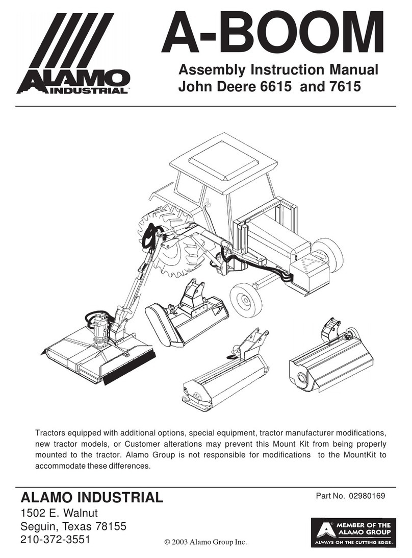
Assembly Instruction Manual
John Deere 6215, 6320, 6415,6420
PartNo.02980007
Tractors equipped with additional options, special equipment, tractor manufacturer modifications,
new tractor models, or Customer alterations may prevent this Mount Kit from being properly
mounted to the tractor. Alamo Group is not responsible for modifications to the MountKit to
accommodatethesedifferences.
Published10/04


TOTHEOWNER/OPERATOR/DEALER
All implements with moving parts are potentially hazardous. There is no substitute for a
cautious, safe-minded operator who recognizes the potential hazards and follows reasonable
safety practices. The manufacturer has designed this implement to be used with all its safety
equipment properly attached to minimize the chance of accidents.BEFORE YOU START!!
Read the safety messages on the implement and shown in your manual. Observe the rules
of safety and common sense!
WARRANTYINFORMATION:
Read and understand the complete Warranty Statement found in this Manual. Fill out the
WarrantyRegistration Formin fulland returnit within30 Days. Makecertain theSerial Number
oftheMachine isrecordedonthe WarrantyCardand ontheWarrantyForm thatyouretain. The
use of "will-fit" parts will void your warranty and can cause catastrophic failure with possible
injury or death.

©2004 Alamo Group Inc. Index-3
Machete (JD -62,63,6420 Asy Man) 10/04
INTRODUCTION
ABOUT THIS MANUAL:
Theintentofthispublicationtoprovidethecompetenttechnicianwiththeinformationnecessary
to perform the CORRECT Assembly to the Alamo Industrial Product. This will, in turn provide for
complete customer satisfaction
ItishopedthattheinformationcontainedinthisandotherManualswillprovideenoughdetailto
eliminate the need for contact of the Alamo Industrial Technical Service Dept. However, it should be
understood that many instances may arrive where correspondence with the Manufacturer is neces-
sary.
CONTACTING MANUFACTURER: (Please help us Help You! Before You Call! )
Alamo Industrial Service Staff Members are dedicated to helping you solve your problem, or
your customer’s service problem as quickly and efficiently as possible. Unfortunately, we receive
entirely to many calls with only a minimum amount of information. In some cases, the correspondent
hasnevergoneouttolookattheequipmentandmerelycallsinquiringoftheproblemsdescribedtohim
by the operator or customer.
Most calls received by Alamo Industrial Service can be classified into approx. 6 general categories.
1. Hydraulicor MechanicalTrouble Shooting.
2. Request for Technical Information or Specifications.
3. Mountingor Fitting Problem.
4. Special Service Problem.
5. Equipment Application Problems.
6. Tractor Problem Inquiries.
HOW YOU CAN HELP:
Makesure thecallis necessary! Mostof thecallsreceived maynot benecessaryif theDealer
Service Technician would do the following.
1. Check the Service Information at your Dealership provided by Alamo Industrial, This
wouldinclude,ServiceBulletins,InformationBulletins,PartsManuals,OperatorsManuals, Assembly
ManualorServiceManual,manyoftheseareavailableviatheAlamoIndustrialInternetsite(www.Alamo-
Industrial.Com). Attempt to diagnose or repair problem before calling.
2. IfacalltoAlamoIndustrialisneeded,CertainInformationshouldbeavailableandready
fortheAlamoIndustrialServiceStaff.Suchinformationas, MachineModel,SerialNumber,YourDealer
Name,YourAccountNumberandAnyotherinformationthatwillbeuseful. Thisinformationisvitalfor
the development of a prompt and correct solution to the problem. This will also help to develop a
databaseofproblemsandrelatedsolutions,whichwillexpediteasolutiontofutureproblemsofasimilar
nature. 3. The technician may be asked to provide detailed information about the problem
includingtheresultsofanyrequiredtroubleshootingtechniques.Iftheinformationisnotavailable,The
technician may be asked to get the information and call back. Most recommendations for repairs will
be based on the procedures listed in the Service Manual / Trouble Shooting Guide and Information
provided by customer.
CONTACT ALAMO INDUSTRIAL:
Alamo Industrial, 1502 E. Walnut St. Seguin TX. 78155, Technical Service Dept. PH: 830-372-2708

Machete (JD -62,63,6420 Asy Man) 10/04
©2004 Alamo Group Inc. Index-4
Page
Section 1
Pre-DiliveryCheckList...................................................................... 1-2 to 1-4
Section 2
Wheel Counter Weight Parts.............................................................2-2
WheelCounterWeightInstallation.................................................... 2-3
Section 3
FrontPumpDriveParts.....................................................................3-2
CrankshaftPulleyPreparation...........................................................3-3 to 3-5
PumpDriveshaftAssembly...............................................................3-5
PumpDriveshaftHalf, ShaftEnd.......................................................3-5
FrameRailSupportInstallation..........................................................3-6
HydraulicTankMountFrame.............................................................3-6
PumpMountPlate..............................................................................3-7
PumpDrive Shaft,TubeEnd.............................................................3-7
PumpInstallation................................................................................3-8 to 3-10
HydraulicTankInstallation................................................................. 3-10 to 3-11
FrontBumperInstallation...................................................................3-11
Section 4
FrameRail Pre-Assembly................................................................ 4-2 to 4-6
HighFrameParts...............................................................................4-7
FrameRailPre-Installation................................................................ 4-8 to 4-11
HighFramePre-Installation............................................................... 4-12 to 4-16
Tack Welding Frame Assembly........................................................ 4-17 to 4-21
Remove Frame for Final Welding......................................................4-21 to 4-23
Section 5
( Tractor S/N 398796 Dec. 2003 & Down see page 5-1 thru 5-10
TractorStackValveIntroduction........................................................5-2
RemoveStackValveEndPlate.........................................................5-3
Prepare Replacement Stack Valve End Plate...................................5-4 to 5-5
InstallReplacement StackValve End Plate.......................................5-5
InstallHoseFittingsinStackValve.................................................... 5-6
ConnectHosestoStack Valve..........................................................5-7 to 5-8
Connect Hoses from Stack Valve to Control Valve...........................5-9 to 5-10
( Tractor S/N 398797 Jan. 2004 & Up see page 5-11 thru 5-20
TractorStackValveIntroduction........................................................5-12
RemoveStackValveEndPlate.........................................................5-13
Prepare Replacement Stack Valve End Plate...................................5-14 to 5-15
InstallReplacement StackValve End Plate.......................................5-15
InstallHoseFittingsinStackValve.................................................... 5-16
ConnectHosestoStack Valve..........................................................5-17 to 5-18
Connect Hoses from Stack Valve to Control Valve...........................5-19 to 5-20
INDEX -ASSEMBLY INSTRUCTION

©2004 Alamo Group Inc. Index-5
Machete (JD -62,63,6420 Asy Man) 10/04
INDEX -ASSEMBLY INSTRUCTION
Page
Section 6
JoystickMountParts......................................................................... 6-2
InstallJoystickMounttoSeat............................................................ 6-3
Install Joystick Controler to Seat Bracket.......................................... 6-4
TractorFloorMatRemoval................................................................6-4
Wire Harness to Tractor Connections...............................................6-5 to 6-6
TractorIgnitionWireConnection....................................................... 6-6
Connect Wire Harness to Joystick....................................................6-6
TractorFloorMatre-Install.................................................................6-6
TractorCabDecalInstallation........................................................... 6-7
Connect Wire Harness to Control Valve........................................... 6-8 to 6-12
Section 7
FrameRailsFinalInstallation.............................................................7-2
BoomRestInstallation.......................................................................7-3
AxleStrapInstallation.........................................................................7-4
StabilizerKitInstallation.....................................................................7-4
HighFrameInstallation...................................................................... 7-5 to 7-8
Tie Up Hoses to Tractor Frame (Stack valve Hoses)....................... 7-8
LeftStep/ CounterWeight Installation.............................................. 7-9 to 7-11
Section 8
Pump / Tank Hose Connections to Machete Frame.........................8-2 to 8-3
Boom Hose Connections to Pump and Tank....................................8-3
SwingCylinderHoseConnections....................................................8-4
LiftCylindertoKingPostInstallation..................................................8-4
LiftCylinderHoseConnections......................................................... 8-5
HoseConnectionstoValve................................................................8-5
HoseConnectionSummary.............................................................. 8-6
Hose Specifications (Type and Torque)............................................ 8-7
ValvePortMarkings........................................................................... 8-8
ValveSpoolFunctions....................................................................... 8-8
Section 9
Boom,MounttoKingPost................................................................. 9-2 to 9-4
AttachLiftCylindertoBoom.............................................................. 9-2
BoomHoseConnections.................................................................. 9-3 to 9-4
FrontPumpCoverInstallations......................................................... 9-4
RotaryHeadInstallationtoBoom...................................................... 9-5
FML100HHeadInstallationtoBoom................................................ 9-5
TimbercatHeadInstallationtoBoom................................................ 9-6 to 9-7
DitcherHeadInstallationtoBoom..................................................... 9-7
HydraulicTankFilling.........................................................................9-8 to 9-9
StartUpInstructions.......................................................................... 9-8
Basic trouble Shooting for Start up....................................................9-9

©2004 Alamo Group Inc. Section1 - 1
Machete (JD -62,63,6420 Asy Man) 10/04
MACHETE
PRE-DELIVERY INSPECTION
CHECKLIST
Section 1

Machete (JD -62,63,6420 Asy Man) 10/04
©2004 Alamo Group Inc. Section 1 - 2
MACHETE PRE-DELIVERY INSPECTION CHECKLIST
Pre-Operation Inspection: Check the following items before operating the unit to
assure that they are properly assembled. (See following page 1-4 for component location)
Saftey Equipment:
----- Operators Manual is with Unit.
----- The Safety Decals are installed as listed in the Assembly Manual.
----- Valveoperation plate isinstalled.
----- Operators cage or Tractor Cab is in place. (Item 1 page 1-4)
----- Deflectors are installed on the Mower Head. (Item 2 page 1-4)
----- Tractor Rops or Cab with seatbels installed properly.
Frame and Boom:
----- Axle Plate Bolts are torqued to 240 ft. lbs. (Item 3 page 1-4)
----- Boom Rest Axle Plate Bolts are torqued to 240 ft. lbs.
----- Front Rail Bolts are torqued to 170 ft. lbs. (Item 17 page 1-4)
----- Front Support Bolts are torqued to 240 ft. lbs. (Item 4 page 1-4)
----- Hydraulic Tank mounting Pins / Bolts in place correctly.
----- Boom Main Pins are torqued to 170 ft. lbs.
----- King Pin Retaining Nut is properly locked in place.
----- All Welds inspected toinsure proper welds and locations.
Hydraulic System:
----- Oil Level in Hydraulic Tank is within the sight gauge. (Item 5 page 1-4)
----- Hose connections are tight.
----- Hoses do not have any kinks or twist in them.
----- Front Pump Shaft adapter bolts are tight. (Item 6 page 1-4)
----- Front Pump Shaft Coupler / Drive Shaft is lubricated and has an anti-seize compound
on the Splines of Pump and Shafts. (Item 7 page 1-4)
----- The Pump Drive Shaft has correct alignment.
----- Suction Hose has no leaks or kinks.
Rotary Mower Head:
----- Skid Shoe Bolts are torqued to 120 ft. lbs. (Item 8 page 1-4)
----- Spindle Housing Bolts are torqued to 400 ft. lbs. (Item 9 page 1-4)
----- The Spindle Housing is properly lubricated. (item 10 page 1-4)
----- Motor Bolts are torqued to 120 ft. lbs. (Item 11 page 1-4)
----- Blade Carrier (Bar) Bolts torque to 400 ft. lbs. (Item 12 page 1-4)
----- Blade Bolts are torqued and the retainings Pins are in place. (item 13 page 1-4)
----- Blades Swing freely. (Item 14 page 1-4)

©2004 Alamo Group Inc. Section1 - 3
Machete (JD -62,63,6420 Asy Man) 10/04
MACHETE PRE-DELIVERY INSPECTION CHECKLIST
Pre-Operation Inspection: Check the following items before operating the unit to assure
that they are properly assembled. (See following page 1-4 for component location)
Flail Mower Head:
___ Skid Shoe Bolts are torqued to 120 ft-lbs (Location 15)
___ Motor Bolts are torqued to 120 ft-lbs
___ Belt Alignment& tension adjustment is correct
___ Cutter shaft bearings are properly lubricated
___ Roller bearings are properly lubricated (Location 16)
___ Blades swing freely
Tractor Mower Operation Inspection:
Using all Safety precautions, operate the Tractor and Mower unit for 30 minutes and
while the unit is running check the following items: Note! Only make adjustments after
the mower has been turned off and all motion has stopped and all hydraulic pressure
has been relieved.
___ Check for Hydraulic oil leaks at the hose connections
___ Operate the boom and mower head throughout its full range of motion and check
for hose's rubbing, pinching, or kinking.
___ Make sure the Return Filter Gauge is reading in the Green after Oil is warm.
___ Check the function of the Mower Head On-Off Valve and switch for proper function
___ Make sure that the tractor will not start with the mower on-off switch in the on
position.
___ Check the Blade Rotation for the Rotary Mower Head to make sure it is turning
Clockwise looking from the top of the mower deck.
___ Make sure the control valve boom movements agree with the valve operation decal.
___ Make Sure Boom Movement operates as expected and is smooth and under control
(no air in the control system)
___ Look for any unusual or excessive noise or vibrations.
___ Make sure the left rear wheel of the tractor stays on the ground when the boom is
fully extended horizontally with 200 lbs. placed on the outside of the mower head.
Post-Operation Inspection:
___ Check that the oil in the hydraulic tank has not turned milky in color or has foam on top.
___ Check that there are no loose fasteners or hardware.

Machete (JD -62,63,6420 Asy Man) 10/04
©2004 Alamo Group Inc. Section 1 - 4
Tractor - Mower Component Location
For Check List
1
2
3
4
5
6
7
8
9
10
11
12
13 14
15
16
17
2

©2004 Alamo Group Inc. Section 2 - 1
Machete (JD -62,63,6420 Asy Man) 10/04
Machete
Wheel Weight
Installation
Section 2

Machete (JD -62,63,6420 Asy Man) 10/04
©2004 Alamo Group Inc. Section 2 - 2
Wheel Counter Weight 2 WD & 4 WD
Item Part No. Qty Description
1 02979603 3 Hex Head Bolt, 7/8" NC X 16"
2 02971569 3 Wheel Weight Washer, Special
3 02970758 1 Wheel Weight Casting, 1400 lbs.
4 5JRC1490 3 Locknut, Top Lock 7/8" NC
Wheel
1400W
WWh
Note: some Older Units used a All Thread Rod with Hex Nuts Lock Nuts, with Flat Washer
and Lock washer. This was replaced with the Bolt Type shown above. These Bolt and Nut
combinations will replace the old All Thread type.
1
2
Rotate Washer to Match Bolt
Circle dia. and Washer fits into
Wheel Weight Slot.
Bolt is shown extra long in
drawing for illustration only
Figure 1
3
4

©2004 Alamo Group Inc. Section 2 - 3
Machete (JD -62,63,6420 Asy Man) 10/04
Wheel Counter Weight 2 WD & 4 WD
Installing Wheel Weight
1. ThisWheelWeightis1400
lbs. Always use caution when
working with it.
2. Locate the three Holes in
LHRear Wheel. Make surethese
holes are 15/16" dia. if not, they
must be reamed out.
3. Lift Left Rear Tractor
Wheeltillitjustclearsthe ground.
This will allow the Wheel to be
rotated when aligning mounting
holes for Weight.
4. Using a forklift, lift Wheel
Weight into Wheel. When Wheel
Weight is centered in Wheel Se-
cureForkliftandSetParkingBrake
on Forklift. Insert one of the three
bolts through Weight and Wheel
(Rotate Wheel to align holes if
needed).InstallaHexLockNuton
inside. Insert the other two Bolts
through Weight and Wheel and
start the other two Locknuts. Do
not tighten yet. (See Figure 2)
5. Looking at the outside
makesurethethreespecialWash-
ers (Figure 1 Item 2) are aligned
withtheSlotsintheWheelWeight.
Tighten the three Bolts now. You
will need an assistant to hold the
otherSidewhileyouaretightening
the Bolts. While tightening Bolts,
checktomakesurethethreespe-
cialwashersareseatedcorrectly.
If these Bolts are tightened and
washer is not seated into the re-
cess on Wheel Weight, damage
will occur.
6. Remove forklift away from
Wheel and Weight. Re-check
tightnessof Wheel Weightretain-
ing Bolts. Bolts should torque to
500 ft. lbs.
Wheel Weight
Mounting Bolts
(3)
Wheel Weight
1400 lbs.
Figure 3
Figure 2 Wheel Weight Mntg
Lock Nut
Special Shaped
Washers Must
be installed

Machete (JD -62,63,6420 Asy Man) 10/04
©2004 Alamo Group Inc. Section 2 - 4
NOTES

©2004 Alamo Group Inc. Section 3 - 1
Machete (JD -62,63,6420 Asy Man) 10/04
MACHETE
Front Pump, Drive Shaft and
Hyd. Tank
Installation
Section 3

Machete (JD -62,63,6420 Asy Man) 10/04
©2004 Alamo Group Inc. Section 3 - 2
Pump / Drive Assembly Instructions
Installing Pump, Pump Drive Components and Hydraulic Tank:
This Section covers the installation of Pump Drive Components, Pump Assembly and the
Hydraulic Tank. Some precautions must be followed during the Assembly Process and before unit is
ever started for the first time.
1. Tractor must be disabled to prevent accidental engine start and prevent daamge to components.
2. All Fittings, Hose, Cylinders, Tank must be kept plugged at all times, No part of the Hydraulic
System can be left open at any time
3. All Tools, Work Area, Components and Workers Hands must remain Clean when working on
any part of the Hydraulic System.
4. All components should be rechecked for tightness at least twice, Hose routing also double
checked.
1
7
8,9,10
JD Tractor Front Casting
2
3
4
5
6
11
JD Tractor Frame Rails
JD Tractor Crankshaft Pulley or
Replacement Pulley?
Existing JD Bolts & Washers (old style only)
Pump
Item Part No. Qty Description
1 02976087 1 Front Pump Plate
2 02973992 1 Pulley Adapter (use w/ OldPulley step 4A)
02979790 1 Pulley Adapter (use w/ New Pulley step 4B)
3 02975257A 1 Driveline Assembly
4 02975669 4 Bolt, 20 mm 2.5P X 60 mm GR 10.9
5 02971158 4 Lockwasher, 20 mm
6 02976344 4 Bolt, 7/16" NC X 1-1/4" GR 8
7 00022200 4 Lockwasher, 7/16"
8 02892000 2 Bolt, 1/2" NC X 1-1/2" GR8
9 00001300 2 Lockwasher, 1/2"
10 00002700 2 Flatwasher, 1/2" (used on Machete Only)
11 02978480 2 Spacer, Pump Plate (JD 6020 Series Only)
Figure 0
Installing Pump Drive Components:
1. RemoveFrontCover(SeeFigure1),Removethe4plasticplugsshowninfigure1anddiscard
them,theywillnotbeneeded.Removethe2AllenHeadCoverRetainingBolts.Afterremoval,thisfront
coverwill notbeused. Thefront Castingwillhave aDriveline Holeinit. (SeeFigure 2).Thiswill bethe
same on 2 WD or 4 WD.

©2004 Alamo Group Inc. Section 3 - 3
Machete (JD -62,63,6420 Asy Man) 10/04
Pump / Drive Assembly Instructions
Installing Pump Drive
Components:
2. AccesstoCrankshaftPulley.There
are a number of ways that the Crankshaft
Pulley can be removed. It is best to See
TractorRepairManualforproceduretogain
access and removal of the Crankshaft Pul-
ley as recommended by Tractor Manufac-
turer.
3. There are 2 different styles of Pul-
leysused. Thismeans therearetwo differ-
ent Pulley Adapters being used. There is a
Machined Pulley with threaded holes in it
(Old Style) and there is a five spoke cast
pulley (new Style). The Five Spoke Pulley
must be replaced with a new replacement
pulley. You must check which you have
beforebeginning.
4A.Remove Factory Pulley
OLD STYLE model & S/N
JD-6415 S/N 6415M355435 & down
JD-6320 S/N 6320H361092 & down
JD-6420 S/N 6420H354699 & down
Remove Factory Pulley Adapter Spacer
(Old Style Machined Pulley (See Figure
3 Detail “B”). Remove the 4 bolts in the
centeroftheCrankshaftPulley,savethese
Bolts and Washers to re-use to install Pul-
leyadapter.TheTractorshouldbeequipped
withaSpaceroraJohnDeerPulleyAdapter
(See Figure 3 Detail “A”). Remove the 3/8"
SpacerorPulleyAdapterthatisincenterof
Crankshaft Pulley. This will not be used. It
will not be required to remove Crankshaft
PulleybutcenterRetainingBoltwillhaveto
be removed.
Installing the New Pulley Adapter
Part # 02973992 (See Figure 3). Re-use
the existing 4 Bolts and Washers that were
removed from Crankshaft Pulley. Coat the
threadswithLocktiteandboltPulleyAdapter
toCrankshaftPulley.(SeeFigure3).Torque
thesefourboltsnow,asyouwillnotbeable
to later. (See Bolt Torque Chart)
John Deere Pulley
3/8"
Thick
Detail "B"
Mchined Style Pulley
(Old Style)
3/8"
Thick
3-7/8"
Dia.
Detail "A"
Front Cover Removed
Pump Plate Mounting Holes
Figure 2
Front Cover
Figure 1
Plastic Plugs Cover
Retaining
Bolts (2)
Figure 3

Machete (JD -62,63,6420 Asy Man) 10/04
©2004 Alamo Group Inc. Section 3 - 4
Pump / Drive Assembly Instructions
Installing Pump Drive Components: (continued)
4B. Remove Factory Pulley
NEW STYLE model & S/N
JD-6415 S/N 6415M355436 & up
JD-6320 S/N 6320H361093 & up
JD-6420 S/N 6420H354700 & up
(New Style 5 Spoke Cast Pulley See Figure 4).
This Pulley must be replaced, as it will not work
whenmountingaMachetebecausetheDriveshaft
cannot be connected to it. Remove the center
retaining Bolt that screws into Crankshaft. Using a
long extension through the Crankshaft Access
Holeinthefrontoftractor(SeeFigure2)easilydoes
this. The Pulley Retaining Bolt and Shouldered
Washer will need to be removed, The Pulley and
ShoulderedWasherwillnotbereused(SeeFigure
4),theRetainingBoltistheonlythingyouwillreuse.
Install Replacement Crankshaft Pulley, All
paintmustberemovedfromIDofnewpulley.Clean
nose of crankshaft pulley using LOCKTITE 7649
(TY16285) clean and cure primer. Note: Do Not
overapplyretainingcompound.Useonlyathincoat
ofretainingcompoundtoavoiddifficultyinremoval
ofvibrationdamper.Applyalight2mm-3mm(.079
-.118in.)beadofLocktite 680(TY15968)retaining
compound (maximum Strength) (C) around the
leading edge of the crankshaft nose. (See Figure
7A) Use a new Retaining Bolt (See Figure 4)
and the New washer (P/N 02979829) , the Bolt
must be SAE Grade 8 or better (See Figure 4, 5 &
7) install the Replacement Pulley (P/N 02979857)
(See Figure 5 & 6). DiptheRetaining boltin clean
SAE 30 engine oil. Make certain the Washer is fit
inside center hole of replacement Pulley (See
Figure 7). Tighten original Pulley retaining Bolt to
Tractor Engine now as you will not be able to after
you install the Driveshaft Pulley Adapter. Tighten
Crankshaft Pulley retaining bolt to John Deere
Specifications. The required torque specifica-
tions for the pulley retaining bolt (See Figure
4) is 369 ft. lbs (500 nm) Note this only applies
to the tapered crankshaft pulley assembly.
Figure 6
Engine Side of
Pulley
Driveshaft
Side of Pulley
Replacement
Pulley Part
#02979857
Replacement
Washer Part
#02979829
Replacement
Pulley Part
#02979857
Figure 5
Figure 4
Factory 5
Spoke Cast
Pulley
Factory
Pulley
RetainingBolt
Factory
Shouldered
Washer
Clean all Paint
from ID of
Pulley

©2004 Alamo Group Inc. Section 3 - 5
Machete (JD -62,63,6420 Asy Man) 10/04
Replacement
Washer Part
#02979829
Figure 7
Figure 7A
Applyalight bead
of retaining com-
pound around the
leading edge of the
crankshaft nose.
Crankshaft Nose
Installing Pump Drive
Components: (continued)
4C. InstallPulleyAdapter.ThenewPulley
adapterto beusedwithReplacementPulley
Part # 02979857 is a round plate with 4
threadedholesandfournon-threadedholesin
it. Notice this pulley adapter will not have a
center hole in it (See Figure 8). The Pulley
retaining bolt must be tightened before this
adapter is installed because you will not be
abletogettothePulleyretainingBoltafteritis
installed.TheNon-treadedholesareusedto
mounttheAdaptertothePulleyusingbolts#
02979791 (10mm 1.5 P X 35mm Gr.10.9) &
Lockwasher # 00755954 (10 mm).
5. DriveshaftAssembly.Thedriveshaftisa
two piece Assembly, an inner and outer shaft
assembly (See Figure 9). The Shaft End has a
four bolt flange yokes on it that connect to the
Crankshaft Pulley Adapter. The Tube end has a
splined clamp yoke on it that connects to the
Pump. This Drive Shaft connects to the New
Style or Old Style Pulley Adapter. Note that the
Universals of the Driveshaft are in time. When
installed in tractor they should be in time as
shown.
6. InstallShaftEndofDriveline/Engineend.
Install the Shaft 1/2 Assembly w/ Flanged Yoke
into the Engine compartment of Tractor, install it
from the LH front Side down and under radiator.
(See Figure 10). This needs to be installed this
waybecausetheFlangeYokewillnotgothrough
the Crankshaft access hole in the front of the
Tractor (See Figure 2). Bolt the Flange Yoke to
the Pulley Adapter using the four 7/16" X 1-1/4"
Bolts(Part#02976344),usethefourLockWash-
ers(Part#00022200),putLocktiteonthethreads
of the Bolts and install them into Pulley Adapter.
ToTightenthesefourBolts,usealongextension
and go through the front Crankshaft Pulley ac-
cess hole in front of Tractor. Do Not use bolts
longerthan1-1/4" long,longerboltswill damage
Crankshaft Pulley.
Pump / Drive Assembly Instructions
4 Threaded
Holes
4
Non-Threaded
Holes
PulleyAdapter
Part # 02979790
Figure 8

Machete (JD -62,63,6420 Asy Man) 10/04
©2004 Alamo Group Inc. Section 3 - 6
Install Front Tank Mounts &
Front frame Rail Supports:
1.Remove Bolts from Tractor Frame
Rails. Findthe frontmost 4 Boltsin theTractor
FrameRail,Thereare4ontheRHsideand4on
the LH Side. DO NOT REMOVE THE BOLTS
FROM BOTH SIDES AT THE SAME TIME,
ONLY do one side at a time the RH or the LH.
For illustration start with the RH Side (See
Figure 11). TheRH & LHFrame Rail Supports
have a Right and a Left. They will not inter-
change and must be mounted on the correct
side.Noticethewaytheyarebuilt,thePlatepart
thatboltstoTractorislongerinthefrontonboth
LH & RH. Make sure the longest part is to the
front (See Figure 13).
2. Install Frame Rail Support and Tank
Mount Frame RH Side. This works best with a
2 man team. The RH Tank Mount Bracket and
theFrontFrameRailSupportisheldonwiththe
sameBolts.InstallwiththeTankBracketnextto
Tractor then the Frame Rail Support Bracket.
Start all 4 bolts with Lockwasher before any of
the 4 are tightened (See Figure 12). When
tightened down it will look like the picture in
Figure 13.
3. Install Frame Rail Support and Tank
MountFrameLHSide.Thiswillinstallthesame
as the RH side did. Remove the 4 bolts; Install
the Tank Bracket next to tractor then the Front
FrameRailSupport.Tightenthe4boltsthrough
Tractor Frame Rail.
Check to make sure the Tank Brackets
aremountedcorrectly,ThetankBracketshave
Bends in them that bend to the Outside (See
Figure 12). This makes the Tank Brackets
wider where the tank slides in than where they
are bolted to the tractor.
There is also a front Bumper Plate that
bolts between the Tank Bracket with 3 bolts on
each side. DO NOT install Bumper or Tank at
thistime,theycannotbeinstalleduntillafterthe
Pump is installed. Figure 11
Tractor Frame Rail
Bolts(4)
Pump / Drive Assembly Instructions
Splined Clamp Yoke
/ Tube End FlangeYoke
/ Shaft End
Drive Shaft
Assembly
Figure 9
Figure 10
Shaft 1/2 Assembly
w/Flanged Yoke
Left Hand front side
of Tractor
Tractor Engine
Tractor
Radiator
This manual suits for next models
4
Table of contents
Other Alamo Lawn And Garden Equipment manuals
Popular Lawn And Garden Equipment manuals by other brands

Gardena
Gardena 1407 operating instructions

Tiger
Tiger BENGAL BRUTE JD 62-6420 Mounting and operating instructions

Dawn
Dawn 1500 Assembly and operation manual

Homelite
Homelite Tractors Instructions-parts list

Mosquito Magnet
Mosquito Magnet Liberty Operation and assembly instructions

Cramer
Cramer 2600186 instructions