Alan USA HP105 User manual

HP105/HP405 User manual
Page. 1
HP105/80-150
VHF Handheld Transceiver
HP405/80-400
UHF Handheld Transceiver
User’s Manual
Copyright 2000 by Alan USA; all rights reserved.

HP105/HP405 User manual
Page. 2
In this book…
User’s Manual..............................................................................................................................................1
IN THIS BOOK…................................................................................................................................................... 2
INTRODUCTION ...................................................................................................................................................... 3
WARNING NOTES ................................................................................................................................................... 3
SAFETY .................................................................................................................................................................. 3
CONVENTIONS AND SYMBOLS IN THIS BOOK......................................................................................................... 5
PART NAMES AND THEIR FUNCTIONS.......................................................................................................... 6
TOP........................................................................................................................................................................ 6
FRONT ................................................................................................................................................................... 6
SIDE (LEFT AND RIGHT)........................................................................................................................................... 7
SETUP...................................................................................................................................................................... 8
UNPACKING........................................................................................................................................................... 8
FITTING/REMOVING THE ANTENNA ......................................................................................................................... 9
INSTALLING/REMOVING THE BATTERY PACK ........................................................................................................... 9
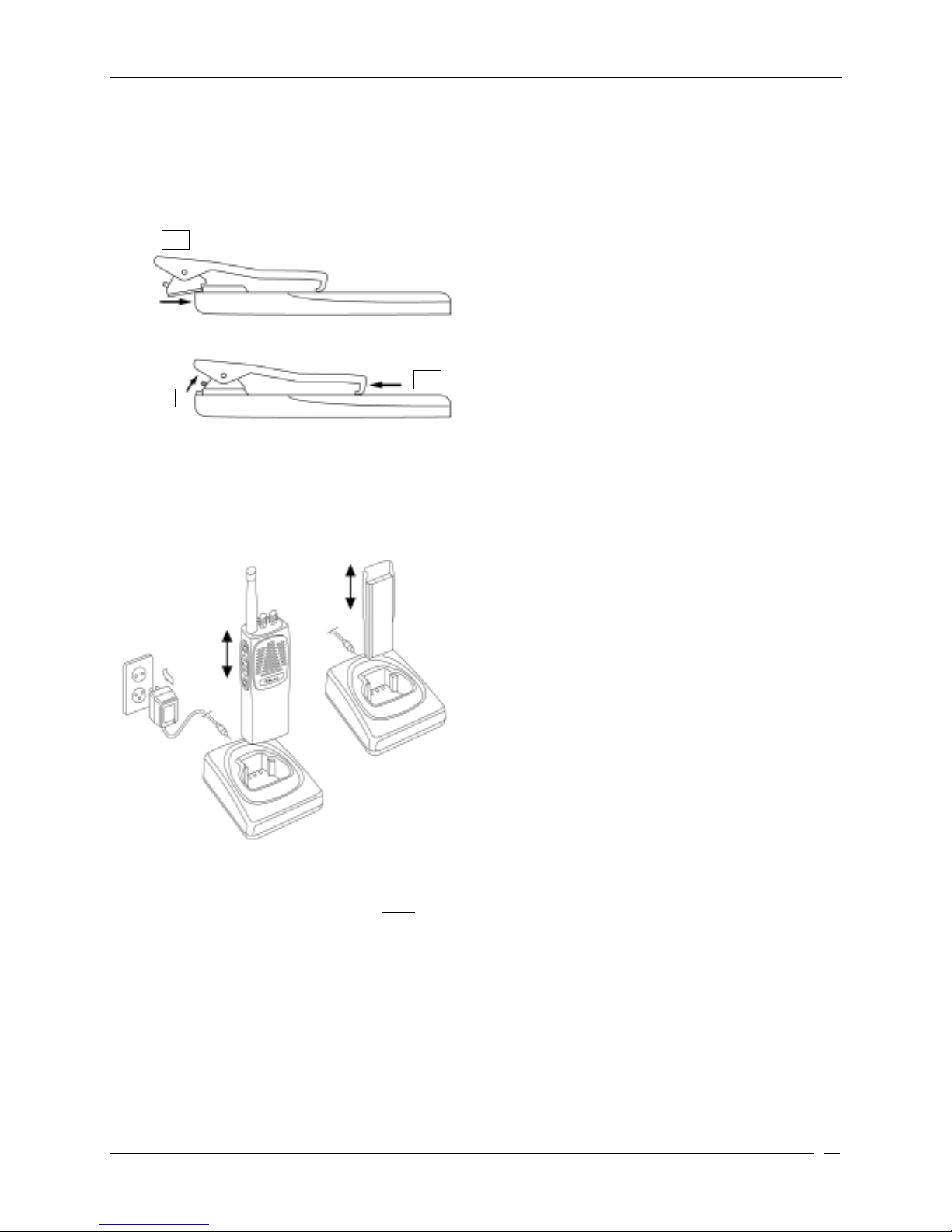
INSTALLING/REMOVING THE BELT CLIP ................................................................................................................. 10
CHARGING THE BATTERY PACK............................................................................................................................. 10
BASIC OPERATIONS ......................................................................................................................................... 11
SWITCHING THE RADIO ON/OFF..........................................................................................................................11
ADJUSTING VOLUME............................................................................................................................................. 11
CHANNEL SELECTION ........................................................................................................................................... 11
RECEPTION .......................................................................................................................................................... 11
MONITOR............................................................................................................................................................. 12
TRANSMISSION .................................................................................................................................................... 12
TRANSMISSION POWER........................................................................................................................................ 12
SCANNING CHANNELS.......................................................................................................................................... 13
ADVANCED OPERATIONS............................................................................................................................... 13
HANDSFREE TRANSMISSION (VOX) ..................................................................................................................... 13
CARE AND MAINTENANCE............................................................................................................................. 15
BATTERY PACKS .................................................................................................................................................. 15
Information on rechargeable batteries.......................................................................................................... 15
Properly charge of battery packs................................................................................................................... 15
Memory effect................................................................................................................................................. 15
Erasing memory effect.................................................................................................................................... 16
Warnings for battery and chargers use ......................................................................................................... 16
RADIO MAINTENANCE.......................................................................................................................................... 17
Cleaning battery packs................................................................................................................................... 17
Cleaning the radio.......................................................................................................................................... 17
Connectors...................................................................................................................................................... 17
OPTIONAL ACCESSORIES............................................................................................................................... 18
Microphone connector................................................................................................................................... 18
QUICKREFERENCE .......................................................................................................................................... 20
OPERATION RESUME............................................................................................................................................. 20
SERVICE:.............................................................................................................................................................. 21
LIMITED WARRANTY....................................................................................................................................... 22
INDEX.................................................................................................................................................................... 23

HP105/HP405 User manual
Page. 3
Introduction
Congratulations. HP105/HP405 is a Professional Radio. Its rugged design allows it to be your reliable
partner even during hard working days.
To extend the flexibility the radio is provided with VOX function, which allows switching the transmission
just by talking in full hands free condition.
Transceiver’s specifications provided in HP105/HP405 are compliant with ETS 300 086, moreover its top
level design and resistance are compliant with IEC529 level IP54 and MIL STD 810 C, D, E.
Alan USA is committed to continuous quality improve, for this reason specifications may vary without prior
notice.
Warning notes
Every effort has been made to ensure that the information in this document is complete, accurate, and up-
to-date. Alan USA assumes no responsibility for the results of errors beyond its control. The manufacturer
of this equipment also cannot guarantee that changes in the equipment made by non authorized people will
not affect the applicability of the information in it.
Safety
Your HP105/HP405 handheld transceiver has been carefully designed to give you years of safe, reliable
performance. As with all electrical equipment, however, there are a few basic precautions you should take
to avoid hurting yourself or damaging the radio:
Read the instructions in this handbook carefully. Be sure to save it for future reference.
Read and follow all warning and instruction labels on the radio itself.
Don’t carry the transceiver by the antenna. This may damage the antenna or antenna terminal. Grasp
it by its base (not the tip!) when you need to place or remove it.
Don’t keep the radio with the antenna very close to, or touching exposed parts of the body, while
transmitting. The radio will perform best if the microphone is 5-10 cm away from the mouth and the radio
is vertical.
Be sure the PTT key is not depressed when you don’t need to transmit.
Do not operate the radio near unshielded electrical blasting caps or in an explosive atmosphere.
Don’t transmit without the antenna fitted on the radio. Though it is provided with a protection, it may
damage the TX output final stage.
Respect the environment conditions. The radio is designed to be used in heavy environments,
however avoid exposing it to extremely hot or cold temperature (out of the range between –30 to +60°C).
Don’t expose the transceiver to excessive vibrations as well as dusty or rainy places.
Never try to disassemble or service the radio by yourself (aside from the routine maintenance
described in this handbook). It will immediately void the warranty and you may cause damage requiring
extensive repair work. Always contact your local dealer for assistance.
Grasp your radios firmly. Otherwise it may fall and be damaged.

HP105/HP405 User manual
Page. 4
Use only genuine accessories. Non original ones could seriously damage your handheld transceiver.
Do not use your radio near water, or spill liquid of any kind into it. If the transceivers get wet
immediately dry it by a soft and clean cloth.
Switch the radio off before you clean it. Strictly follow the directions reported in the paragraph “Care
and maintenance”.
Handle the battery properly. Strictly follow the directions reported in “Care and maintenance”.
Be certain that your power source matches the rating listed for the supplied battery charger (AC adapter).
If you are not sure, check with your dealer or with your local power company.
To avoid damaging the power cable of the battery charger, do not put anything on it or place it where it
will be walked on.
This product complies with the requirements of the Council Directives 89/336/EEC and 73/23/EEC on the
approximation of the laws of the member states relating to electromagnetic compatibility and low voltage.
NOTE TO USERS OF 80-400 TRANSCEIVER:
WARNING
Your wireless hand-held portable transceiver contains a low power transmitter.
When the Push-to-Talk (PTT) button is pressed it sends out radio frequency
(RF) signals. The device is authorized to operate at a duty factor not to exceed
50%. In August 1996, the Federal Communications Commission (FCC) adopted
RF exposure guidelines with safety levels for hand-held wireless devices.
To maintain compliance withthe FCC's RF exposure guidelins, this transmitter
and it’s antenna must maintaina a seperastion distance of least 2 inches (5
centimeters) from your face. Speak in a normal voice, with the antenna pointed
up and away from the face at the required separation distance. The beltclip is
for storage purposes only. DO NOT TRANSMIT WHILE USING THE BELT
CLIP. To transmit, hold the device away from your body and ensure the antenna
is at least least 2 inches (5 centimeters) from your body when transmitting.

HP105/HP405 User manual
Page. 5
Conventions and Symbols in this Book
!This symbol marks a ‘note’. Notes are hints or tips which offer additional information to help you.
"This symbol marks a ‘caution’. Cautions are special notices which you should read and follow
carefully to avoid possible damage to your equipment and to avoid potential danger to
yourself or other people.
Key names will be highlighted in bold.
Important sentences and words are highlighted in Italic.

HP105/HP405 User manual
Page. 6
Part Names and their functions
Please have a look to the following parts description in order to familiarize with the transceiver’s main parts
and controls. Numbers in brackets refer to the illustration.
Top
[1] Antenna connector. Fit the antenna to this
connector (MX thread type).
[2] Power ON/OFF knob. Rotate this knob to turn the
transceiver on and off.
[3] Channel selector knob. Rotate this knob to select
the operative channel.
[4] Status LED. Glows in different colors to show the
current radio’s status.
Front
[5] Speaker. The built in speaker located in this point
emits the reception sound.
[6] Microphone. Your voice is detected by the
microphone located in this place
12
43
5
6

HP105/HP405 User manual
Page. 7
Side (left and right)
[7] Microphone connector. For remote
speaker/microphone, headsets for VOX use and
other accessories. It must be protected with the
supplied rubber cap when not in use. For the
related pin connections please see to
“Microphone connection”.
[8] Battery pack. This NiMH battery pack supplies
energy to your radio.
[9] Release button (located on the battery’s body).
Allows to remove the battery pack
[10]MON (monitor) button. Enables the loudspeaker
for audio monitoring of the tuned channel
[11]PTT (Push To Talk) button. When pressed
switches the transceiver from reception to
transmission
[12]FUNC (Function) button. Enables VOX and Scan
Function. See VOX and Scan chapters.
10
11
12
7
8
9

HP105/HP405 User manual
Page. 8
Setup
Unpacking
The following items are in the package:
(a) Transceiver’s main body
(b) Rubber ducky antenna
(c) Battery pack NiMH 1,300 mA/H
(d) Slow-rate battery charger
(e) Belt clip
(f) User’s guide (this book!)
If something is missing please promptly advise your supplier.

HP105/HP405 User manual
Page. 9
Fitting/removing the antenna
To fit the antenna:
1) Locate the antenna terminal (thread MX connector) on transceiver’s top.
2) Hold the transceiver with one hand and the base (the thicker part) of the antenna with the other one.
3) Attach the included rubber ducky antenna to the antenna terminal by turning it clockwise until it is firmly
locked. Don’t overtighten it.
To remove the antenna do the same described procedure. At step 3 turn the antenna base
counterclockwise.
"Leave the antenna fitted on the radio. You can’t communicate without it. Moreover,
transmitting without the antenna may damage the TX output final stage. For the same reason
use only the supplied antenna.
!The supplied antenna is broadband type and covers the whole spectrum, so it doesn’t need any
alignment procedure. Use only supplied antenna. Unauthorized antennas, modifications or
attachments could damage the transmitter and may violate FCC regulations.
Installing/removing the battery pack
To install the battery pack:
1) Hold the transceiver’s body with one hand and the battery
pack with the other. Put the battery pack onto the bottom of
the transceiver.
2) Gently push the battery pack toward the transceiver’s back
edge.
3) At the end you will hear a click: the battery pack will snap into
place and should be firmly locked.
To remove the battery pack:
1) Press the battery release button located in the back of the
battery pack.
2) Keep the button pressed and gently pull the battery pack
away from the transceiver back edge (the opposite operation
of the previous step 2).
3) Remove the battery pack by separating it from the
transceiver’s body.
1
2
SLIDE DOWN
PUSH DOWN
1
2
PUSH DOWN
LIFT UP

HP105/HP405 User manual
Page. 10
Installing/removing the belt clip
The supplied belt allows you to hang the transceiver up to your belt or jacket when you are not using the
radio and you are just in stand-by condition (ready to receive calls).
To fit the belt clip onto the transceiver’s body:
1) Just gently slide the clip into the appropriate
guides located in the transceiver’s back until it
firmly locks.
To remove the belt clip:
2) Press the belt clip spring;
3) Reverse the order stated in step 1.
Charging the battery pack
To charge the supplied battery pack you have to setup the standard charger and connect the radio as
follows:
1) Connect the jack coming from the AC adapter to
the cradle’s socket.
2) Connect the AC plug of the AC adapter’s power
cable into an earthed AC power outlet.
3) Ensure that the radio is switched off.
4) Insert the radio into the cradle with the keypad
toward you (the three metallic contacts of the
battery pack must touch with the three contacts
inside the cradle).
5) Wait 10-12 hours with the standard charger 2
hours with the rapid charger and remove the
radio.
!Do not remove the radio before the specified
time, otherwise the battery’s duty could be
temporarily reduced.
"Don’t forget to remove the radio slow charger after 10 to 12 hours.
"The battery charger is for indoor use only.
"For the next charges, best duty and battery life please see the chapter “Battery Packs”.
1
23
SLIDE DOWN
LIFT UP PUSH

HP105/HP405 User manual
Page. 11
Basic Operations
This section describes how the standard operations work. Standard operation can be changed by
programming; moreover the functions the radio includes can be modified via an IBM compatible PC. For
this reason the way your radio operates may be upgraded and may slightly differ from what is described
here.
!IMPORTANT: Due to the full programmability of the radio, certain commands could be
unavailable. If in doubt please contact your dealer/radio network administrator for further details.
Switching the radio ON/OFF
To switch the radio on:
1) Rotate the PWR/VOL knob clockwise until the radio is switched on: the CPU will start an autotest
showing in sequence:
•LED will light GREEN, then RED and finally OFF.
•A beep confirms that the autotest is passed
!The self-test goes very fast, therefore the LED could not be seen.
To switch the radio off just rotate the PWR/VOL knob counterclockwise.
Adjusting volume
The PWR/VOL knob is used to adjust the RX volume: just turn it clockwise to increase or counterclockwise
to reduce it.
Channelselection
If your radio has been programmed with more than one channel you can easily change it. To select a
channel, turn the channel selector knob clockwise or counterclockwise until the channel indicator on the
knob matches the wished channel.
Reception
Your radio could be previously programmed to work, channel by channel, in “Open traffic” or “GROUP
MODE (CTCSS/DCS)”. Please have a look to each description and ask your radio network manager or
dealer which mode your radio channels work.
•OPEN TRAFFIC: in this case you will hear any communication which will be transmitted on the
selected channel. When the right carrier is received your squelch will unmute, you will see the status
LED glowing green and you will hear the message.
•GROUP MODE:
•CTCSS/DCS (Continuous Tone Code Squelch System - Digital Coded Squelch): they are systems
which use particular TX signaling (a continuous sub audio tone for CTCSS or a digital code for
DCS) as an access “key” to work a repeater (encoder) or to unlock the party’s signaling sensitive
squelch. This last condition allows sharing more radio networks in the same frequency. In this case
you will receive only messages coming from parties sending a proper TX signaling. During
CTCSS/DCS operation the radio may be set-up so that the appropriate CTCSS/DCS decoder
enables the speaker. Speaker will remain muted until the correct CTCSS tone or the correct DCS

HP105/HP405 User manual
Page. 12
code is received. In case of unmuted speaker, the message will be heard and the status LED will
glow amber. Units of the same group are not affected by communication on the same channel with
wrong CTCSS/DCS.
"CTCSS/DCS allows more than one radio network to share the same frequency. However they
are only useful to avoid disturbing stations not of the same network with messages not related
to them. If more than one station is transmitting at the same time, this will cause interference.
Do not transmit if the status LED is glowing. Wait till until the channel is clear before
transmitting.
"Monitor
Monitor button can enable / disable “GROUP MODE (CTCSS/DCS)”.
1) To enable GROUP MODE. Press MON button. A Sub Audible Tone mutes your speaker.
2) To Disable GROUP MODE. Press MON button. You are working in “Open Traffic”.
!NOTE: if CTCSS/DCS tone is not programmed, GROUP MODE functionis not available.
3) Press and Hold MON button: internal squelch is disabled and your speaker in unmuted. Every
environmental noise is heard.
Transmission
When you need to transmit please get used to follow all these steps:
1) Ensure that the channel is not busy (otherwise you will create interference, please wait for the channel
to clear).
2) Press the
PTT key: the status LED will glow red
3) Start talking at a normal voice level at least 5 cm from the microphone (keep the PTT key pressed).
4) When your message is over, release the PTT
!Don’t shout! It won’t increase the distance range, but rather will make you sound distorted.
!Don’t release the PTT before your message is over or start talking before pressing it, otherwise
your message will be “chopped”.
!A handheld radio doesn’t normally allow you to talk and receive simultaneously, for this reason
make your messages short. When you are talking the other parties can’t, so don’t occupy the
channel too much. Use common sense.
!The radio might be programmed with a timeout timer which will automatically put your radio in
reception (after a preset time) if you talk too much. In this case release the PTT and wait for few
seconds: the radio TX features will be automatically restored. Ask the network administrator
responsible or your dealer for further details.
!The radio might be programmed with a busy channel lock out, which automatically disables
transmission if your channel is busy.
Transmission Power
Your HP105/HP405 can transmit with two power levels according to the distance of your party station(s).
This option is programmed via PC and the user can not modify it. We do recommend, when possible, to
use the Low power: it will increase the battery duty and will reduce the risk to make interference with
stations not belonging to your radio network which may share the same channel with you.

HP105/HP405 User manual
Page. 13
!If the low battery mark is "blinking" (Low Battery indication), the Unit will then automatically revert
to Low RF Power when transmitting in order to help prolong the Battery's operational life. In this
case, two short beeps will be heard before transmission.
Scanning channels
If you have more than one channel programmed, your HP105/HP405 can scan them: in other words it can
cycle through them and stop when a signal is detected.
The advanced scan functions of the radio allow to optionally look for carrier or carrier with CTCSS/DCS or
CTCSS.
1) To activate the scan Switch Off and thenSwitch ON the radio holding MON and FUNC buttons.
2) A long beep will be heard when enter the SCAN MODE.
3) During scanning the LED will blink amber.
4) Only the channel in the Scan List will be monitored for activity. The Scan List is programmed via PC.
5) During scanning the channel selector knob becomes invalid.
6) To stop channel scan Switch Off and then Switch ON the radio holding MON and FUNC buttons.
7) One among the programmed channels can be assigned as Priority Channel. The scanning will look
back at the priority channel with high frequency.
8) User can select the priority channel:
9) To select Priority channel, before starting the Scan Mode (before switching On the radio) select the
channel using the selector knob.
!NOTE: If the Scan List has no channels, a low tone (error beep) will be heard when you switch
On the radio holding MON +FUNC and radio will not start the Scan Mode. At least two channels
must be in the Scan List for the Unit to be put in the SCAN Mode.
!When a proper signal is received on a channel, the radio will stop scanning and audio will
become audible. When the activity on that channel ceases, the unit will automatically resume
scanning.
!If CTCSS/DCS have been previously programmed, the scanning will stop only if the received
carrier has the appropriate signaling.
!If PTT is pressed during scanning, the radio will transmit on the last received channel if traffic is
within the last 15 seconds. Otherwise the radio will transmit on the priority channel. In case of no
activity, the Unit will automatically resume scanning.
Advanced Operations
In this section we’ll describe some advanced operation which you can do with your handheld transceiver:
Handsfree transmission (VOX)
VOX (Voice Operated eXchange) is an automatic system that allows you to automatically switch the
transmission in hands free mode just by speaking in the built-in microphone of a headset (not provided with
the unit). Please ensure that the handset is suitable for your transceiver as reported in the paragraph
“Microphone connection”. To insert the VOX and adjust sensitivity:

HP105/HP405 User manual
Page. 14
1) Switch on the radio keeping pressed the FUNC key.
2) Connect the optional headset with built-in microphone to the microphone connector located on the
transceiver’s side.
10) Ensure that the headset’s built-in microphone is located close to the side of your mouth.
11) Hold the FUNC key for more than 2 seconds to toggle VOX sensitivity from HIGH to LOW and vice
versa. Adjust the VOX sensitivity in order to ensure a stable transmission when speaking with a normal
voice level.
"We recommend to set the sensitivity as low as possible. A too high value could cause
accidental transmissions, especially in high noise environments.
!PTT button is disabled during VOX.

HP105/HP405 User manual
Page. 15
Care and Maintenance
Battery Packs
Information on rechargeable batteries
•When the battery pack is new it doesn’t provide 100% of its efficiency; it means that it might be
discharged earlier. To reach the full battery life you have to “run-in” the battery with at least 3-4
deep charging/discharging cycles, after that it will reach its maximum capacity. Please see
“Properly charge of battery packs” for further details.
•Should you properly use the battery pack, you will obtain at least 400 charging/discharging cycles
with slow charger or 300 with the rapid charger. The battery duty will progressively reduce after
2/3 of its life (approx.).
•Rechargeable battery packs lose their charge with the time if left unused (self-discharge); this is
normal. A NiMH (Nickel Metal Hydride) battery can reduce 10 to 20% of its stored energy in few
days.
Properly charge of battery packs
1) Ensure that the radio is switched off.
2) Insert the radio into the cradle as explained in the paragraph “Charging the battery pack”
3) Wait the necessary time to provide a full charge. If the pack isn’t completely discharged you will need
less than 10-12 hours (using slow charger).
"Don’t overcharge the battery: always remember to remove the radio after the necessary time.
"The battery charger is for indoor use only.
!When possible, charge the battery when it is fully discharged or, at least, you have used it for the
major part of its duty. Otherwise the battery’s duty could be temporarily reduced. Please see the
paragraph “Memory effect”.
!Don’t remove the radio before the necessary time, otherwise the battery’s duty could be
temporarily reduced. Please see the paragraph “Memory effect”.
Memory effect
The supplied NiMH (Nickel Metal Hydrate) battery pack is made with a more advanced technology than
normal NiCd (Nickel Cadmium) battery. For this reason it is virtually free of what is called “memory effect”,
which affects NiCd batteries. Memory effect is a temporary capacity reduction which reduces the battery
duty. Memory effect may occur just if you regularly charge the battery when you haven’t discharged it at
least at 50-70%. Memory effect can be easily avoided by following these simple rules:

HP105/HP405 User manual
Page. 16
•When possible charge battery packs only when they are completely discharged, i.e. when the
battery icon has no bars inside.
•Don’t remove the battery from the charger before the necessary time to provide a full charge.
•Provide at least two deep charge/discharge cycles per month.
•The best way to avoid memory effect is to use two battery packs and alternate their use with the
radio. This will allow you to keep on your transceiver’s operation by replacing the battery pack just
when it’s fully discharged and use the spare (charged) one. At the end of your working day you will
charge the discharged pack for 10-12 hours.
Erasing memory effect
Just applying 3-4 deeper charge/discharge cycles can easily erase memory effect:
1) Use the battery fitted in the radio and wait till the radio switches off.
2) Wait at least one hour and then try to switch on the radio: you will note that some energy has restored
in the battery, because the radio can be switched on.
3) Leave the radio in RX until the radio switches off again.
4) Repeat steps 2) and 3) three times.
5) Fully charge the battery for 10-12 hours and check the battery duty. If some memory effect still exist
go back to step 1.
!If the battery duty doesn’t improve after three of the over stated cycles, it means that your battery
pack is faulty or has reached the end of life (please see “Information on rechargeable batteries”).
In this case please ask your dealer to provide a new battery pack.
Warnings for battery and chargers use
Please use these cautions to avoid damaging battery packs or the transceiver:
"Before using the battery charger carefully read any related warning or caution.
"Don’t short battery terminals: this may cause fire, burns or explosions.
"Never dispose batteries into fire as they may explode. Strictly follow any disposal regulation
of your country.
"Use only authorized batteries and chargers. The use of non-authorized accessories may cause
burns, fire or explosions as well as causing serious damage to the radio/battery or serious
injuries to people.
"Battery chargers are for indoor use only.
"Be certain that your power source matches the rating listed for the supplied battery charger
(AC Adapter). If you are not sure, check with your dealer or with your local power company.
"To avoid damaging the power cable of the battery charger, do not put anything on it or place it
where it will be walked on. Insert the plug in socket provided with earth connection.
"Avoid strong shocks. Don’t use the charger if it received a strong shock, has fallen down or it
appears damaged; immediately contact an authorized service station.

HP105/HP405 User manual
Page. 17
"Never try to disassemble or service the charger by yourself. Always contact your local dealer
for assistance.
"To reduce the risk of electric shocks disconnect the plug before providing any cleaning or
maintenance. Grasp the plug (not the cable) to remove the plug from the socket. The use of
non-suitable extension can cause fire or electric shocks.
"Battery performance will be degraded when exposed to temperatures below -20°C (-4°F) or
greater than 35°C (95°F) during their use. Also do not charge them outside the range of +5°C
(41°F) to +55°C (149°F).
Radio maintenance
Cleaning battery packs
Wipe the battery contacts with a clean and lint free cloth to remove dirt, grease or any other material which
may prevent a good electrical contact. If contacts are very dirty you can also wipe them using a soft pencil
rubber (not hard erasers for ink!). If you feel that battery contacts aren’t still working properly, please
contact your authorized dealer.
"Do not use liquid, alcohol or aerosol cleaners.
Cleaning the radio
Wipe the radio with a clean and lint free cloth to remove dust. If it is very dirty, you can use a damp
(slightly moistened with water) cloth.
"Do not use liquid, alcohol or aerosol cleaners.
!If you normally use your radio in dusty or hard environments, we do recommend using the
optional carrying case. Please see “Optional accessories”.
Connectors
When the connectors are not being used, they should be fitted with the supplied cover caps.
"Only suitable accessories must be connected to the related connectors.

HP105/HP405 User manual
Page. 18
Optionalaccessories
These optional accessories can be used to improve the transceiver’s performances:
Spare battery pack. It extends the duty time and minimizes the possibility of memory effect (please see
“Memory effect”).
Slow charger. It recharges the battery packs in 10 to 12 hours
Rapid charger. It recharges the battery packs in 2 hours and provides trickle charge when they have
reached their full charge.
Carrying case. It protects your radio against small shocks and scratches; the best for use in hard
environments.
WARNING
Your wireless hand-held portable transceiver contains a low power transmitter. When the Push-to-Talk
(PTT) button is pressed sends out radio frequency (RF) signals. The device is authorized to operate at a
duty cycle factor not to exceed 50%. In august 1996, the Federal Communications Commissions (FCC)
adopted RF exposure guidelines with safety levels for hand-held wireless devices. The FCC has issued the
following warning,
To maintain compliance with the FCC’s RF exposure guidelines, this transmitter and its antenna must
maintain a separation distance of at least 2 inches (5 centimeters) from your face. Speak in a normal
voice, with the antenna pointed up and away from the at the required separation distance. The belt clip is
for storage only. DO NOT TRANSMIT WHILE USING THE BELT CLIP. To transmit, hold the device away
from your body and ensure the antenna is at least 2 inches (5 centimeters) from your body when
transmitting.
Microphone connector
The microphone connector is designed for the connection of two basic accessories (not supplied as
standard): The microphone is not intended for use with the belt-clip for transmission in body-worn
operating configuration.
An external speaker/microphone
A headset with built-in microphone, which additionally adds the VOX facility. In other words you can
switch the transmission just by talking at the headset’s microphone in hands free convenience. For
further details please see “Hands free transmission (VOX)”.
Any kind of accessory for the above stated purposes can be connected to the microphone connector,
provided that they meet the following requirements:
Jack connectors for Speaker (SPK) and Microphone (MIC) must be respectively standard type 3,5 mm
SPK
Spk GND
MIC
MicGND

HP105/HP405 User manual
Page. 19
and 2,5 mm. and connected as follows:
The suggested speaker input impedance is 8 Ohms
The microphone should be condenser low-impedance type.
Any accessory should be of high quality suitable for professional use.
"Please don’t connect any accessory that you are not sure of meeting the above stated
requirements. You could create serious damage to your radio. If in doubt please contact your
authorized dealer.

HP105/HP405 User manual
Page. 20
Quick reference
Operation resume
Once you are familiar with your transceiver you will know that it’s very easy to use any one of its functions,
you just have to do what follows:
1) Press the
MON to enable/disable GROUP MODE (CTCSS or DCS).
2) Press and Hold MON button to enable/disable the squelch.
3) Press the
MON + FUNC keys at the switching ON to enter the SCAN.
4) Before entering the SCANMODE, use the channel selector knob to select the priority channel.
5) Hold the
FUNC key and switch on the radio to enable/disable VOX.
6) When VOX function is enabled, press the FUNC to set HIGH or LOW VOX sensitivity.
"Press the MON key and switch on the unit. The unit enters the PROGRAMMING MODE. This
operation is only allowed to an authorized person.
This manual suits for next models
3
Table of contents