alatech CB100 User manual

1
Before Use
We thank you for purchasing the Cycling Computer.
In order to correctly and effectively use the functions of this device,
please read this manual carefully and keep it in a safe place for
future reference.
Package Contents
• Cycling Computer
• Bike Mount
• Handlebar Clamp Connector Base
• Speed Sensor
(including Magnet, Rubber pad)
• Cadence Sensor
(including Magnet, Rubber pad)
• Heart Rate Transmitter
(include Elastic belt)
• Cable Ties
• Screws
• User Manual
• Instructions manual for
Battery Replacement
• Warranty
Thank you for purchasing this product.
Disclaimer
• The CB100 is for use on bicycles only. It is not designed for medical use.
• To ensure correct display values, make the adjustments and enter your
personal data when you use this device for the first time and also after
changing batteries or resetting. Please refer to the chapter on user
configuration.
• The values measured and displayed should be treated as reasonably
accurate.
• Alatech is not responsible for any claims of loss or damage from third
parties incurred from the use of this device.
• Alatech reserves the right to change the specifications of the hardware
and software described in this manual at any time without prior notice.
Magnet for Cadence Sensor
Magnet for Speed Sensor
Handlebar Clamp
Connector Base Bike Mount
Cadence Sensor
Cycling Computer (Wireless)
Speed Sensor

2
繁中
1 Getting started with Cycling Computer 5
1-1 Before use 5
1-2 Steps to wear the transmitter 5
1-3 Know and customize your maximum training output 6
1-4 Keys 9
1-6 Basic operation 11
2 Using the Cycling Computer for the first time 12
2-1 Installing the Cycling Computer 12
2-2-1 Installing the Speed Sensor (SPEED) 14
2-2-2 Installing the Cadence Sensor (CADENCE) 15
2-3 BASIC SETTINGS 17
2-3-1 Accessing the Setting Mode 17
2-3-2 User Setting (USER SET) 17
2-3-3 Heart Rate Setting (HR SET) 18
2-3-4 Timer Setting (WATCH) 20
2-3-5 Bike Setting (BIKE SET) 21
2-3-6 General Settings (GENERAL) 24
3 BIKE MODE 25
3-1 Accessing Bike Mode 25
3-2 BIKE MODE Menu 26
3-3 How to Switch the Menu 29
3-4 Things You Should Know 30
4 TRAINING MODE 30
4-1 Accessing the TRAINING MODE 30
4-2 TRAINING MODE EXPLAINED 31
4-3 How to Switch the Menu 32
4-4 Things You Should Know 33
Content

5 TIMER MODE 34
5-1 TIMER MODE 34
5-1-1 Accessing the TIMER MODE 34
5-1-2 Icon Flow Explained 34
5-2 Countdown 34
5-2-1 Accessing the Countdown 34
5-2-2 Icon flow explained 35
6 Files 35
6-1 Accessing Files 35
6-2 Check Files 36
6-2-1 Check Files 36
6-2-2 Check LAP Data (LAP Data) 38
6-3 FILES Operation Flow 40
6-4 File Management 40
7 Specifications 40
9 Q & A 43
10. Chinese to English Glossary 45

4
繁中
1Getting started with Cycling Computer
1-1Before use
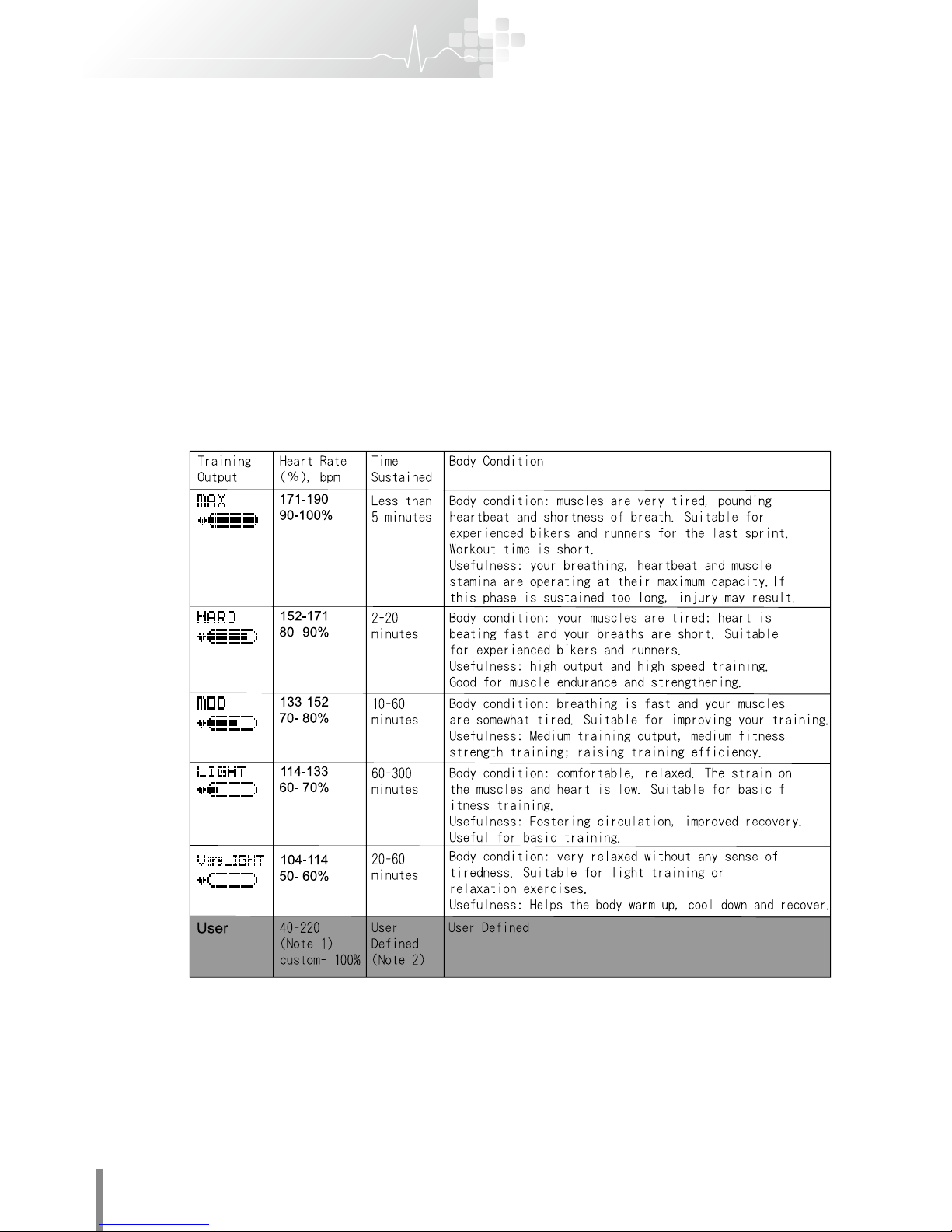
1. When installed on a bicycle this device can display the speed,
number of laps and cadence rate. It can also help you to monitor
your training output during a fitness session based on your
gender, age, body weight, height and maximum heart rate. It will
also measure the time used and calories burned. This device
helps you to progressively realize your dreams of better physical
performance and an improved physique.
2. The device has speed, lap and heart rate sensors built in that
provide readouts of cycling speed, cadence, and real time heart
rate.
3. When using the device for the first time and after battery changes
or resetting, please adjust the different sensors and enter your
personal information to ensure data accuracy. Please refer to User
Setting 2-3, Page 14 for details.
1-2 Steps to wear the transmitter
The Heart Rate Transmitter Belt reads your real-time heart
rate and transmits this to the cycling computer. Please refer to
the following steps to wear the Transmitter before you start to
exercise.
1. Fix the hook on one side of the band to the end of the chest strap.
2. Adjust the length of the band so the chest strap fits comfortably on
your body and won’t slip or loosen during training.
3. Wet the conducting pads on both sides of the chest strap fully.
4. Adjust the strap so that the Logo faces away from your chest.
Move the strap up to just under your pectorals and then hook the
other end up with the band.
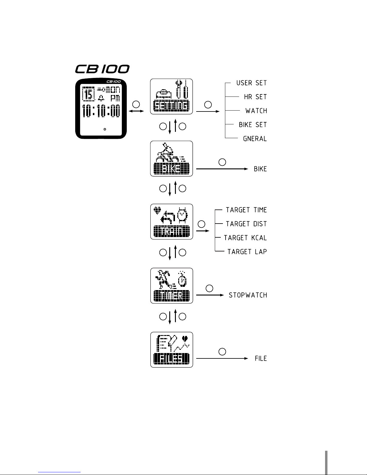
5. Change the chronograph to BIKE MODE and check if the heartbeat
symbol is displayed as a regular rhythm. If the signal is steady
the chronograph will detect your heartbeat and display it on the
monitor within 15 seconds.
2.1. 3. 4. 5.
Conducting pads for
the Transmitter

5
1-3 Know and customize your maximum training output
The chart below shows the heart rate level using %HR max. HR
max = 220 - Age with every 10 years of age as an age zone. This
chart is a reference for appropriate training output using the heart
training mode.
• The unit for heart rate is bpm (beats per minute), or heartbeats per
minute.
• Maximum heart rate = 220 -age. If your age is 20, then 220-20 =
200 bpm, and your maximum heart rate is 200 bpm.
• Maximum heart rate (maximum heart rate, MHR, or HRmax) refers
to the maximum heart rate for optimizing exercise or stamina. It is
often used as the prescribed index for training output in order to
find the THR. The most direct and accurate method of measuring
the maximum heart rate is to have this done by a doctor or
professional. An Exercise Stress Test is conducted and monitoring
is done by an electrocardiograph (ECG). Or you can use the
simple age formula to calculate your personal maximum heart rate.

6
繁中
• Target heart rate
=training output (%) × maximum heart rate (HRmax).
• The target heart rate (THR) or training heart rate is used to find
the ideal rate for the optimal performance of aerobics to maximize
the benefit to your heart and lungs. You can find your own upper
and lower range target heart rate using the maximum heart rate
formula (%HRmax).
• In general, for persons with less than optimal health, it is
recommended that the low-strength target heart rate range be set
at 60% or below.
This table has six training programS of exercise intensity heart rate zone:
• Note 1: The 40-220 range is the normal CB100 setting range, but
the range values can be user defined. The graph will show the
strength of the training according to the value configured.
• Note 2: If the user defined training output is above the 90-100%
range, it is recommended that the Time Sustained should be less
than 5 to avoid sports injury.

7
1-4 Keys
The has 5 keys, see the figure below:

8
繁中
1-5 Main screen
The Main Menu is divided into 2 sections: The top section
displays general information,The lower section displays the heart
and cadence rates.
1. Press the A Key to turn on the backlight. The time the light stays
on can be user defined as Always, Flash (BIKE MODE only) or 3S.
It can be difficult to see the backlight under the sun.
2. On the Time Main Menu, press and hold the A Key for 3 seconds
to lock the keys. The bottom left corner of the Menu will display a
“ ” symbol. Repeat the above to unlock the keys.
3. Low battery indicator “ ”. Please replace low batteries as
soon as possible to maintain the CB100 in working condition.
4. In general mode, keys C, D, and E have a shortcut key function
(see 1-5 Basic operation and the CB100 main function structural
diagram, page 10).
Week
AM/PM
Time
Cadence number
Maximum/average
cadence number
Maximum/average
heart rate
Alarm
Bike1/Bike2
Calendar
Heart rate value
Heart rate
display
Key lock
Pedal sensor
connection signal

9
1-6 Switching Mode
Main function structure illustration
From the general Menu,
press the E shortcut key to enter the BIKE MODE directly
(by passing the Welcome Menu for BIKE MODE).
Press the D shortcut key to enter the TRAINING MODE directly
(by passing the Welcome Menu for TRAINING MODE).
Press the C shortcut key to enter the FILE MODE directly
(by passing the Welcome Menu for FILE MODE).
E
E
E
E
E
CD
CD
CD
CD
B

10
繁中
2 Using the Cycling Computer for the first time
2-1Installing the Cycling Computer :
Either on the Handlebar or on the Handlebar Stem
1. First , screw the Bike Mount and handlebar clamp connector base together
tightly.
2. And then use the ties to secure the device to the Handlebar or Handlebar
Stem . Make sure the handlebar moves freely before securing .
3. Slide the Cycling Computer into the socket of the Bike Mount until you
hear a click sound , make sure the Cycling Computer is in the right
position and will not fall off.
4. To remove the Cycling Computer : press the lever of the Bike Mount ,
push the Cycling Computer out of the Bike Mount from the other side.
2-2 Installing the Sensors
2-2-1 Installing the Speed Sensor (SPEED) : Install the Speed Sensor on
the same side of the Cycling Computer . The Speed Sensor should form a
90angle with the Cycling Computer within a maximum distance of 50cm /
1.6404ft.
1. Use the ties to fasten the Speed Sensor along with the Rubber Pad on the
front fork of the bike, ALATECH logo faces outward.
2. Then secure the magnet to a spoke of the front wheel, the magnet should
face the Speed Sensor. Adjust the magnet position to be as high as the
Speed Sensor and in maximum distance of 5mm / 0.19685ft. between
each other.
3. Finally, turn the front wheel, enter to the screen of BIKE SET_Speed
Coding of the Cycling Computer, and see if the signal showed at 3~4
2.
3.
Bike Mount
CB100
1.
2.
5mm
Magnet
Speed
1-1.
Rubber
pad
Speed
1-2.
5mm

11
grids. (See P.? for the Steps of the signal interpretation. )
If there is no sense of the signal or less grid showed, then adjust
the relative position of the magnet and Speed Sensor.
2-2-2 Installing the Cadence Sensor (CADENCE) : Install the
Cadence Sensor at the same side of the Cycling Computer , the
maximum distance from the bevel angle of both is 80cm / 2.6247ft..
1. Use the ties to fasten the Cadence Sensor along with the Rubber Pad
on the down tube of the bike, ALATECH logo faces outward. ( For Small
Wheel Bike or Folding Bike, fasten the device on the seat tube. )
2. Then secure a magnet on the inside of the crank, ALATECH logo faces to
the Cadence Sensor. Adjust the magnet position in a distance of 5mm /
0.19685ft from the Cadence Sensor, make sure there is no collision while
pedaling.
3. Finally, turn the pedal, enter to the screen of BIKE SET _Cadence Coding
of the Cycling Computer, and see if the signal showed at 3~4 grids. (See P.
? for the Steps of the signal interpretation. )
4. If there is no sense of the signal or less grid showed, then adjust the
relative position of the magnet and Cadence Sensor.
Note :
• Cut off the extra length of the ties to avoid any danger while riding.
• The receiving distance could be increased or decreased due to the
installation position, the position of the Sensors or Cycling Computer can
be adjusted slightly.
• Before riding, you are requested to enter the tire size of the bike
i
n the
setting mode. For details about configuration, refer to 2-3-5 Bike
Setting.
2.
5mm
1-2.
磁鐵
Cadence
1-1.
1
.
.
.
橡膠座
Cadence
4.

12
繁中
2-3 INPUT BASIC SETTING (SETTING)
2-3-1 Accessing the Setting Mode
On the General Menu, press the B Key Mode. Enter the User Setting page
(SETTING), and press E OK to confirm.
• Check if the Menu is locked “ “;
to unlock, press and hold A for 3 seconds.
2-3-2 User Setting (USER SET)
• After completing a setting, press the B Key to quit the User Setting mode
(User Set).

13
2-3-3 Heart Rate Setting (HR SET)
On the User Menu select HR SET and press the E Key to enter.
• After completing a setting, press the B key Mode to leave the User
Setting mode (User Set).
• Note 1: The default maximum heart rate (HR MAX) is based on
your age, height and weight. The maximum heart rate value is for
reference only. You can enter your custom maximum heart rate
value to suit your own training regimen.
• Note 2: Physical Activity Status Scale, PAR.

14
繁中
Physical Activity Status Scale, PAR

15
Percentile Value for Maximal Aerobic Power chart
The oxygen uptake index will increase as your stamina increases
and decrease as you get older. Generally, world-class athletes
have a higher aerobic uptake index. Studies show that when the
aerobic uptake index falls below the 20th percentile, it reflects a
sedentary lifestyle without much exercise that may increase the
amount of free radicals inside the body, which is harmful to your
health. Please compare your aerobic uptake measured by the
chronograph with the chart below and learn about your ability for
maximal oxygen uptake.
(Units: ml/kg/min)
Percentile Value for Maximal Oxygen Uptake in Men (unit: ml/kg/min)
Percentile
90
80
70
60
50
40
30
20
10
Age
20~29
55.1
52.1
49.0
47.4
44.2
42.6
41.0
37.8
34.6
30~39
52.1
50.6
47.4
44.2
42.6
41.0
39.4
36.2
33.0
40~49
50.6
49.0
45.8
44.2
41.0
39.4
36.2
34.6
31.4
50~59
49.0
44.2
41.0
39.4
37.8
36.2
34.6
31.4
29.9
Over 60
44.2
41.0
37.8
36.2
34.6
33.0
31.4
28.3
26.7
Percentile Value for Maximal Oxygen Uptake in Women (unit: ml/kg/min)
Percentile
90
80
70
60
50
40
30
20
10
Data were obtained from the initial examination of apparently health men and women
enrolled in the Aerobics Center Longitudinal Study(ACLS), 1970 to 2002.
Age
20~29
49.0
44.2
41.0
39.4
37.8
36.2
33.0
31.4
28.3
30~39
45.8
41.0
39.4
36.2
34.6
33.0
31.4
29.9
26.7
40~49
42.6
39.4
36.2
34.6
33.0
31.4
29.9
28.3
25.1
50~59
37.8
34.6
33.0
31.4
29.9
28.3
26.7
25.1
21.9
Over 60
34.6
33.0
31.4
28.3
26.7
25.1
23.5
21.9
20.3
Maximal Aerobic Power can improve with training and decrease with age, world class
athletes typically have high VO2max. Research suggests that the VO2max below the 20th
percentile for age and sex, which is often indicative of a sedentary lifestyle, is associated
with an increased risk of death from all causes.
You can compare your own VO2max value measured by this watch with the reference list
on page 20 for better understanding of your health status.

16
繁中
2-3-4 Timer Setting (WATCH)
• Note 1: The icon for alarm on the General Menu is “ "After
completing each setting, press the B key to leave the User Setting mode .
2-3-5 Bike Setting (BIKE SET)

17
• This chart can memorize two sets of bike values and the setting methods
for both are the same.
• To select between BIKE1 and BIKE2, highlight a bike and press the B
key Mode to go back to Watch Mode and confirm whether icon or is the
desired bike. If the sensor coding time runs over 4 minutes, the screen will
display coding fail.
• Note 1: Installing on standard bikes (road bike/mountain bike/folding bike)
(see 2-2) with regular methods should display a signal strength in the
middle range. For signals over the standard or not reaching the standard,
the installation location must be adjusted to enable optimal signal display
(refer to the chapter on installing the sensor).
• Note 2: If only one bar shows when the Cadence sensor is coding, it
means that the signal is weak and cannot be used normally. If all the bars
show (“ "), it means the signal is too strong and could interfere with
the signal from the chest strap. It is advisable to adjust the angle and
distance until the display shows 3 or 4 bars.
You have the following alternatives for finding out the wheel size of
your bike:
• Method 1:
Chart 1. (Bike Wheel Adjustment Chart)
Tire size L (mm) Tire size L (mm) L (mm) Tire size L (mm)
12 x 1.75 935 26 x 1(59) 1913 650 x 20C 1938
14 x 1.50 1020 26 x 1(65) 1952 650 x 23C 1944
14 x 1.75 1055 26 x 1.25 1953 650 x 35A 2090
16 x 1.50 1185 26 x 1-1/8 1970 650 x 38A 2125
16 x 1.75 1195 26 x 1-3/8 2068 650 x 38B 2105
18 x 1.50 1340 26 x 1-1/2 2100 700 x 18C 2070
18 x 1.75 1350 26 x 1.40 2005 700 x 19C 2080
20 x 1.75 1515 26 x 1.50 2010 700 x 20C 2086
20 x 1-3/8 1615 26 x 1.75 2023 700 x 23C 2096
22 x 1-3/8 1770 26 x 1.95 2050 700 x 25C 2105
22 x 1-1/2 1785 26 x 2.00 2055 700 x 28C 2136
24 x 1 1753 26 x 2.10 2068 700 x 30C 2146
24 x 3/4 Tubular 1785 26 x 2.125 2070 700 x 32C 2155
24 x 1-1/8 1795 26 x 2.35 2083 700C Tubular 2130
24 x 1-1/4 1905 26 x 3.00 2170 700 x 35C 2168
24 x 1.75 1890 27 x 1 2145 700 x 38C 2180
24 x 2.00 1925 27 x 1-1/8 2155 700 x 40C 2200
24 x 2.125 1965 27 x 1-1/4 2161 29 x 2.1 2288
26 x 7/8 1920 27 x 1-3/8 2169 29 x 2.3 2326
(The wheel size shown on the chart represents the normal sizes according to the wheel type. For pr
ecise sports data,
manual measuring is recommended.)

18
繁中
Method 2
How to measure the diameter of the front wheel
To get the necessary wheel data, follow the steps below:
1. Set the bike upright and use a tape measure
to determine the diameter of the wheel.
2. Multiply the diameter by 3.14 to get the
circumference.
3. Enter the value into the Chronograph.
4. Press B or E to exit or enter the
next setting screen.
2-3-6 General Settings (GENERAL)
• Note 1: Night Mode: Always on (ALWAYS), Flash (FLASH) and on
for 3 seconds (3S).
• Always on (ALWAYS): Press the A key to set the backlight to
“always on", press and hold the A key to keep it on and press
again to turn off the backlight. This can be used in every mode.
Using the ALWAYS mode for a long time will reduce the life of the
battery.
• Flash Mode (FLASH): Press the A key and backlight flash will be
available in BIKE MODE.
• 3-second mode (3S): Press the A key and the backlight will be on
for 3 seconds. Can be used in any mode.
• Note 2: Total Trip distance (ODO.DST): Records the total distance
rode. After a session, the distance will be updated but the total trip
distance data cannot be cleared.

19
• Note 3: Total Riding Time (Total TIME): Records the total
time of your session. After the session ends, the Total
Riding Time will be automatically updated, but the Total
Riding Time data cannot be cleared.
• The combination keys for resetting the Chronograph are (B
+ C + D + E). The Chronograph will reset after a beep. After
resetting, the Chronograph screen will turn off. Press any
key to turn on the Chronograph. After turning on, press any
key to shut off the beep and start using Chronograph.

20
繁中
3 BIKE MODE
3-1 Accessing Bike Mode
A.
Standard method: In Watch Mode, press the B key Mode to enter the
mode menu. After accessing, Select BIKE mode, press E OK to confirm
Access to BIKE MODE.
B.Shortcut key: in Watch Mode, Press the E key OK to confirm and
enter BIKE MODE directly.
Note: In Watch Mode, check to see the key lock symbol is not
displayed on the menu.
3-2 BIKE MODE Menu
Display terms:
Time mode Mode Menu Watch Mode
E
Time mode Watch Mode
Name-riding distance
Riding distance
Real-time speed
unit
Pedaling frequency
Cadence display
Maximum/average
Table of contents
Other alatech Bicycle Accessories manuals