Albalá Ingenieros CWS2016C01 User manual

CWS2016C01
SIXTEEN CHANNELS OPTICAL MULTIPLEXER/DEMULTIPLEXER FOR CWDM
Version 1.0
Albalá Ingenieros, S.A.
Medea, 4 - 28037 Madrid - Spain
10 November 2016 - © Albalá Ingenieros S.A. - All rights reserved

CWS2016C01

CWS2016C01
SIXTEEN CHANNELS OPTICAL MULTIPLEXER/DEMULTIPLEXER FOR CWDM
Version 1.0
1. DESCRIPTION ...................................................................................................................... 5
1.1. The CWS2016C01 .......................................................................................................................... 5
1.2. Features ............................................................................................................................................. 6
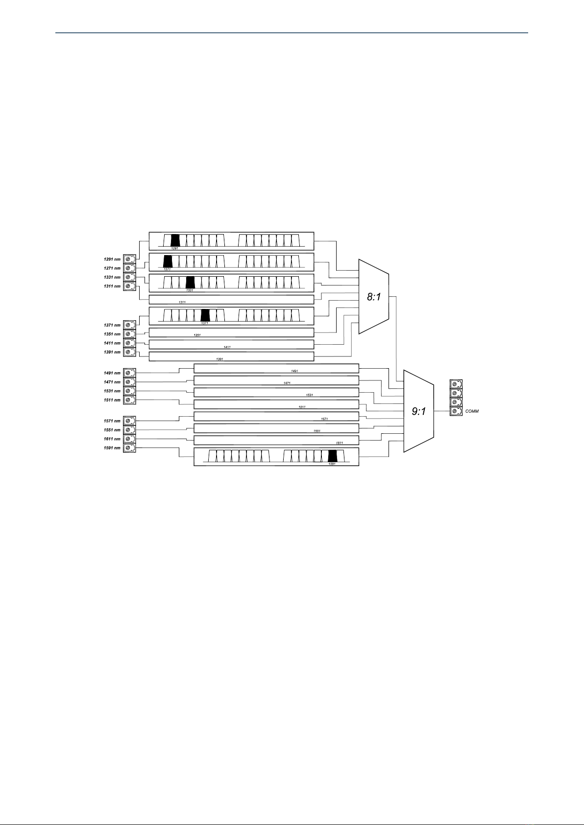
1.3. Block diagram .................................................................................................................................. 7
2. SPECIFICATIONS ................................................................................................................. 9
3. INSTALLATION .................................................................................................................. 11
3.1. Initial inspection .......................................................................................................................... 11
3.2. Safety instructions ...................................................................................................................... 11
3.3. Environmental considerations ................................................................................................ 12
3.4. Installing the module in the mounting frame ................................................................... 12
3.5. Interconnection ............................................................................................................................ 13
3.5.1. Optical SDI video connections ........................................................................................ 13
4. OPERATION ...................................................................................................................... 15
4.1. Functional description ............................................................................................................... 15
4.2. Module remote control and supervision ............................................................................. 16
5. GLOSSARY ........................................................................................................................ 19
6. REGULATIONS .................................................................................................................. 21
7. VERSIONS ......................................................................................................................... 23

CWS2016C01

Albalá Ingenieros | Manual CWS2016C01
1. DESCRIPTION
1.1. The CWS2016C01
The CWS2016C01 is a multiplexer/demultiplexer module for optical signal wavelengths
to/from a single fiber optic cable that operates as per ITU-T G.694.2 (CWDM).
The CWS2016C01 uses low-loss optical micro-hybrid technology for optical signals. Its
miniaturized hermetic capsule guarantees reliable, long-lasting operation
The CWS2016C01 is bi-directional and can be used as a multiplexer or demultiplexer.
The CWS2016C01 is a completely passive product that does not require external energy.
However, it does contain a microprocessor via which the model number, serial number
and position in a mounting frame can all be verified.
Albalá Ingenieros manufactures an electrical-to-optical port, the EOP2000, that together
with the CWS2016C01 can be used to create an access point via a sole fiber optic cable
for multiple electrical format digital video signals in a single 2 RU 19'' rack mounting
frame.
The CWS2016C01 fits into two slots of the mounting frame in which it is housed.
The CWS2016C01 is a TL2000 terminal line module and can be housed in a two rack unit
(2 RU) UR2000 mounting frame.
The CWS20XX family includes several multiplexers/demultiplexers for optical signals.
The following variations are available:
• CWS2008C01: An optical multiplexer/demultiplexer for eight channels of CWDM.
• CWS2009C01: An optical multiplexer/demultiplexer for nine channels of CWDM.
• CWS2016C01: An optical multiplexer/demultiplexer for 16 channels of CWDM.
5

Albalá Ingenieros | Manual CWS2016C01
1.2. Features
• Passive optical multiplexer or demultiplexer
• Each optical connection can function as an input or as an output.
• Manages 16 grid wavelengths as per ITU-T G.694.2.
• One sole optical connection for the multiplexed signal.
• Low insertion losses for each wavelength.
• LC-PC connectors available via spring-loaded shutter.
• Compact, occupies two slots of a UR2000 mounting frame.
6

Albalá Ingenieros | Manual CWS2016C01
1.3. Block diagram
7

Albalá Ingenieros | Manual CWS2016C01
CWS2016C01
8

Albalá Ingenieros | Manual CWS2016C01
2. SPECIFICATIONS
Optical
Connector LC/PC with multimode or monomode
fiber
Return loss >45 dB
Operating wavelength 1271, 1291, 1311, 1331, 1351, 1371,
1391, 1411, 1471, 1491, 1511, 1531,
1551, 1571, 1591 y 1611 nm
Bandwidth >13 nm (0,5dB)
Insertion loss:
Typical <3.0 dB
Maximum <5.5dB from 1271 nm to 1411nm
<3.5dB from 1471 nm to 1611 nm
Adjacent channel isolatation >30 dB
Directivity >50 dB
Maximum power at the input:
Acting as a multiplexer 0 dBm
+ 10 dBm
General
Operating temperature range 0 .. 60 °C
Approximate weight 400 g
9

Albalá Ingenieros | Manual CWS2016C01
CWS2016C01
10

Albalá Ingenieros | Manual CWS2016C01
3. INSTALLATION
THE CWS2016C01 MODULE CONTAINS ELECTRONIC DEVICES SENSITIVE TO
ELECTROSTATIC DISCHARGE. Always use antistatic bags clearly identified
with a high degree of shielding for storage and transportation.
3.1. Initial inspection
Verify that the package has been properly handled during transport. After opening the
packaging, check that the CWS2016C01 module is inside.
You must notify your Albalá Ingenieros distributor or dealer of any damage or defects
observed.
Follow the instructions in this manual to install this module in the mounting frame.
3.2. Safety instructions
•If the CWS2016C01 is used as a multiplexer of optical signals with
wavelengths between 1250 and 1650 nm, the optical power at its output is
the sum of the optical powers of all the contributing signals. If the
CWS2016C01 receives optical signals from Class 1 sources at each one of its
inputs as per IEC 60825-1 then the optical output may exceed the limit set
by Class 1.
•If the CWS2016C01 is used as a multiplexer of optical signals with
wavelengths between 1250 and 1650 nm, the optical power of each
individual input signal should not exceed 0dBm. When the CWS2016C01
manages contributing optical signals with optical powers less than 0dBm,
the CWS2016C01 can be operated with the same considerations as a CLASS
1 LASER product.
•If the CWS2016C01 is used as a demultiplexer with optical signals whose
wavelength is between 1250 and 1650 nm, the optical power at the input
should not exceed +10dBm. When the optical power at the input is less
than +10dBm, the CWS2016C01 can be operated with the considerations
as a CLASS 1 LASER product.
•Use CAUTION as the fiber optic connectors of the module emit invisible
laser radiation. Avoid exposure to the beam. NEVER lift or remove the
end-cap of the fiber optic connectors of the CWS2016C01 except when
connecting a cable and, when doing so, make sure that all sources of the
fiber optic signals are off. NEVER leave fiber optic cables carrying signals
11

Albalá Ingenieros | Manual CWS2016C01
unconnected. NEVER examine a fiber optic cable with a microscope or a
magnifying glass with making absolutely sure that they do not carry any
optical signal - otherwise severe retinal damage can occur.
•All of the fiber optic connectors are located on the front pane of the module,
covered by removable end-caps and marked with the yellow triangle symbol
indicating laser radiation for those connectors that may emit invisible laser
radiation.
•The CWS2016C01 module and the mounting frame should always be
installed, maintained, operated and removed by personnel with sufficient
technical qualifications. The equipment should never be placed in damp
areas, near splashing liquid, or in explosive or corrosive atmospheres.
Neither modules nor mounting frames can be used in applications that
could endanger human life.
3.3. Environmental considerations
This symbol indicates that this equipment must be deposited at a collection
point for proper waste treatment once it has reached the end of its useful
life.
3.4. Installing the module in the mounting frame
The following steps should be followed in order to install a CWS2016C01 module in the
mounting frame.
1 - Remove the cover panel at the front of the selected slot and the slot directly to the
right in order to install the CWS2016C01 into the mounting frame.
2 - Insert the CWS2016C01 module into the front of the mounting frame. The edges of
the card slide into two plastic guides inside the mounting frame.
3 - Secure the module to the mounting frame using the two front screws.
After these steps, the module is ready to be connected to other equipment.
12

Albalá Ingenieros | Manual CWS2016C01
3.5. Interconnection
The arrangement of the front panel connectors of the CWS2016C01 module is shown in
the following figure.
Front panel of the CWS2016C01
The optical connectors that provide access to the multiplexer/demultiplexer at LC/PC
type. A label above each connector details the corresponding wavelength in nanometers.
The connector marked COMM is the signal input destined for demultiplexing or is the
output of the multiplexed signal. The connectors labeled SP-1,SP-2 and SP-3 are not
used.
The front panel has not been designed to support mechanical stress. All cabling in the
rack where the mounting frame is located should be properly supported so that the front
panel does not provide mechanical support.
3.5.1. Optical SDI video connections
Singlemode fiber must be used in fiber optic cabling. However, for standard definition
and short lengths multimode fiber can be employed. Before connecting any fiber
optics, the cap that protects the connectors should be lifted. Unused fiber optic
connectors should always be covered by the protective cap.
All fiber optic cables have a minimum curvature radius that must be obeyed (consult
the specification of the cabling used) and should be run with enough strain relief to
absorb small, unintended pulling or mechanical stress.
13

Albalá Ingenieros | Manual CWS2016C01
The minimum radius for any curvature in typical fiber optic cabling (ITU-T G.652) is
normally 30mm. If smaller radius are required, then reduced radius cabling should be
used (ITU-T G.657).
14

Albalá Ingenieros | Manual CWS2016C01
4. OPERATION
4.1. Functional description
The CWS2016C01 is a passive device that does not need an external energy input.
However, for the purpose of inventory it contains a small electronic circuit for
verification of the product code, serial number and its position in the mounting frame.
This information can only be read wen a communications controller is installed in the
same mounting frame.
The connections to the CWS2016C01 are selective with regards to wavelength with the
exception of the common port (COMM). Each contributing input or output includes an
optical band-pass filter whose center frequency is displayed in a label for each
connector. Each of these contributing wavelengths can be optical signal inputs or
outputs independently of the access direction of the other wavelengths.
The connector labeled COMM transfers the multiplexed optical signal to the central fiber
optic cable. The central fiber optic cable should be connected to the COMM input of a
CWS2016C01, CWS2009C01 or CWS2008C01 at both ends.
The connectors labeled SP-1,SP-2 and SP-3 are not used.
In order to pass the signal received at a connector to the central fiber optic cable its
wavelength must correspond to the value stated in the label just above the connector. It
is not necessary to have all of the optical connectors of the module connected to fiber
optic cables.
When the CWS2016C01 is used to multiplex various fiber optic cables, its COMM
connector outputs the sum of the optical signals at the inputs, and each input
experiences a slight attenuation. When used as a demultiplexer the signal coming into
COMM should contain multiple wavelengths that are distributed to each of the outputs
based upon their signal wavelength, each with a slight attenuation.
Regardless of the multiplexing mode, the attenuation from the input port to the output
port differs for each wavelength and the specific value for each one will be within the
values given in the specifications section of this manual.
15

Albalá Ingenieros | Manual CWS2016C01
HUB/SWITCH
TL2000
COMMUNICATIONS
CONTROLLER MODULE
OTHER TL2000
MODULES
Ethernet
Ethernet
Ethernet
Ethernet
REMOTE CONTROL UNIT
TLE2001 PSU2000 PSU2000
UR2000 INTERNAL BUS
UR2000 INTERNAL BUS
Module remote control and supervision
4.2. Module remote control and supervision
The CWS2016C01 can optionally be remotely controlled/supervised.
In order to perform remote configuration and supervision of the module an optional
TL2000 family remote communications controller must be installed in the mounting
frame.
The main function of the communications control module is to interface between a
10/100 Ethernet port and the internal bus of the mounting frame. The following
illustration shows the most common control situations: from a computer or control
panel via Ethernet.
Certain communications control modules provide additional, more advanced functions
such as an SNMP agent, logging of status changes of the modules and a Web interface
for remote control, etc.
Software for simple configuration and supervision with a GUI for multiple modules can
be downloaded from the Albalá Ingenieros website.
The only remote function that can be performed with the CWS2016C01 is identification
of the model number and the serial number.
16

Albalá Ingenieros | Manual CWS2016C01
VERSION 1.X
17

Albalá Ingenieros | Manual CWS2016C01
CWS2016C01
18

Albalá Ingenieros | Manual CWS2016C01
5. GLOSSARY
SFP
Small Form-factor Pluggable. A specification that defines the size, format and electrical
characteristics of a class of modules typically employed to convert data signals from
electrical to optical format, from optical to electrical format and transmission of those
signal over fiber optics.
SFP+
Small Form-factor Pluggable. A specification that defines the size, format and electrical
characteristics of a class of modules typically employed to convert data signals from
electrical to optical format, from optical to electrical format and transmission of those
signal over fiber optics. Physically it is identical to SFP but can work with signals of a
higher bitrate up to 12Gbit/s.
19

Albalá Ingenieros | Manual CWS2016C01
CWS2016C01
20
Table of contents
Other Albalá Ingenieros Recording Equipment manuals