Albemarle 410 CONVERTIBLE User manual

41 CONVERTIBLE
Albemarle Boats
140 Midway DR.
P.O. Box 349
Edenton, NC 27932
OWNER’S MANUAL

410 Convertible
2
Print Date 6/2006
THIS PAGE WAS LEFT BLANK
INTENTIONALLY

3
410 Convertible
SAFETY INFORMATION
Your Albemarle manual has been written to include a number of safety instructions to assure the safe operation and maintenance
of your boat. These instructions are in the form of DANGER, WARNING, CAUTION, and NOTICE statements. The fol-
lowing definitions apply:
IMMEDIATE HAZARDS WHICH WILL RESULT IN
SEVERE PERSONAL INJURY OR DEATH.
HAZARDS OR UNSAFE PRACTICES WHICH
COULD RESULT IN SEVERE PERSONAL INJURY
OR DEATH.
HAZARDS OR UNSAFE PRACTICES WHICH
COULD RESULT IN MINOR PERSONAL INJURY OR
PRODUCT AND PROPERTY DAMAGE.
All instructions given in this book are as seen from the stern looking toward the bow, with starboard being to your right, and
port to your left. A glossary of boating terms is included.
IMPORTANT NOTE: Your boat uses internal combustion engines and flammable fuel. Every precaution has been taken
by Albemarle to reduce the risks associated with possible injury and damage from fire or explosion, but your own precaution
and good maintenance procedures are necessary in order to enjoy safe operation of your boat.

410 Convertible
4
BOAT INFORMATION
MAKE:
SERIAL #:
MODEL:
BTU OUTPUT:
PHONE:
REPRESENTATIVE:
AIR CONDITIONER
NAME:
DEALER/PHONE:
ADDRESS:
SERVICE MANAGER:
ADDRESS:
SALESMAN:
DEALER ALBEMARLE
MODEL:
PURCHASE DATE:
IGNITION KEYS #:
DRAFT:
HULL SERIAL #:
DELIVERY DATE:
REGISTRATION #:
WEIGHT:
TRANSMISSIONS
GENERATOR
MAKE:
PORT SERIAL #:
MODEL:
STARBOARD SERIAL #:
PORT SERIAL #:
MAKE: MODEL:
STARBOARD SERIAL #:
PROPELLERS
MAKE: MODEL:
KILOWATTS:
MAKE:
DIAMETER/PITCH:
SERIAL #:
RATIO:
ENGINES
BLADES:
SHAFT:
BOAT
Albemarle reserves the right to make changes and improvements in equipment, design and vendored equipment
items, at any time without notification.
Please fill out the following information section and leave it in your Albemarle owner’s manual. This information
will be important for you and Albemarle service personnel to know, if you may need to call them for technical
assistance or service.
ALBEMARLE E-MAIL:
DEALER E-MAIL:
BEAM: VERTICAL CLEARANCE:
DOOR KEYS:

5
410 Convertible
CERTIFICATIONS & SPECIFICATIONS
(For Export Only)
Manufacturer:
Name
Address
Zip Code:
Identification Numbers:
Hull Identification Number
Port Engine Serial Number
Starboard Engine Serial Number
Intended Design Category:
Ocean Inshore
Offshore Sheltered Waters
Weight and Maximum Capacities:
Unladen Weight - Kilograms (Pounds)
Maximum Load - Weight- Kilograms (Pounds)
Number of People
Maximum Rated Engine Horsepower - Kilowatts (Horsepower)
Certifications:
Certifications & Components Covered
To be in compliance with European directives for recreational boats as published by the International Organiza-
tion for Standardization (ISO) in effect at the time this boat was manufactured, we are providing the following
information.

410 Convertible
6
THIS PAGE WAS LEFT BLANK
INTENTIONALLY

7
410 Convertible
All instructions given in this book are as seen from the stern
looking toward the bow with starboard being to your right, and
port to your left. The information and precautions listed in
this manual are not all inclusive. It may be general in nature
in some cases and detailed in others. The suppliers of some
of the major components such as engines, pumps, and appli-
ances, provide their own owner’s manuals which have been
included with your boat. You should read the information in
this manual and the manuals of other suppliers completely and
have a thorough understanding of all component systems and
their proper operation before operating your boat.
REMEMBER - IT IS YOUR RESPONSIBILITY TO ENSURE
THAT YOUR BOAT IS SAFE FOR YOU AND YOUR PAS-
SENGERS. ALWAYS EXERCISE GOOD COMMON SENSE
WHEN INSTALLING EQUIPMENT AND OPERATING THE
BOAT.
Warranty and Warranty Registration Cards
The Albemarle Limited Warranty Statement is included with
your boat. It has been written to be clearly stated and eas-
ily understood. If you have any questions after reading the
warranty, please contact the Albemarle Customer Service
Department.
Albemarle, engine manufactures, and the suppliers of major
components maintain their own manufacturer’s warranty and
service facilities. It is important that you properly complete
the warranty registration cards included with your boat and
engine(s) and mail them back to the manufacturer to register
your ownership. This should be done within 15 days of the
date of purchase and before the boat is put into service. A form
for recording this information is provided at the beginning of
this manual. This information will be important for you and
service personnel to know, if and when you may need service
or technical information.
The boat warranty registration requires the Hull Identifica-
tion Number “HIN” which is located on the starboard side
of the transom, just below the rubrail. The engine warranty
registration requires the engine serial number(s). Please refer
to the engine owner’s manual for the location of the serial
number(s).
IMPORTANT:
All boat manufacturers are required by the Federal Boat Safety
Act of 1971 to notify first time owners in the event any defect is
discovered “which creates a substantial risk of personal injury
to the public.” It is essential that we have your warranty
registration card complete with your name and mailing
address in our files so that we can comply with the law if it
should become necessary.
Product Changes
Albemarle is committed to the continuous improvement of our
boats. As a result, some of the equipment described in this
manual or pictured in the catalog may change or no longer be
available. Albemarle reserves the right to change standard
equipment, optional equipment and specifications without
notice or obligation. If you have questions about the equip-
ment on your Albemarle, please contact the Albemarle Cus-
tomer Service Department.
Service
All warranty repairs must be performed by an authorized
Albemarle Dealer. Should a problem develop that is related to
faulty workmanship or materials, as stated in the Limited War-
ranty, you should contact your Albemarle dealer to arrange for
the necessary repair. If you are not near your dealer or another
authorized Albemarle dealer or the dealer fails to remedy the
cause of the problem, then contact Albemarle within 15 days.
It is the boat owner’s responsibility to deliver the boat to
the dealer for warranty service.
IMPORTANT INFORMATION

410 Convertible
8
THIS PAGE WAS LEFT BLANK
INTENTIONALLY

9
410 Convertible
Registration and Numbering
Federal law requires that all undocumented vessels equipped
with propulsion machinery be registered in the State of principal
use. A certificate of number will be issued upon registering
the boat. These numbers must be displayed on your boat. The
owner/operator of a boat must carry a valid certificate of number
whenever the boat is in use. When moved to a new State of
principal use, the certificate is valid for 60 days.
In order to be valid, the numbers must be installed to the
proper specifications. Check with your dealer or state boat-
ing authority for numbering requirements. The Coast Guard
issues the certificate of number in Alaska; all others are issued
by the state.
Insurance
In most States the boat owner is legally responsible for dam-
ages or injuries he or someone else operating the boat causes.
Responsible boaters carry adequate liability and property
damage insurance for their boat. You should also protect the
boat against physical damage and theft. Some States have laws
requiring minimum insurance coverage. Contact your dealer
or State boating authority for information on the insurance
requirements in your boating area.
Reporting Boating accidents
All boating accidents must be reported by the operator or owner
of the boat to the proper marine law enforcement authority for
the state in which the accident occurred. Immediate notifica-
tion is required if a person dies or disappears as a result of a
recreational boating accident.
If a person dies or there are injuries requiring more than first
aid, a formal report must be filed within 48 hours.
A formal report must be made within 10 days for accidents
involving more than $500.00 damage or the complete loss of
a boat.
A Boating Accident Report form is located near the back of
this manual to assist you in reporting an accident. If you need
additional information regarding accident reporting, please call
the Boating Safety Hotline, 800-368-5647.
Education
If you are not an experienced boater, we recommend that the
boat operator and other people that normally accompanies the
operator, enroll in a boating safety course. Organizations such
as the U.S. Power Squadrons, United States Coast Guard Aux-
iliary, State Boating Authorities and the American Red Cross
offer excellent boating educational programs. These courses
are worthwhile even for experienced boaters to sharpen your
skills or bring you up to date on current rules and regulations.
They can also help in providing local navigational information
when moving to a new boating area. Contact your dealer, State
Boating Authority or the Boating Safety Hotline, 800-368-5647
for further information on boating safety courses.
Required Equipment
U.S. Coast Guard regulations require certain equipment on each
boat. The Coast Guard also sets minimum safety standards for
vessels and associated equipment. To meet these standards
some of the equipment must be Coast Guard approved. “Coast
Guard Approved Equipment” has been determined to be in
compliance with USCG specifications and regulations relating
to performance, construction, or materials. The equipment
requirements vary according to the length, type of boat, and
the propulsion system. Some of the Coast Guard equipment
is described in the Safety Equipment chapter of this manual.
For a more detailed description, obtain “Federal Requirements
And Safety Tips For Recreational Boats” by contacting the
Boating Safety Hotline 800-368-5647 or your local marine
dealer or retailer.
Some state and local agencies impose similar equipment re-
quirements on waters that do not fall under Coast Guard juris-
diction. These agencies may also require additional equipment
that is not required by the Coast Guard. Your dealer or local
boating authority can provide you with additional information
for the equipment requirements for your boating area.
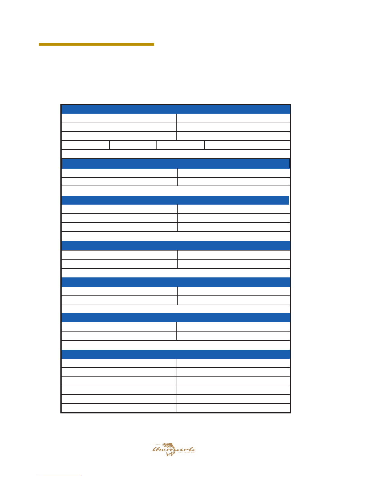
OWNER’S / OPERATOR’S INFORMATION

410 Convertible
10
THIS PAGE WAS LEFT BLANK
INTENTIONALLY

11
410 Convertible
TABLE OF CONTENTS
Chapter 1:
PROPULSION SYSTEM
1.1 General ................................................................................................................................................................................ 15
1.2 Drive Systems ....................................................................................................................................................................... 15
1.3 Engine Exhaust System ........................................................................................................................................................ 15
1.4 Engine Cooling System ........................................................................................................................................................ 15
1.5 Oil Change Pump ................................................................................................................................................................. 16
1.6 Propellers ............................................................................................................................................................................. 17
1.7 Running Gear ....................................................................................................................................................................... 18
1.8 Engine Instrumentation ....................................................................................................................................................... 19
Chapter 2:
HELM CONTROL SYSTEMS
2.1 General ................................................................................................................................................................................ 21
2.2 Engine Throttle and Shift Controls ...................................................................................................................................... 21
2.3 Engine Synchronizer ........................................................................................................................................................... 22
2.4 Neutral Safety Switch ........................................................................................................................................................... 22
2.5 Steering System .................................................................................................................................................................... 22
2.6 Trim Tabs ............................................................................................................................................................................ 23
2.7 Control Systems Maintenance ............................................................................................................................................. 23
Chapter 3:
FUEL SYSTEM
3.1 General ................................................................................................................................................................................ 27
3.2 Diesel Engine Fuel System .................................................................................................................................................. 28
3.3 Generator Fuel System ........................................................................................................................................................ 28
3.4 Fueling Instructions ............................................................................................................................................................. 29
3.5 Fuel System Maintenance .................................................................................................................................................... 29
Chapter 4:
ELECTRICAL SYSTEM
4.1 General ................................................................................................................................................................................ 31
4.2 12-Volt System ...................................................................................................................................................................... 31
4.3 240 and 120-Volt System ...................................................................................................................................................... 38
4.4 Generator .............................................................................................................................................................................. 41
4.5 Bonding System ..................................................................................................................................................................... 42
4.6 Electrical System Maintenance ............................................................................................................................................ 42
Chapter 5:
FRESH WATER SYSTEM
5.1 General ................................................................................................................................................................................ 45
5.2 Fresh Water System Operation ............................................................................................................................................. 45
5.3 Water Heater ....................................................................................................................................................................... 46
5.4 City Water Connection (Optional) ....................................................................................................................................... 46
5.5 Shower Operation ................................................................................................................................................................ 46

410 Convertible
12
Chapter 5:
FRESH WATER SYSTEM (Continued)
5.6 Reverse Osmosis Filter (Optional) ...................................................................................................................................... 47
5.7 Fresh Water System Maintenance ........................................................................................................................................ 47
Chapter 6:
RAW WATER SYSTEM
6.1 General ................................................................................................................................................................................ 49
6.2 High Pressure Washdown ................................................................................................................................................... 49
6.3 Livewell ............................................................................................................................................................................... 50
6.4 Air Conditioning and Optional Freezer ............................................................................................................................... 50
6.5 Raw Water System Maintenance .......................................................................................................................................... 51
Chapter 7:
DRAINAGE SYSTEMS
7.1 General ................................................................................................................................................................................ 53
7.2 Hard Top or Tower Drains (Optional) ................................................................................................................................ 53
7.3 Bilge Drainage and High Water Alarms .............................................................................................................................. 53
7.4 Cockpit and Deck Drains ..................................................................................................................................................... 54
7.5 Cabin Drains ....................................................................................................................................................................... 54
7.6 Drainage System Maintenance ............................................................................................................................................ 55
Chapter 8:
VENTILATION SYSTEM
8.1 Cabin Ventilation ................................................................................................................................................................. 57
8.2 Carbon Monoxide and Proper Ventilation .......................................................................................................................... 57
8.3 Engine Compartment Ventilation ......................................................................................................................................... 58
8.4 Maintenance ........................................................................................................................................................................ 59
Chapter 9:
EXTERIOR EQUIPMENT
9.1 Deck .................................................................................................................................................................................... 61
9.2 Hull ..................................................................................................................................................................................... 62
9.3 Cockpit ............................................................................................................................................................................... 62
9.4 Flybridge and Helm ............................................................................................................................................................. 65
9.5 Half Tower and Tuna Tower ................................................................................................................................................. 67
Chapter 10:
INTERIOR EQUIPMENT
10.1 Head Compartment & Marine Toilet ................................................................................................................................. 69
10.2 Galley ................................................................................................................................................................................ 70
10.3 Main Salon ......................................................................................................................................................................... 71
10.4 Cabin Air Conditioners ...................................................................................................................................................... 72
10.5 Second Stateroom ............................................................................................................................................................... 73
TABLE OF CONTENTS

13
410 Convertible
Chapter 10:
INTERIOR EQUIPMENT
10.6 Master Stateroom ............................................................................................................................................................... 73
10.7 Cabin Woodwork ................................................................................................................................................................ 74
Chapter 11:
SAFETY EQUIPMENT
11.1 General .............................................................................................................................................................................. 75
11.2 Engine Alarms ................................................................................................................................................................... 75
11.3 Neutral Safety Switch ......................................................................................................................................................... 75
11.4 Required Safety Equipment ................................................................................................................................................ 75
11.5 Automatic Fire Extinguishing System ............................................................................................................................... 77
11.6 Carbon Monoxide Monitoring System .............................................................................................................................. 78
11.7 First Aid ............................................................................................................................................................................. 79
11.8 Additional Safety Equipment .............................................................................................................................................. 79
11.9 Caution and Warning Labels ............................................................................................................................................. 80
Chapter 12:
OPERATION
12.1 General .............................................................................................................................................................................. 81
12.2 Rules of the Road ............................................................................................................................................................... 81
12.3 Pre-Cruise Check ............................................................................................................................................................... 83
12.4 Operating Your Boat .......................................................................................................................................................... 83
12.5 Docking, Anchoring and Mooring .................................................................................................................................... 85
12.6 Controls, Steering, or Propulsion System Failure: ............................................................................................................ 86
12.7 Collision ............................................................................................................................................................................. 86
12.8 Grounding, Towing and Rendering Assistance .................................................................................................................. 87
12.9 Flooding, or Capsizing ...................................................................................................................................................... 87
12.10 Fishing ............................................................................................................................................................................. 87
12.11 Man Overboard ................................................................................................................................................................ 87
12.12 Tower Operation (Optional) ............................................................................................................................................ 88
12.13 Trash Disposal ................................................................................................................................................................. 89
12.14 Transporting Your Boat .................................................................................................................................................... 89
Chapter 13:
ROUTINE MAINTENANCE
13.1 Exterior Hull and Deck ...................................................................................................................................................... 91
13.2 Upholstery, Canvas and Enclosures .................................................................................................................................. 93
13.3 Cabin Interior .................................................................................................................................................................... 94
13.4 Bilge and Engine Compartment ......................................................................................................................................... 94
13.5 Drainage System ................................................................................................................................................................ 95
TABLE OF CONTENTS

410 Convertible
14
Chapter 14:
SEASONAL MAINTENANCE
14.1 Lay-up and Storage ............................................................................................................................................................. 97
14.2 Winterizing .......................................................................................................................................................................... 98
14.3 Recommissioning .............................................................................................................................................................. 100
Appendix A:
SCHEMATICS
Rudder Assembly ....................................................................................................................................................................... 115
Coupler Assembly ..................................................................................................................................................................... 115
Shaft Seal Assembly .................................................................................................................................................................. 116
Prop Assembly ........................................................................................................................................................................... 116
Appendix B:
GENERAL MAINTENANCE SCHEDULE AND LOG .......................................................................................... 119
Appendix C:
FLOAT PLAN....................................................................................................................................................................... 125
Appendix D:
BOATING ACCIDENT REPORT .................................................................................................................................. 128
Appendix E:
GLOSSARY OF TERMS ................................................................................................................................................. 129
Appendix F:
TROUBLESHOOTING GUIDE ..................................................................................................................................... 133
TABLE OF CONTENTS

15
410 Convertible
Chapter 1:
PROPULSION SYSTEM
1.1 General
The Albemarle 41 Convertible is designed to be powered with
twin diesel inboard engines. Each manufacturer of the various
marine power components provides an owner’s information
manual with their product. It is important that you read the
manuals very carefully and become familiar with the proper
care and operation of the engines and drive system. A warranty
registration card has been furnished with each new engine and
can be located in the engine owner’s manual. All information
requested on this card should be filled out completely by the
dealer and purchaser and then returned to the respective engine
manufacturer as soon as possible.
DO NOT ATTEMPT TO SERVICE ANY ENGINE OR
DRIVE COMPONENT WITHOUT BEING TOTALLY
FAMILIAR WITH THE SAFE AND PROPER SERVICE
PROCEDURES. CERTAIN MOVING PARTS ARE
EXPOSED AND CAN PROVE DANGEROUS TO
SOMEONE UNFAMILIAR WITH THE OPERATION
AND FUNCTION OF THE EQUIPMENT.
1.2 Drive Systems
On inboard propulsion systems, all shifting and gearing com-
ponents are installed inside the hull. Only the propeller shafts
and associated equipment are under water. The engines are
mounted below the cabin floor. A transmission, also called a
gearbox, which performs desired shifting functions, is directly
coupled to each engine. The propeller shaft extends through
the hull and connects the transmission output coupling with the
propeller. The transmissions have built-in reduction gearing.
This gearing reduces the speed of the propeller in relation to
engine speed.
ALWAYS RETURN THE ENGINE THROTTLE LEVERS
TO THE EXTREME LOW SPEED POSITION BEFORE
SHIFTING. NEVER SHIFT THE UNIT WHILE THE
ENGINE SPEED IS ABOVE 1000 RPM.
All transmissions require oil or fluid of some type for lubrica-
tion. This level should be checked at the same interval as the
engine oil level.
Your boat is equipped with transmissions supplied by the en-
gine manufacturer. For details on the transmissions, refer to
the engine or transmission owner’s manual.
1.3 Engine Exhaust System
Engine exhaust exits the rear of the boat through the exhaust
system. The system consists of engine exhaust manifolds,
exhaust hoses, mufflers, and thru-hull exhaust fittings.
Inboard boats use the exhaust system to expel exhaust gases
and cooling water. A periodic inspection of the hoses, muf-
flers and related parts should be made to ensure that leaks or
heat deterioration have not resulted. Periodically inspect these
items for signs of deterioration or damage. Replace them as
necessary.
DO NOT INHALE EXHAUST FUMES! EXHAUST
CONTAINS CARBON MONOXIDE THAT
IS COLORLESS AND ODORLESS. CARBON
MONOXIDE IS A DANGEROUS GAS THAT IS
POTENTIALLY LETHAL.
1.4 Engine Cooling System
All marine engines use surface water as a cooling medium.
The cooling water enters the system through a water intake in
the hull and is expelled through the exhaust system. Water is
pumped through the water inlets, circulated through the engine
block or heat exchanger, and relinquished with the exhaust
gases through the exhaust system. The water pump uses a small
impeller made of synthetic rubber. The impeller and water
pump cannot run dry for more than a few seconds.
Propulsion System

410 Convertible
16
Inboard engines use a thru-hull water intake scoop and strainer.
This strainer is located on the hull bottom and must be kept
free of mud, weeds and other debris. A ball valve is provided
on each intake thru-hull. Be sure these valves are in the open
position before operating the boat engines.
The strainers should be visually inspected each time the boat
is hauled for accumulation of marine growth, weeds, and
other foreign objects. If clogged or dirty, the strainer should
be cleaned.
A CLOGGED SEA STRAINER CAN RESTRICT THE
SUPPLY OF COOLING WATER TO THE ENGINE AND
EXHAUST COMPONENTS, WHICH COULD RESULT
IN SEVERE ENGINE AND EXHAUST SYSTEM
DAMAGE.
Cleaning the sea strainers
• Make sure the boat is properly blocked and supported.
• Remove the safety ring and clevis pin at the rear of the
strainer.
• Open the access door and remove debris or marine growth.
Thoroughly flush the screen and the inside of the strainer
to remove foreign matter.
• Close the access door and install the clevis pin and safety
ring.
SHOULD AN ENGINE INTAKE, EXHAUST OR
COOLING HOSE RUPTURE, TURN OFF THE
ENGINE AND CLOSE THE ENGINE WATER INTAKE
VALVE IMMEDIATELY. PROCEED, UNDER TOW
IF NECESSARY, TO A SERVICE FACILITY FOR
APPROPRIATE REPAIRS. MAINTAIN A CLOSE
VISUAL WATCH ON THE PROBLEM HOSE AND THE
BILGE WATER LEVEL.
Inboard boats utilize an exhaust hose to relinquish cooling
water. A periodic inspection of the hose, mufflers and related
parts should be made to ensure that leaks or heat deterioration
have not resulted.
A “freshwater” or “closed” cooling system that is cooled by
a heat exchanger and the seawater cooling system provides
adequate engine cooling without exposing the internal engine
cooling system to the harmful effects of surface water. This
system is standard with all diesel engines. The engine owner’s
manual provides additional information regarding the service
and maintenance of this equipment.
1.5 Oil Change Pump
Your boat is equipped with an oil change pump system designed
to change and fill the engine oil in the main engines and the
generator. It is mounted in the engine compartment aft of the
starboard engine.
The system is designed with a manifold system that enables one
pump to service multiple engines. Oil hoses are run from the
engine oil pan fitting directly to valves on the manifold. The
valves are labeled and are used select the engine to be serviced.
The reversible pump is controlled by a switch near the valves.
In one direction it will pump oil out of the engines. In the other
direction it will pump fresh oil into the engines.
Draining Oil from Engines
Place the drain/ fill hose in an empty container. Open the valve
on the manifold which connects to the engine to be serviced.
Switch the pump to draw oil from the engine. (Push the switch
away from manifold) Repeat this process for each engine or
generator to be serviced.
External Engine Sea Strainer
Engine Oil Change System

17
410 Convertible
Filling/ Adding Oil to Engine(s):
Place the drain/ fill hose into a container of new oil. Open
the valve on the manifold which connects to the engine to be
serviced. Switch the pump to draw oil from the new oil con-
tainer. (Push the switch toward the manifold) NOTE: Operate
pump with only one valve open at a time. Be sure that a valve
is open prior to pump operation. Be sure to close all valves
when oil change is completed. (Handle pointed down - valve
open) (Handle pointed to the side - valve closed)
Refer to the oil change system owner’s manual for specific
information on the system installed in you boat. It is important
that you completely understand the operation of the pump and
valves before using the system.
1.6 Propellers
When the boats are shipped, the propellers are factory installed.
Should it be necessary to change propellers, always use an ap-
propriate removal tool or “Prop Puller.” Do not attempt removal
using a hammer. Damage to the propeller, propeller shaft, or
transmission can result.
A few simple steps will enable you to install a propeller. First,
make sure that no burrs or rough edges exist on the shaft, key,
and both keyways. Try the key into the keyways. It must
slide freely into position without having side play. It might
be necessary to file the key with a flat file to create the correct
tolerance.
To ensure the proper fit of your propeller, follow these pro-
cedures:
Step 1: Without the key installed, slip the propeller on the
shaft by hand as far as it will go. Mark the location
at the front of the hub with a dry-marker and remove
the propeller.
Step 2: Install the key in the shaft.
Step 3: Again, slide the propeller into position by hand.
Please note that the key should not extend beyond
the forward edge of the propeller hub. The propel-
ler should reach the same spot as before. If it does
not, the key has probably moved up the keyway, or
the key does not fit properly in one or both of the
keyways.
Step 4: Install the propeller nuts. When installing the shaft
nuts, take care not to tighten them too much. Do not
force the nut into a tighter position by using a ham-
mer or extension on the arm of the wrench. Tighten
the thin nut, then lock the wide nut tight against the
thin nut and insert the cotter pin.
If not properly installed, the propeller will be off balance and
this is a frequent cause of vibration. It could also cause the
propeller hub to split.
DO NOT ATTEMPT TO OPERATE THE BOAT IF THE
PROPELLER DOES NOT FIT PROPERLY ON THE
SHAFT. PROBLEMS SUCH AS SHAFT VIBRATION,
PROPELLER HUB FAILURE OR SHAFT FAILURE
MAY OCCUR.
Your boat was shipped with propellers that typically provide
optimum performance for your boat. However there are fac-
tors that can affect performance and propeller requirements.
Some are as follows:
• It is extremely important that the boat is propped to run at
or very near the recommended top RPM with an average
load. If the top RPM is above or below the recommend
range, the propellers must be changed to prevent loss of
performance and possible engine damage.
• Large diesel engines can be damaged and the warranty
void if the boat is not propped correctly. Always consult
your Albemarle or authorized engine service dealer when
making changes to the propellers or if the boat does not
run near the top recommended RPM.
• The addition of a Marlin or Tuna tower, heavy equipment
like life rafts, personal water craft, additional coolers,
etc., can will cause additional load on the engines.
Consequently, different propellers will be required.
Propeller Installation

410 Convertible
18
• Before changing propellers to correct boat performance
problems, be sure other factors such as engine tuning,
bottom and running gear growth, etc., are not the source
of performance changes. You also should be sure the load
conditions are those normally experienced. If the boat
ran in the required RPM range when it was new and you
have not added any additional gear or heavy equipment and
have not damaged the propellers, there is a good chance
the propellers are not the problem.
KEEP AWAY FROM THE PROPULSION MACHINERY
DURING ITS OPERATION OR WHENEVER THE
BOAT IS IN MOTION. MOVEMENT OF WATER PAST
A PROPELLER CAN CAUSE THE PROPELLER,
SHAFT AND OTHER PROPULSION MACHINERY TO
ROTATE EVEN IF THAT EQUIPMENT IS NOT BEING
OPERATED INTENTIONALLY.
1.7 Running Gear
Shaft Logs and Dripless Seal
The shaft logs, which are fastened into the hull bottom, allow
the propeller shaft to extend and rotate through the hull. The
shaft log is equipped with a special “Dripless” propeller shaft
seal. To lubricate this seal, sea water from the engine cooling
system is injected into the shaft seal through a hose that is
connected to the engine and the shaft seal housing.
The shaft seal must have positive water injection any time the
propeller shaft is rotating. The water flow to the seal should
be tested annually by removing the water injection hose from
the seal fitting and running the engine at idle with the trans-
mission in neutral. There should be a positive flow of water
from the hose. If no water is flowing from the hose, contact
your dealer or the Albemarle Customer Relations Department
before operating your boat. Some water will leak into the
bilge from the hose fitting on the seal assembly during this
test. The hose should immediately be reattached and the hose
clamps tightened securely when the test is completed. Please
refer to the seal manufacturer owner’s manual for additional
information on the shaft seal.
Proper performance of the shaft seal is directly dependent upon
correct propeller shaft alignment. Propeller damage, a bent strut
or shaft, or abnormal wear, settling, etc. are common reasons
for misalignment. This can cause such problems as repeated
shaft leakage, excess seal wear, shaft log and assembly damage,
premature strut bearing wear, etc. It is, therefore, important
that the alignment be periodically checked and adjustments are
made when necessary.
ALWAYS BE SURE TO USE THE SHAFT REMOVAL
SLEEVE AND FOLLOW THE SEAL MANUFACTURER’S
INSTRUCTIONS WHEN REMOVING OR INSTALLING
A PROPELLER SHAFT. IMPROPERLY REMOVING
OR INSTALLING A PROPELLER SHAFT CAN
PERMANENTLY DAMAGE THE SHAFT SEAL AND
CAUSE IT TO LEAK.
Struts
The struts are the metal castings bolted to the bottom of the
hull to secure the aft end of the propeller shafts. A replaceable
cutlass bearing, also called a strut bearing, is used to minimize
shaft wear. The strut bearing should be inspected once a year,
or whenever the boat is hauled, to ensure that there has been no
damage or deterioration and that the strut bearing is not worn
excessively. Upon inspection of the bearing, a small amount
of play between the propeller shaft and bearing, .008” to .010”,
is normal. This gap allows water to pass between the bearing
and the shaft to lubricate the bearing surface. If the rubber
bearing shows signs of deterioration or excessive wear, greater
than .015” play between the bearing and the shaft surfaces,
the bearing should be replaced and you should contact your
Albemarle dealer. It is advisable, during lay-up periods, to
insert some castor oil into the rubber bearing to keep it from
“freezing” to the shaft. Never use machine oil or grease on
the rubber bearing.
THE OPERATION OF THE BOAT IN HEAVILY
SILTED OR POLLUTED WATER, WITH A DAMAGED
PROPELLER, A DAMAGED PROPELLER SHAFT
OR WITH THE ENGINE OUT OF ALIGNMENT, CAN
SIGNIFICANTLY SHORTEN THE LIFE OF THE STRUT
BEARING. IF YOU EXPERIENCE ANY OF THESE
SITUATIONS, THE BEARING SHOULD BE CHECKED
MORE FREQUENTLY.
ALWAYS CHECK THE ENGINE ALIGNMENT AFTER
REPLACING THE STRUT BEARING.
Propeller Shaft Seal

19
410 Convertible
Propeller Shaft Alignment
The propeller shaft coupling and the transmission coupling
should be checked for proper alignment beginning with the first
launching, again after 20 hours of engine operation, and annu-
ally thereafter. The alignment should especially be checked if
noise or vibration occurs.
Excessive vibration, abnormal strut bearing wear, or broken
propeller shaft coupling bolts are an indication of misalignment.
Misalignment can also cause severe damage to the shaft log,
strut, shaft and the engine transmission. Realignment should
only be performed by a qualified service person.
The correct procedure for checking the shaft alignment so a
boat owner can determine if service work is required, is as
follows:
Step 1: Remove the bolts that secure the propeller shaft
flanges.
Step 2: Hold the propeller shaft flange firmly against the
transmission flange.
Step 3: Try to insert a .004” feeler gauge at the top, the
bottom and at both sides between the flanges. If
it can be easily inserted between the flanges in any
area, try inserting a larger feeler gauge until you
determine the amount of variance.
Step 4: While holding the transmission flange, turn the
prop shaft 90 degrees and repeat step 3. A straight
shaft in proper alignment will not allow the inser-
tion of a feeler gauge larger than .004”, regardless
of the prop shaft position.
Step 5: If a gap larger than .004” is found and the gap
moves as the shaft flange is rotated, the flange or
the prop shaft is bent out of tolerance and must
be replaced or removed and straightened. If the
gap remains at the same position regardless of the
propeller shaft rotated position, the engine must
be realigned. At this point, an Albemarle dealer
should be contacted.
NOTE: The boat should always be at rest in the water when
checking or aligning the propeller shaft.
MAKE SURE THE PROPELLER SHAFT FLANGE
BOLTS ARE TIGHTENED SECURELY AFTER
CHECKING THE ENGINE ALIGNMENT AND BEFORE
OPERATING THE BOAT.
Propeller Shaft Coupling
NOTE: Lifting the boat with lifting straps over the prop
shafts will cause the shafts to become bent. Always
position lifting straps so they are clear of the run-
ning gear.
1.8 Engine Instrumentation
The helm station is equipped with a set of engine instruments
and/or alarms. These instruments allow the pilot to monitor
the engine operational conditions. Close observation of these
instruments allows the pilot to operate the engines at the most
efficient level and could save the engines from serious costly
damage. The instrumentation is unique to the type of inboard
motors installed on your Albemarle and is typically built into
the electronic engine monitor and display system. Some or all
of the following gauges may be present.
Tachometer
The tachometer displays the speed of the engine in revolutions
per minute (RPM). This speed is not the boat speed nor nec-
essarily the speed of the propeller. The tachometer may not
register zero with the key in the “OFF” position.
Cat Marine Power Display (MPD)

410 Convertible
20
NEVER EXCEED THE MAXIMUM RECOMMENDED
OPERATION RPM OF THE ENGINE. MAINTAINING
MAXIMUM, OR CLOSE TO MAXIMUM RPM FOR
EXTENDED PERIODS CAN REDUCE THE LIFE OF
THE ENGINE.
Temperature Gauge
The temperature gauge indicates the temperature of the engine
cooling system. A sudden increase in the temperature could sig-
nal a blocked cooling passage or a water pump malfunction
CONTINUED OPERATION OF AN OVERHEATED
ENGINE CAN RESULT IN ENGINE SEIZURE. IF
AN UNUSUALLY HIGH TEMPERATURE READING
OCCURS, SHUT THE ENGINE OFF IMMEDIATELY.
THEN INVESTIGATE AND CORRECT THE
PROBLEM.
Oil Pressure Gauge
The oil pressure gauge monitors the engine lubrication system
pressure. The oil pressure indicated when the engine is new is
usually the reference for normal oil pressure for that engine.
A drop in oil pressure is a possible indication of oil pump
problems, a leak or fuel diluted oil..
Fuel Gauge
The fuel gauge indicates the amount of fuel in the fuel tank.
This gauge is merely a relative indication of the available fuel
supply and not a calibrated instrument.
Voltmeter
The voltmeter displays the voltage for the battery and the charg-
ing system. The normal voltage is 11 to 12.5 volts with the
engine off, and 13 to 14.5 volts with the engine running.
Hour Meter
The hour meter keeps a record of the operating time for the
engine. The hour meters are typically built into the engine
electronic monitor and display panel.
Rudder Position Indicator (Optional)
The rudder position indicator shows the current position of
the rudders. The rudder indicator gauge is not a calibrated
instrument and is intended to show the approximate position
of the rudders, primarily as a reference when maneuvering in
tight quarters. Wind and currents will cause a deviation in the
rudder indicator reading.
Depth Gauge (Optional)
The depth gauge indicates the depth of the water below the
bottom of the boat.
Fuel Management
Fuel management systems are optional and could be installed
on your boat. The fuel management gauge is used to moni-
tor the gallons per hour and also total gallons used. Some
fuel management systems are built into the engine electronic
monitor and display panels. If you have a fuel management
system installed on your boat, please refer to the engine or fuel
management manual for information on that system.
Engine Alarm
Most inboard engines are equipped with an audible alarm sys-
tem mounted in the helm area that monitors selected critical
engine systems. The alarm will sound if one of these systems
begins to fail. Refer to the engine owner’s manual for informa-
tion on the alarms installed with your engine.
If an engine alarm sounds, immediately shut off the engine
until the problem is found and corrected.
Cat Marine Power Display (MPD)
The Cat Marine Power Display for each engine is installed with
most Caterpillar engines. It is a simple to operate, self-con-
tained engine monitoring and display system that provides more
information to the operator than previously available engine
monitoring systems. It monitors RPM, oil pressure, coolant
temperature, battery voltage, turbo boost pressure, transmis-
sion temperature, transmission pressure, fuel consumption and
water in the fuel filter. If there is a problem with one of these
systems, it will sound an alarm and a diagnostic flag appears
on the screen until the problem is found and resolved.
A configuration screen and sealed control buttons allow the
operator to select different users, English or Metric units, and
the type of display format. Screen format options include
simulated gauge, digital, and bar graph. Additionally, you
can view current engine totals for the current trip or the life of
the engine. Refer to the Cat Marine Power Display owner’s
manual for detailed information on the features and operation
of MPD.
Compass
The compass is on the forward flybridge, forward of the helm.
To adjust the compass for your area, read the instructions on
“Compass Compensation” given to you in the literature packet.
The compass cannot be adjusted accurately at the factory be-
cause it must be compensated for the influence of the electrical
equipment and electronics unique to your boat. Therefore, the
compass should be adjusted by a professional after the electron-
ics are installed and before operating the boat.
Instrument Maintenance
Electrical protection for instruments and ignition circuitry is
provided by circuit breakers located on the engines. The igni-
tion switch and instrument wire connectors should be sprayed
periodically with a contact cleaner/lubricant. The ignition
switch and all instruments, controls, etc. should be protected
from the weather when not in use. Excessive exposure can
lead to gauge and ignition switch difficulties.
This manual suits for next models
1
Table of contents
Other Albemarle Boat manuals
Popular Boat manuals by other brands

Hobie
Hobie Mirage Compass manual

Inflatable Sport Boats
Inflatable Sport Boats Dolphin 8.8' Owner's operating manual & safety information

NORTH SAILS
NORTH SAILS GO BEYOND Melges 20 Tuning guide

Highfield
Highfield Classic 260 owner's manual

TAKACAT
TAKACAT GO Series Assembly instructions

Prestige
Prestige 350 owner's manual