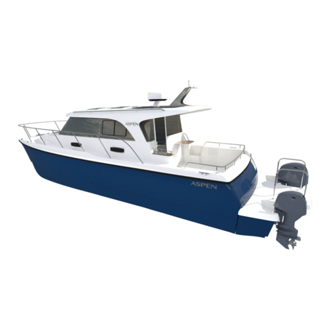
Aspen C 100 User manual

1
C 100 Owners Manual

BATTERY SWITCHES
The C100 has five main battery switches:
1) House On/Off
2) Engine On/Off
3) Emergency Parallel
4) Bow Thruster
5) Stern Thruster
Normal operation position is to leave both House and
Engine switches in the ON position. Emergency Parallel
should be in the OFF position and is rarely used.
The thruster battery switches are located below the
main battery switches and are normally ON. These
must be switched OFF when swimmers are in the
water, or for service. The thrusters are very powerful
and will suck objects in the water toward them.
Do not operate the thruster for more than 30 seconds
at a time or the motor may overheat.
The batteries have three charge sources:
1) Two ProMariner chargers (8A for Start battery and
20A for House battery). Shore power is connected and
AC breakers at dash are switched on.
2) Two 130W solar chargers (12A) while anchored –
automatic.
3) A 125A engine-driven alternator.
The boat has a Blue Sea Voltage Sensitive Relay
(black box located near switches) that disconnects
the House batteries from the Start battery when the
voltage on the Start battery drops below 12.3 volts.
Once the charging system has brought the Start
battery back to 12.3 volts, it reconnects to the house
battery bank.
2

PROMARINER CHARGERS &
FULL-TIME POWER BREAKER
Under Dinette Hatch
The 20amp House ProMariner automatic
chargers are wired to come on when the
boats shore power is connected and the A/C
breakers at the dash are in the ON position.
The chargers are four stage-smart units that
charge aggressively when the battery is low
and then ramp down as it charges. They stop
completely when the battery is fully charged
and do a small topping charge weekly. The
design greatly extends battery life and
prevents overcharging and subsequent
battery damage.
Check battery water levels monthly. Lower
water levels and/or exposed plates will
damage the batteries lead plates.
NOTE: Chargers will only charge if they see
voltage. If batteries are dead you will need to
use the Emergency Parallel Switch and charge
for maximum 4-6 minutes.
The Full-Time Power Breaker is always on. The
12V power fuse is just inside the battery switch
compartment. It is important to leave this on as
it supplies power to the boats six automatic bilge
pumps and other devices that need power to
save memory settings. It is not affected by the
battery switch position.
NOTE: If the breaker has popped or fuse is burned
out, there is no bilge pump protection from leaks.
3

1) SWITCH OFF BREAKER
SHORE POWER DISCONNECT
2) UNPLUG CORD
*NOTE: NEVER LEAVE A HOT OR LOOSE CORD ON DOCK.
IT COULD SHOCK SWIMMERS IF IT FELL IN WATER. 4

DC / AC PANELS
The AC and DC panels are both Blue Sea Systems premium panels.
DC Panel: The DC panel is fed from the House
batteries. It includes both voltage (pressure) and
amp (volume) gauges to manage your power
during the day. Reducing amps used is important
to extend battery life. While boating, turn all of the
breakers ON. The small silver toggle switch will
show Engine battery voltage (#1 left), House
battery voltage (#2 center). (The third is not
connected as there are only two battery banks.)
These breakers then feed the dash DC switch
panels (see next page) and the fuse blocks for
electronics and pumps. A DC shunt is standard for
the amp meter.
NOTE: On DC panel with bilge pump switches, the
top three switches correspond with pumps on the
starboard hull and the bottom three switches
correspond to the pumps on the port hull. First
pump is forward, second is mid-ship, and third is
aft in the port lazarette. On starboard side, the
shower pump is mid-ship.
AC Panel: This panel is fed from the 30-amp
shore power connection. Typically all of the
breakers, with the exception of the hot
water heater, are left ON to energize the
boats outlets.
If the red reverse polarity light is lit (second
bulb down), see your dock master before
continuing. It is possible some boat systems
could be damaged.
NOTE: Turn on hot water only when needed.
NOTE: This panel is fed through the whole
boat GFI, mounted just behind the deck side
shore panel connection. The whole boat GFI
does have a reset button on it.
BOAT GFI: Located on far port side
behind the dash above the Master
Stateroom bed.
5

DC PANEL LAYOUT
Pumps Panel: The pumps panel controls the bilge
pumps and shower sump pump. Most of these
are automatic, but these switches allow you to
manually turn on each of the six pumps for each
water-tight compartment. With the exception of
the fresh water switch, these switches are
normally in the off position. This panel is fed from
the pumps breaker on the main DC panel. The
automatic portion of the bilge pumps is not
affected by this panel.
NOTE: The engine room has a seventh pump
(1100GPH) which serves as an emergency pump.
It is wired to a very loud horn behind the dash.
Should you lose an engine hose and the engine
room begins to fill, this pump will automatically
start and the horn will sound.
Ship Systems Panel: This panel includes controls
for navigation lights, blower, and many other ship
systems. Like the Pumps Panel, it is fed from the
main DC panel breaker.
These panels have separate automotive blade
fuses under the plastic snap cover ranging from
5- to -20 amps. If a fuse has blown, determine
and fix the cause and replace the fuse. (Possible
causes could be debris in pump, shorted wire.)
To access fuses, carefully pop the grey cover off
with a flat-blade screwdriver or tape-wrapped
dinner knife. Pull rubber gasket over fuses and
replace fuse.
6

To Read Tank Level:
Left Gauge = Left Water Tank
Right Gauge = Right Water Tank
Center Gauge = Waste Tank
TANK GUAGES & SOLAR PANEL
CONTROLS
Solar Panel Charge Controller:
The Solar Boost 2000 is a premium charge controller
thathelpscaptureallofthesun’speakmid-day
energy. The unit is automatic and requires no
operator input. As the batteries become fully
charged, the system automatically ramps down its
charge so batteries are not overcharged. It also
automatically shuts down if it senses another
charge source (engine or battery chargers). The slide
switch is useful to see the current voltage and input
of the battery bank. If the batteries are low and the
sun is bright, the unit will put out up to 11-amps.
NOTE: If it seems not to be charging, the batteries
may be full, or the Kayaks could be blocking the sun.
1 sq ft. of shade on the solar panel will disable 2 sq
ft. of panel.
7

400 watt 12V to 120V inverter for laptops and
for charging phones.
FUSE PANELS BEHIND DASH
Blue Seas Panels: Auto Blade Fuse-Type
Each of these four fuse blocks is dedicated to a specific system and is powered by a
dedicated breaker.
1) Hot Float – 8 gang, right
2) Electronics – 6 gang, top
3) House equipment – 6 gang, middle
4) House lights – 6 gang, bottom.
The black box to the right of the helm is a Blue Seas dimmer for dash lights.
Fuses are from 3- to -20 amp, most are 5- to -10 amp.
8
Note: There is a Carbon Monoxide detector
under the edge of the bed.

Full Tabs is also used when there is excessive weight in Stern for best efficiency
LENCO TRIM TABS
The C100 is equipped with large trim tabs. The tabs are primarily used to trim the boat for
maximum efficiency and comfort while cruising. Due to their size and positioning, they can lift a
great deal while creating very limited drag.
Typically, after setting for a given throttle RPM, you will level and trim down to find the
maximum speed for that RPM. If the seas are choppy you may find that less trim is a softer and
drier ride. Use your discretion. I find that in 0 – 12”seas full tabs are most efficient and a good
ride. In 12 – 24”seas, you will need to reduce tabs to 2 / 3 or less and let the bow float through
the seas. In larger seas you may find no tab is best. Please note your best ride in heavy seas will
often be at 14 – 17Kts. If the boat is bouncing or thumping, try something different.
Zero Tabs: Used for
large seas: 14-20Kts
Half Tabs: Used for
large seas: 14-20Kts
Full Tabs: Used for 0-
1’seas:14-17Kts
*Note: Retract tabs when not in use to protect actuator shaft from marine growth.
9

Stow fenders, dock lines and kicker
motor in aft compartment.
PORT STARBOARD
GETTING READY TO GO
Fill water tanks as needed (port, starboard, cockpit fwd walls). Be sure water is good – taste
it! During long inactive periods, add a little chlorine to keep water fresh.
Note: Switch fuses are behind cover plate.
Switch on Engine blower. Switch on refrigerator, lower left DC panel.
10

GETTING STARTED: THRUSTERS,
RADIO & WIPERS
Thrusters: These side power units are very handy while
docking.
Caution: Be certain no one is in the water near the boat
when the thrusters are on. The thrusters work like a
vacuum, sucking from a large area.
To use, ensure battery switches are on, then press both
ON buttons simultaneously. A green light will illuminate
signaling the joy sticks are ready. Press bow stick left and
boat will got left.
Use in 20 – 30 second bursts and never for more than
three minutes of continuous use to make sure motor
keeps cool. Unit shuts off automatically after three
minutes of inactivity.
A wireless remote is available for solo docking.
NOTE: When using thrusters make sure inverters are off.
Otherwise, the low voltage alarm will ring on the inverter.
Thrusters use a lot of voltage and may even cause low
voltage on the chart plotter.
ICOM VHF Radio
Turn on by rotating top right knob. Most
conversations with other boaters will be on low
power. Channel 16 is used only for hailing.
Switch to Channels 72 or 68 for other
communication. Weather information is
available by pushing the WX button. Use the
lower knob to squelch background static.
Wiper Motor
The controls are on the left side of the dash. The
wipers have two speeds. Push the control to
wash. Wash tank is located in the back corner of
the storage bin, behind the refrigerator, under
the helm seat. You will have to remove safety
gear to gain access. Rain-X works great on front
and side windows to aid in visibility. 11

Starting Engine: Once batteries and blower are
on you can start. Hold Key Fob flat with square
edge toward key box and pass down over box.
A green light will come on solid, then push
start button after fuel pressure pump has
stopped humming. Important: you must warm
theengineupslowlyatRPM’sunder2000over
a 10-15 minute period. DO NOT go above 2000
RPM until motor has reached 176 degrees. 80%
of engine wear is while motor is cold.
Safety Gear Storage/Owner Manuals
GETTING STARTED: ENGINE &
SAFETY GEAR
Engine Computer: The engine computer is
very useful as it allows you to view engine
data. Toggling the propeller button allows
you to scan various details. It is fine to push
the boat and horizon buttons for additional
information. Oil pressure while running will
be about 90 PSI and water temperature will
be about 176 – 180 degrees.
NOTE: If you hear a horn or beeping sound
while underway you must stop and
determine the cause. Engine manuals can
be found under the helm seat in a black
brief case.
12

1) Press Charts. 2) Press Navigation Charts.
GARMIN CHART PLOTTER
To start the chart plotter, locate the power button at the top right of the unit. Press and
hold the power button for three seconds. The unit will start in approximately ten
seconds.
The screen will display chart and data fields. To zoom in, press the + key; to zoom out,
press the – key. To change the page to sounder, press the home button and toggle to the
desired page.
NOTE: To dim the unit at night, tap the power button and use the active button to adjust
light level. You must turn the light level back up when done or the screen will be black the
next day, making it difficult to see the buttons.
13
GARMIN HELP LINE #1-800-800-1020

WALLACE 30D HEATER
The Wallace furnace control is located to
the left of the helm. To turn on, push
toggle switch to right and rotate fan-heat
control knob to desired level. The
controller has no thermostat due to size of
space heated.
The unit is located under the sink. Note:
When first warming up, it may howl for a
few moments; adjust speed to stop.
During its first operation, it may time out
as the fuel pump did not prime, -restart
unit.
The vents are located in the salon,
at the dash and in the master
stateroom. Do not block the flow as
this will shut the unit down from
overheating. There is a boost fan for
defrosters, switch it on at DC panel
to left of helm. We have found at
times on the lowest flow setting it
may shut off after 4-6 hrs. To reset,
trip the constant hot power breaker
in the engine room and then reset
breaker on.
Note: If a vent is not flowing, pop grill
off, twist valve inside open. 14

Quick-start Operations Checklist:
1) Ensure seawater-intake ball valve is open.
2) Make sure the control is powered off.
3) Turn on the air conditioner circuit breaker. If
theseawaterpumphasit’sowncircuitbreaker,
turn that on also.
4) Turn the control ON.
5) Press the Fan button. Verify that the fan is
running and that there is steady airflow out of
the supply-air grille.
6) Select a temperature set point lower than
the current cabin temperature. This starts the
compressor and seawater pump.
7) Check for a steady solid stream of water
from the overboard discharge.
8) Verify that there is a steady airflow out of
the supply-air grille.
For more specific operation instructions, see
your AC Unit owners manual for further detail.
The unit is located under the sink.
A/C UNIT
The vents are located in the salon, at the
dash and in the master stateroom. Do not
block the flow as this will overheat the
unit and cause it to shut down. There is a
boost fan for defrosters. It can be
switched on at the DC panel to the left of
the helm. We have found that at times it
may shut off after 4 – 6 hours on the
lowest flow setting. To reset, trip the
constant hot power breaker in the engine
room and then turn breaker back on.
Note: If a vent is not flowing, remove the
grill and twist the inside valve open. 15

The propane sniffer control unit is just fwd
of the sink. This units power may be
switched with the black switch just below
it. The sniffer is very sensitive and false
alarms can be disconcerting. When its off,
the solenoid valve in the tank is closed.
When stove is not in use, tap the control
button and turn the gas off . It will take
about 30 seconds before the sensor can
be turned to ON position.
Green light when Power is ON, but unit is OFF. Gas is ON when the green Light is ON.
PROPANE SNIFFER CONTROL
16

The windlass breaker is located in the
master staterooms hanging locker,
just forward of the bow thrusters
service hatch. Note: The anchor line
end must be secured to the bitter end
cleat in the anchor locker. Be sure to
secure the anchor with a bungee or
line while underway.
LEWMAR WINDLASS
The Lewmar windlass is mounted on the front deck. For ease of use, it has power controls
locatedatboththehelmandfrontdeck.Theunituses¼”chain,typically40’,and250’of½”line,
typically triple-braid,that’sbeenwoventothechain.Thecapstancanhandleboththechainand
line, transitioning automatically as the line moves through. When the line is new, it is a good
idea to remove the anchor at its swivel and run the line up and down two-to-three times to clear
any kinks in the line.
The windlass has a friction clutch built in to
the capstan. Its tension is adjusted by turning
the SS knob and tightening clockwise for more
friction, counterclockwise for less friction.
This is a delicate procedure, as too little
tension causes the clutch to slip when lifting
under-load. Too much tension while the
anchor is lifted can cause damage. When the
anchor rode has been purchased from Aspen,
itincludesdepthmarkersevery30’toaidin
anchoring. 17

ANCHOR WITH SNUBBER BUNGEE LINE AFTER STACKING - DETANGLE
Use wrench to tighten/loosen clutch, capstan.
Note: The wrench is key to adjusting how
much force the windlass pulls in with. Too
tight and you will damage the roller assembly.
*Usedon28’andearly32’Aspens*
ANCHOR DETAILS
ANCHOR DEPTH MARKERS WINDLASS WRENCH
18

The Tilt Helm lever is located under the
steering wheel.
Running attitude, 16 Kts, tabs down. Master Curtains snap in. Each is Labeled
Port/Starboard with arrow showing
forward. Fold and store in headboard
bookshelf.
TILT HELM & CURTAINS
The hydraulic fluid (Teliflex) fills at the top
under rubber cover.
19

First, set water to preferred temperature. The sink wand lifts to hanger near the
door. The curtain from shelf behind door is snapped into the ceiling buttons. Dry
door and shower floor when done. Door can be left open or closed while
showering. The automatic sump pump under the head evacuates the water.
Note: Toconservewater,“boat”showersarerecommended.Getwet,turnoffwater,
soap up, rinse off!
Before leaving the boat for an extended period of time, sponge out the sump under
the toilet to eliminate odors.
Sprayer has three positions:
OFF ON ON FULL TIME
SHOWER CURTAIN & SPRAYER
20
Table of contents
Other Aspen Boat manuals