WARNINGS
Electricity is a source of danger.
Before using this product, make sure that the use of the same
complies with current legal provisions to safeguard your own
health and safety as well as that of others. Therefore, it is ne-
cessary to use the product in accordance with current regula-
ons, standards and provisions to safeguard your own health
and safety, by following the instrucons, fully complying with
the condions prescribed in this manual.
Untrained, unaware individuals and minors
It is strictly forbidden to allow children, individuals who have
not been appropriately informed and non self-sucient people
to use the product without the supervision of an adult who is
aware of how to properly use such equipment.
It is forbidden to use the product for any other purpose other
than that specied in the instrucons, or that may go beyond
its intended use that could prove to be a source of danger.
Foreseeable or unforeseeable misuse
Any use of this baery charger other than that specied in the
instrucons, or which goes beyond the designated use, is con-
sidered as non-compliant. Therefore, it is deemed as incom-
pable, improper, unforeseeable misuse and for such reasons,
this conduct brings about a high level of danger. Consequently,
with immediate eect, AlcaPower shall not be held responsi-
ble in any way whatsoever for damage caused by means of the
abovemenoned conduct.
Exempon from liability
Under no circumstances whatsoever shall AlcaPower Distribu-
zione Srl be held responsible in the following cases:
• If the product is not used properly.
• If the safety standards and regulaons are not complied
with.
• If improper and reasonably foreseen uses of the product
is not considered.
• If the assembly procedure and/or electrical connecon
are not carried out properly.
• If the correct operaon of the product is not regularly
inspected.
• If repairs and/or modicaons are made to the product
that alter its integrity.
Serious damage or injuries!
In the event of incorrect or inappropriate electrical con-
necons!
Electrical connecons must be carried out by paying parcular
aenon, in accordance with standards and regulaons to sa-
feguard your own health and safety.
Serious accidents in case of the selecon of fun-
cons and operaons!
• Despite the safety protecons present on the product,
check that operaons caused by the incorrect selecon of
funcons are not carried out.
• Select the funcons so that the safety protecons can act
in accordance with safety standards.
• Select the funcons as described in the instrucons.
• Any connecon to other equipment must be monitored to
guarantee the utmost level of safety.
An error may cause high risk situaons!
Before, during and aer use: cables, plugs and connectors must
be carefully checked to avoid a short circuit and to make sure
that they are intact and have no bare wires or parts that are
even parally damaged.
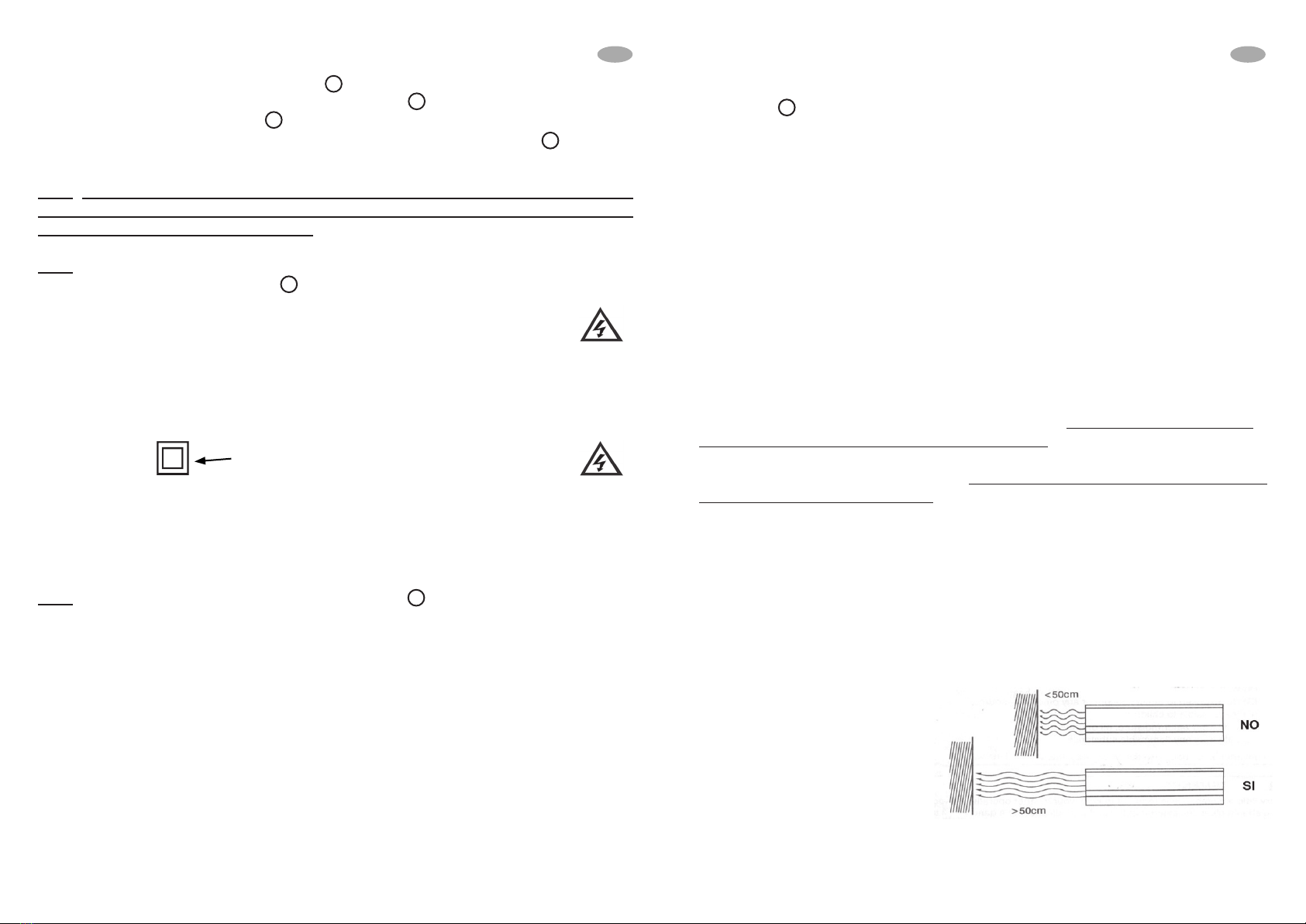
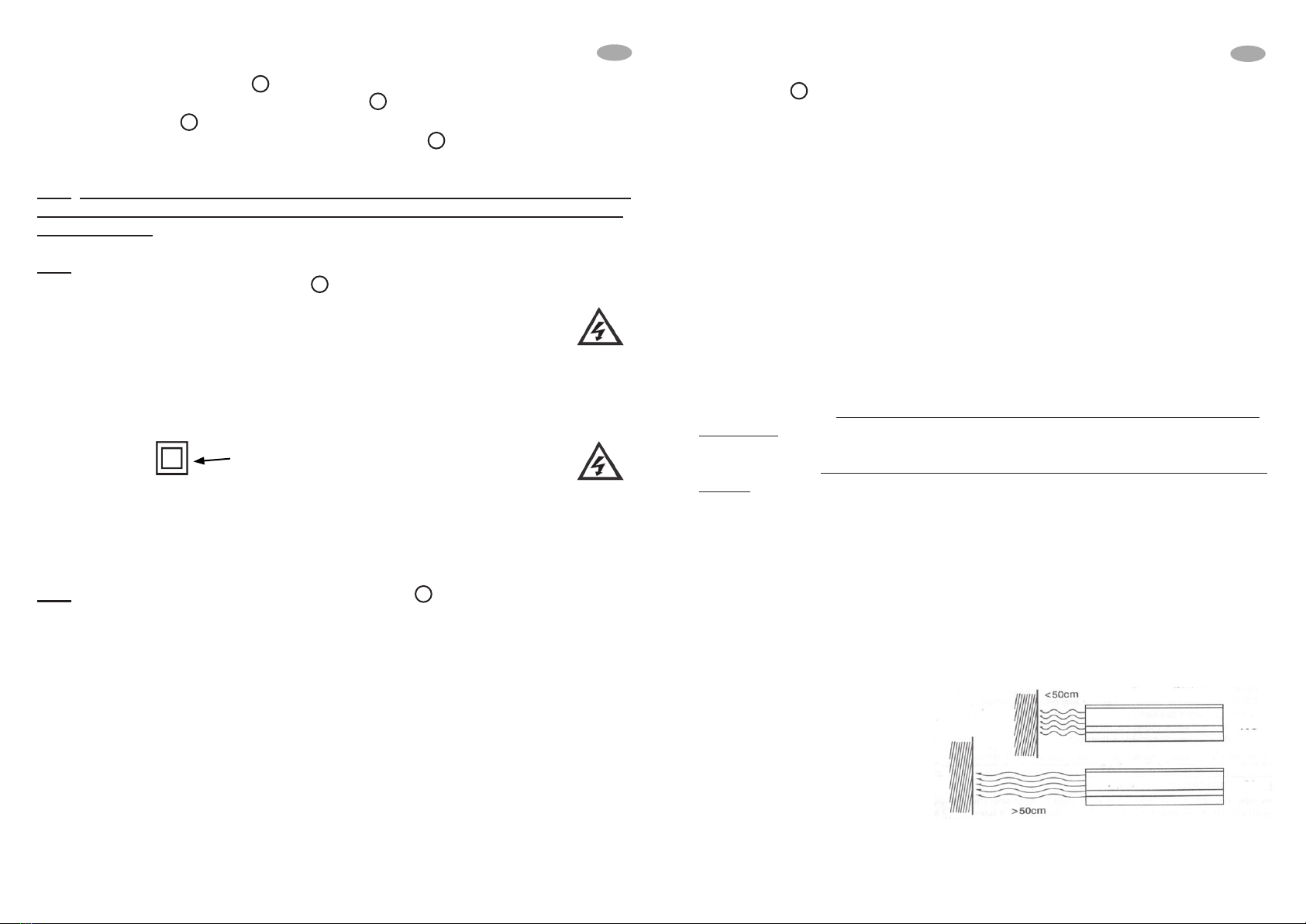
Pay aenon to the environment in which you are
working!
Hazardous situaons may be caused by the people, animals or
materials present in the surrounding environment in which you
are using the product. Humidity, gas, vapours, fumes, liquids,
noise, vibraons, high temperatures, possible falling of mate-
rials, and explosive atmospheres.
Inadvertent product start-up and/or interrupon!
Hazardous situaons may arise following inadvertent and sud-
den start-ups or interrupons of the operaonal funcons of
the product. Carry out inspecons and check prior to starng
up or interrupng the operaonal funcons of the product.
Abnormal operaonal funcons!
ln the event of abnormal operaonal funcons of the product,
it is necessary to promptly interrupt the operaon of the pro-
duct. See the instrucons in the product-specic user manual.
Warranty: this product is covered by a warranty under the
terms of the current applicable law. In case of need, contact
the sales outlet where you bought the product.
DECLARATION OF CONFORMITY (Extract)
AlcaPower Distribuzione Srl does hereby declare that the pro-
duct complies with essenal requirements set forth by current
legislaon.
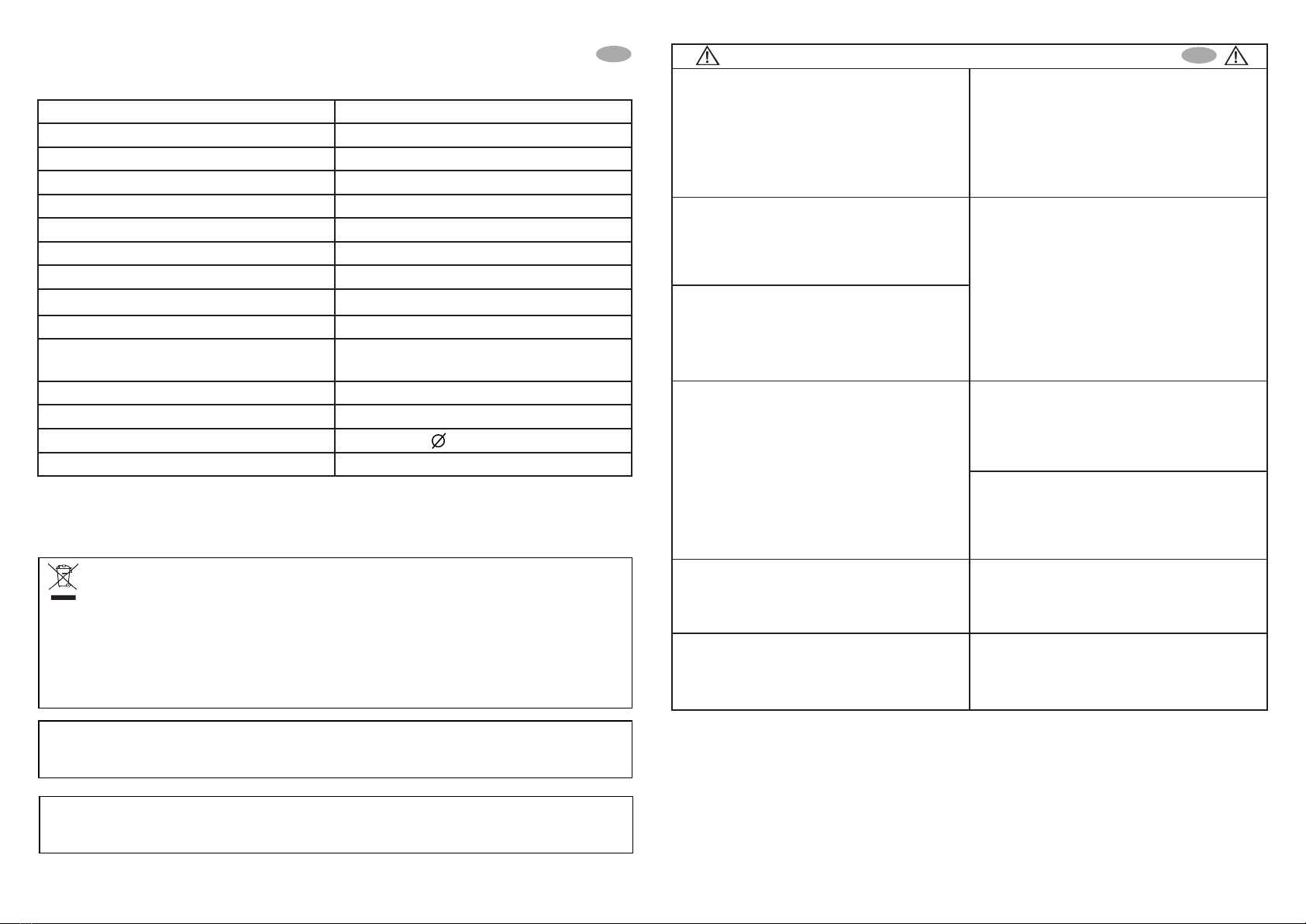
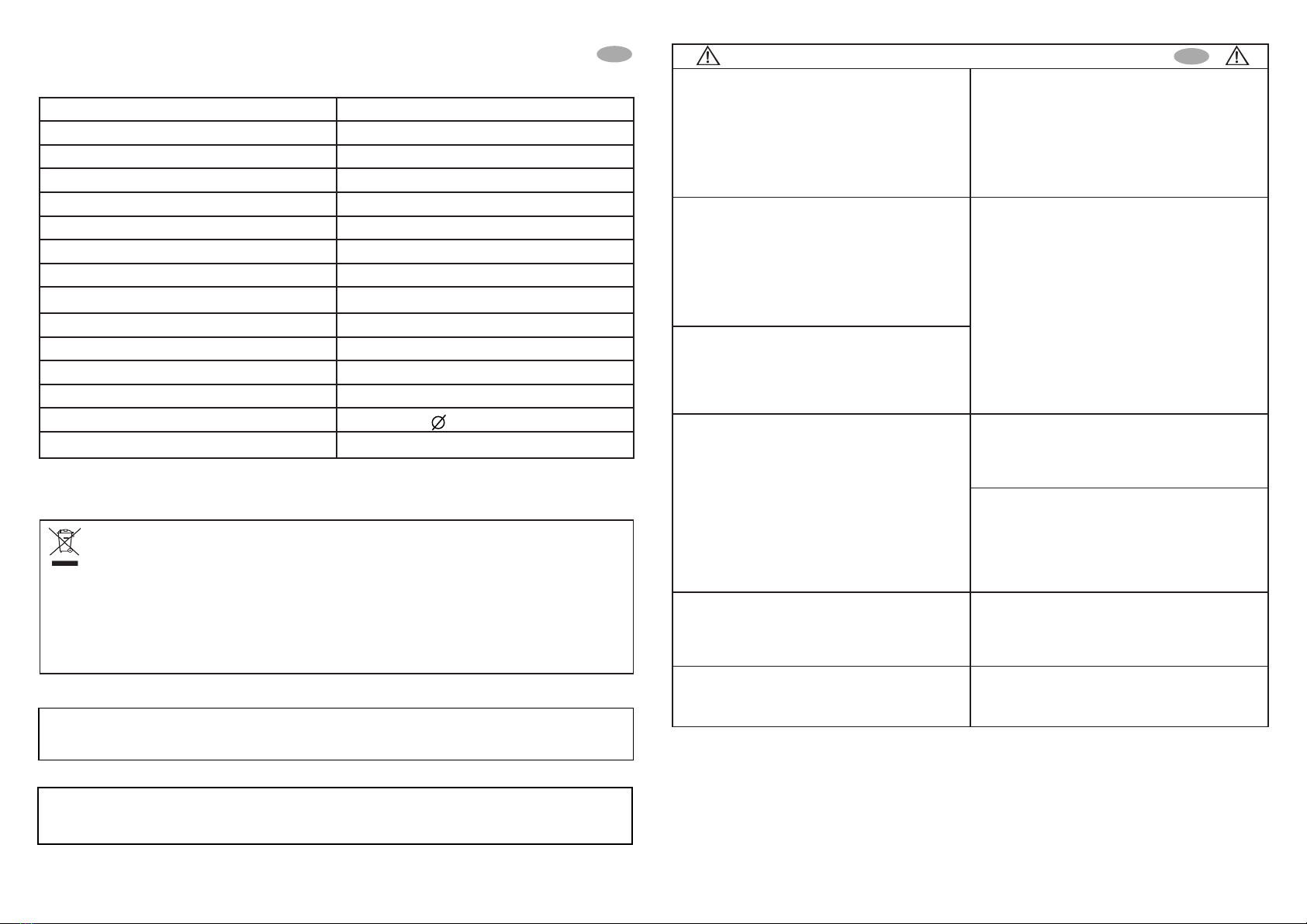
Model AP12-150LT
Input voltage 11-15V DC
Output voltage 230V AC ± 10%, 50Hz ± 3Hz
USB output 5V DC, 500mA max
Continuous power 150W
Peak power 300W
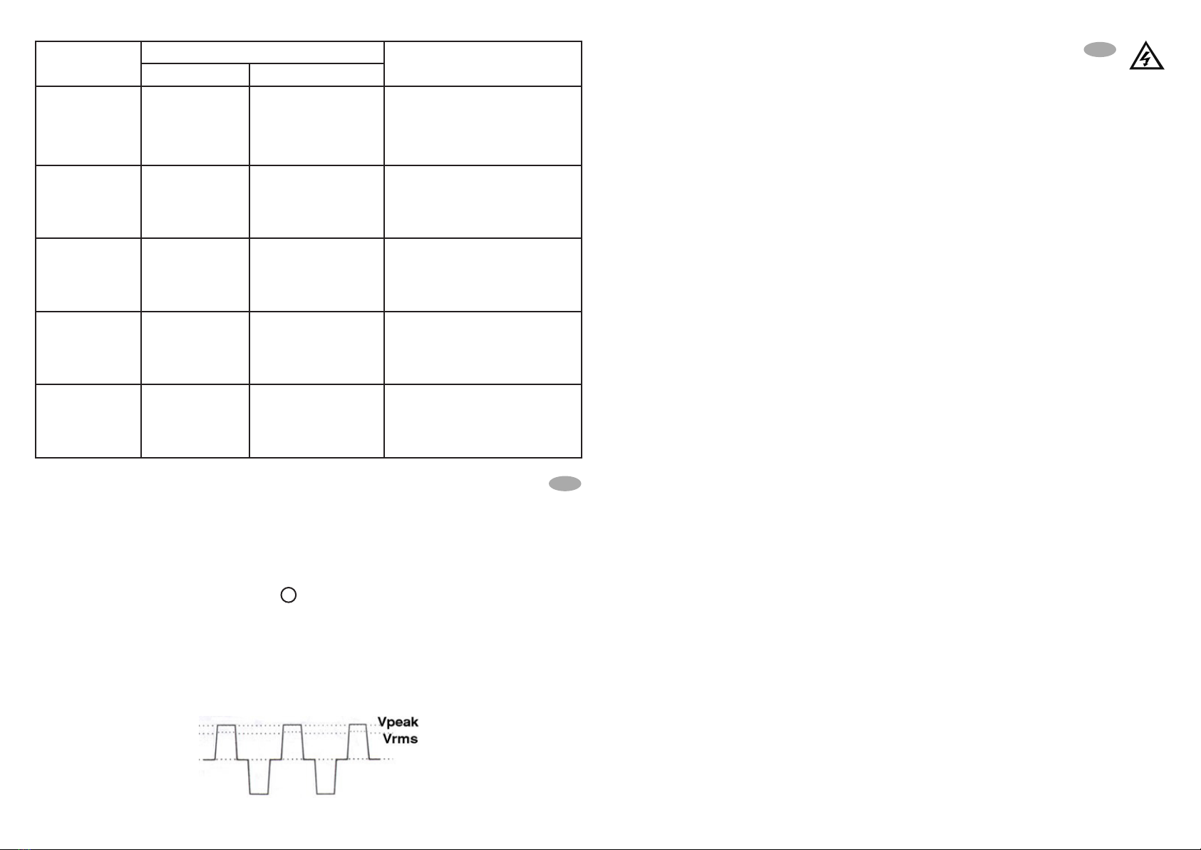
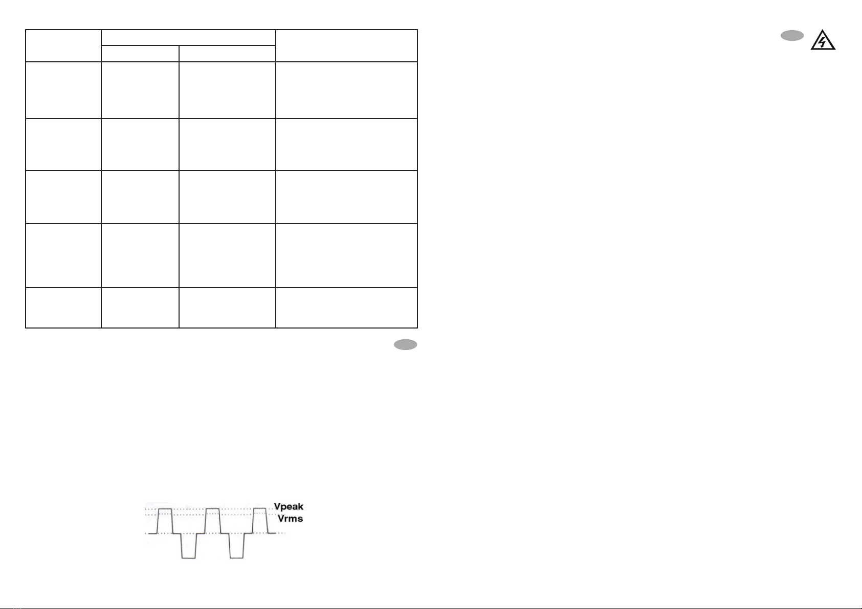
Output waveform Modied sine wave
Eciency >80%
No load current < 0.45A
Input low voltage shutdown 10.5V DC ±0.3V
Input overvoltage shutdown 15V ~ 16V DC
Input fuse 25A
Optimal working temperature From 5°C to 35°C
Dimensions 72x150mm
Weight About 430gr
TECHNICAL CHARACTERISTICS
EN EN
DISPOSAL. The crossed dustbin symbol reported on the product indicates that, at the end of its
useful life, the product must be collected separately from other waste. Therefore, the end-user must deliver
the product to the collection centers for electric and electronic waste (WEEE). Alternatively, the product can
be returned to the retailer shop when buying a new product of the same type, in a ratio of one to one, or
one to zero for products having external dimension no more than 25cm. A separate collection guarantees
the recovery and reuse of the materials used in manufactoring the product, contributes to the respect of the
environment and the protection of health by preventing pollution and reducing the need for raw materials.
Note: all pictures shown in this manual are for illustration purpose only, are not contractual and may dier
from the actual product.
AlcaPower - AP12-150LT - User Manual V1 R3 [12/03/2018] © All right reserved.
6 7