11
(f)Installation of Surge Suppressor
For inductive loads (magnetic contactors, magnetic relays, magnetic valves, solenoids, magnetic
brakes, etc.) connected near the inverter, use a surge suppressor simultaneously.
(g)Prohibition of Installation of Phase Advancing Capacitor
If a phase advancing capacitor or surge suppressor is connected in order to improve the power factor,
it may become overheated and damaged by inverter high harmonic components. Also, the inverter
may malfunction because of overcurrent.
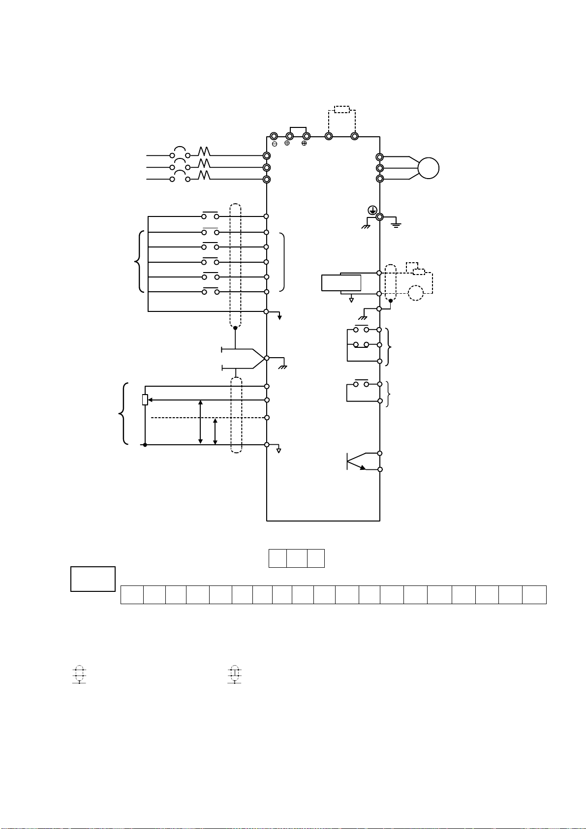
(2)Wiring Precautions for Main Circuit Output
(a)Connection of Terminal Block and Load
Connect output terminals U, V and W to motor lead wires U, V and W. Verify that the motor rotates
in the forward direction (CCW:counterclockwise when viewed from the motor load side) with the
forward run command. If the motor rotation is incorrect, exchange any two of output terminals U,V
or W.
(b)Strict Prohibition of Connection of Input Power Supply to Output Terminals
Never connect input power supply to output terminals U, V and W.
(c)Strict Prohibition of Short Circuiting or Grounding of Output Circuit
Never touch the output circuit directly or put the output line in contact with the inverter case.
Otherwise, it may cause an electrical shock or grounding. In addition, never short circuit the output
line.
(d)Prohibition of Connection of Phase Advancing Capacitor or LC/RC Noise Fitter
Never connect a phase advancing capacitor or LC/RC noise, filter to the output circuit.
(e) Avoidance of Installation of Magnetic Starter
Do not connect a magnetic starter or magnetic contactor to the output, circuit.
If the load is connected while the inverter is running, the inverter overcurrent
protective circuit operates because of inrush current.
(f) Installation of Thermal Overload Relay
An electronic overload protective function is incorporated into the inverter.
However, connect a thermal overload relay when driving several motors with one inverter or when
using a multi-pole motor. When using a thermal overload relay, set inverter constant H033 to 0.
Additionally, for thermal overload relay, at 50Hz set the same rated current value as that described
on the motor nameplate, or at 60Hz 1.1 times larger than the rated current value described on the
motor nameplate.