Alcolock V3 B-2 Series User manual

Service Guide
V3
SERIES B-2

Alcohol Countermeasure Systems Corp
60 International Boulevard
Toronto, Ontario M9W 6J2
Canada
T +1 416 619 3500
F +1 416 619 3501
acs-corp.com
© 2012 Alcohol Countermeasure Systems
The information disclosed in this document is the valuable property of Alcohol Countermeasure Systems Corp.
and all copyright and other proprietary rights to this document are reserved. No reproduction of this document is
permitted without the prior written consent of Alcohol Countermeasure Systems Corp.
ALCOLOCK, ALCOHOL COUNTERMEASURE SYSTEMS and the Molly are trademarks of Alcohol
Countermeasure Systems (International) Inc., and are used under license.

GENERAL INSPECTION
• Visually inspect the handset. No damaged ordisconnected parts should be present.
• Check that none of the labels on the handset are loose.
• Check the cables for any cuts or nicks, also check thatthe cable connectors are not exposed.
• Check that the mouthpiece insertion area of the handsetis free of debris, dirt or contaminants.
MAINTENANCE PROCEDURES
• Maintenance of the unit is insured through calibration. Please refer to the calibration
procedures section of this guide for step by step instructions to calibrate the unit.
• V3’saremadeforelduse,makingthemsusceptibletodirtanddebris.Thehandsetshouldbe
cleaned with adamp cloth and mild soap. Do not use abrasive cleaners or solvents on the unit.
GENERAL FUNCTIONAL TEST
The following are some actions to test the functionality of the interlock system.
To test that all inputs to the V3 are off, and that both pushbuttons are working: if the handset is
awake, hold both pushbuttons for 3 seconds. The handset should go to the lower power state, the
display and all the LEDs should turn off.
To test the display, backlights and left pushbutton: Wake the handset
up by pressing the left pushbutton. The display should show, “Alcolock
Disabled, OK to start engine”.
To test the ignition input: turn the ignition to the ON position, the display
should show “Start motor”. The status LED should be green, and a
series of tones should be heard.
To test the engine run input, and the green status LED: start the motor
of the vehicle, the display should show “Disabled” and the status LED
should be green
To test the right pushbutton: turn off the ignition and hold the right
pushbutton for 3 seconds. The display should show, “Alcolock
Disabled, OK to start engine.”
Alcolock
Disabled
OK to start engine
Activate(hold)
Start motor
Cancel(hold)
Disabled
Alcolock
Disabled
OK to start engine
Activate(hold)

SERVICE PROCEDURES
In the event of an error code occurring, follow the series of actions in the following table to isolate
the error. Start with action 1, if the action is not the source of error, then go through the list and
carry out each subsequent action till you get to a conclusion. If a part of the interlock needs to be
changed, ensure that the correct replacement ECU is used depending on the voltage of the car
battery.
PART NUMBERS OF REPLACEMENT PARTS:
V3 Handset 79-009000
V3 Series B2 24V ECU 79-008847
V3 Series B2 12V ECU 79-008811
MESSAGE CAUSE ACTIONS TO TAKE
ADR incompatible Handset or ECU hardware is
not ADR compatible.
1. Verify handset P/N.
2. Verify ECU P/N.
Clock Error No date/time information
has been received from the
tachograph over the CAN BUS.
1. Check if tachograph is
functioning properly.
2. Check wiring from
tachograph to ECU.
3. Replace ECU.
Communication error Handset has lost
communication with ECU.
1. Check voltage of vehicle
during ignition cranking.
Voltage should stay above
9V or 16V depending on
ECU.
2. Replace spiral cable.
3. Replace ECU.
4. Replace Handset.
ECU voltage incorrect ECU is connected to wrong
voltage source.
1. Verify ECU P/N.
Error code 40 Sampling pump piston within
the fuel cell is stuck in the rest
position.
1. Replace handset.
Error code 45 Sampling pump piston within
the fuel cell is stuck in the
middle of the cylinder.
1. Replace handset.
Error code 50 Sampling pump piston within
the fuel cell is stuck in the active
position.
1. Replace handset.
Handset voltage too high Voltage reaching handset is too
high.
1. Start motor and verify that
voltage supplied to ECU is
not above 20V or 32V.
2. Replace ECU.

Handset voltage too low Voltage is too low for normal
operation.
1. Check voltage of vehicle
during ignition cranking.
2. Replace ECU.
3. Replace handset.
RF error High levels of RF interference
detected
1. Verify if client was using a
mobile phone or in an area of
high RF signal interference
during use. If yes no action is
required.
2. Replace handset.
Software incompatible Firmware in handset and ECU
is not compatible.
1. Verify handset P/N.
2. Verify ECU P/N.
Technical error Technical problem in the
ECU. One or more fuse(s) is
potentially blown.
1. Conrmthatvehiclevoltage
reachingECUissufcient.
2. Replace ECU.
CALIBRATION PROCEDURES
It is recommended calibration be done indoors in a service facility, using an ACS
download station.
The calibration procedures are intended for use by trained technicians only.
EQUIPMENT NEEDED
• 130PPM (0.05 %BAC) Alcohol gas standard ACS #95-000425
• Regulatorvalveassembly(6L/min.owrate)ACS#94-000225
• V3 Download station ACS #79-006111
COMPRESSED GAS SAFETY
Calibration should be performed indoors in a service facility, where the gas
standard cylinder can be properly stored.
Transportation and storage of compressed gases in vehicles is dangerous and should be avoided.
Other precautions:
• Never remove or alter canister labels.
• Remove the valve and install the protective cap on cylinders when not in use.
• Store cylinders in a cool, well ventilated area, away from sources of heat.

CYLINDER SETUP
1. Examine the canister and valve for any damage, and check the expiration date on the label.
Observe all cautions and safety warnings found on the canister.
2. Remove the protective cap and screw the regulator valve to the canister. Attach the rigid
delivery tube. Never modify the delivery tube in any way.
CAUTION! Damaged or broken valves can turn a canister into an unguided missile.
Attach the valve in a safe location.
CALIBRATING A HANDSET
1. Power the handset on by holding down either the right or left button.
2. Access the Menu by pressing and holding the left button. Scroll through the menu and select
System Maintenance. The four digit code which is provided with the V3 accesses this
menu.
3. Enter the code and move the cursor to OK?whennished.PushtherightbuttontoSelect.
This enters the Service menu.
4. Scroll through the Service menu and press select Calibration.
5. The current handset Date/Time is displayed. To proceed select OK with the right button. This
enters the Select Type menu.
NOTE! If a tachograph is installed the date/time cannot be changed.
6. The Select type menu contains the calibration options. Scroll to Dry Gas and push the right
button to Select. This enters the Select value menu.
7. The Select value menu contains the gas standard concentration options. Verify that 130PPM
is on the canister label, and use the left button to scroll to 130PPM. Push the right button to
Select. This enters the Altitude menu.
8. The Altitude menu contains the altitude correction factor. Verify the altitude value using the
altitude reference guide, which is on the last page of this guide. The left button increases in
increments of 200 meters. Press the right button to Accept.
9. A Wait message is displayed followed by a 2:00 minute warm-up. The handset is ready for
calibration when the Turn on gas message is displayed.
10.Insert the delivery tube from the regulator valve into the mouthpiece port. Keep hold of the
handset as the delivery tube is rigid.
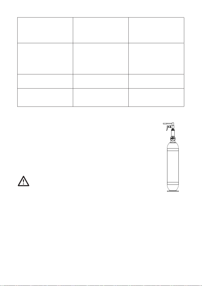
11. Press the valve down to release the gas while keeping
holdofthehandset(seegure).Thehandsetanalyzes
the gas standard and displays a Blowing… message
followed by Analyzing message.
Continue holding the valve down until the handset clicks
and then beeps, indicating that the test is complete.
12.Thehandsetanalyzesthetest,whichis
followed by a Wait message and 0:45 second
countdown. The handset is ready for the second sample
when the Turn on Gas message is displayed.

Depending on the sensor calibration drift, up to 4 samples may be required.
• If only 2 tests are required, a Verication OK message is displayed when thecalibration
is complete.
• If 3 or 4 tests are required, a Calibration OK message is displayed when calibration is
complete.
13.Press the right button to Finish (there is also the option to retry by pressing the left button).
Calibration is complete.
The V3 handset returns to ready state and Blow for 5 seconds is displayed.
NOTE! If the calibration fails on numerous attempts, the sensor may need
replacement. Contact ACS for return instructions.
TROUBLESHOOTING
Intheeventofacalibrationfailure,rstcheckthesecommoncausesoferrors:
• Plastic tubing has been overused, or has condensation present.
• The alcohol gas standard value is not 130PPM, or the value has been incorrectly entered in the
Select Value menu.
• The alcohol gas standard is expired.
• A connection to or from the gas valve is not secured properly (check all connections).
• The value entered in Altitude menu is incorrect.
ALTITUDE REFERENCE GUIDE
The altitude adjustment is in increments of 200 meters. Choose the closest city elevation and
round the altitude up or down to the closest value accordingly.
EXAPMLE
CITY ALTITUDE (M) SETTING
Amsterdam 0 0
Berlin 34 0
Brussels 48 0
Geneva 373 400
Madrid 654 600
Moscow 189 200
Ottawa 79 0
Paris 34 0
Rome 14 0
Washington 7 0

SG-ENG-60-000130-D
© 2012
This manual suits for next models
3
Table of contents
Other Alcolock Test Equipment manuals