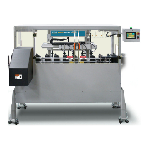
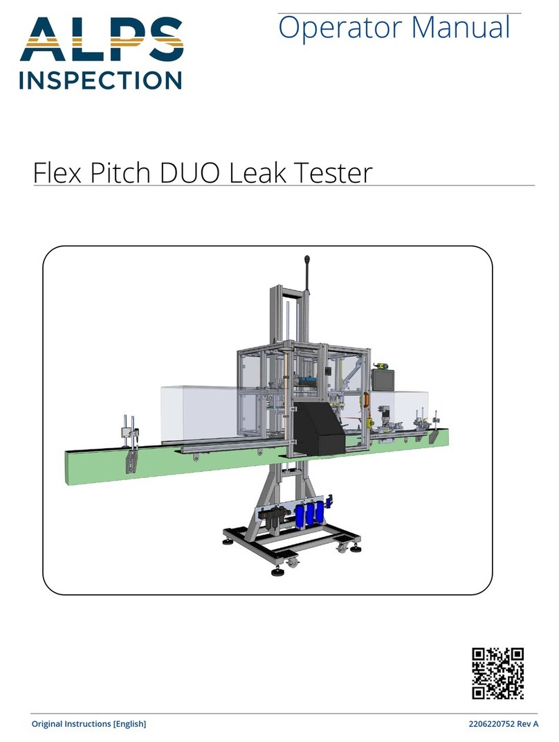
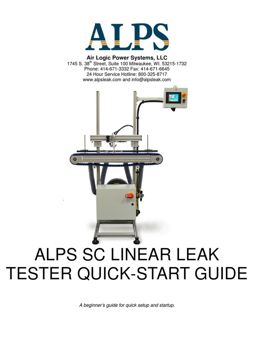
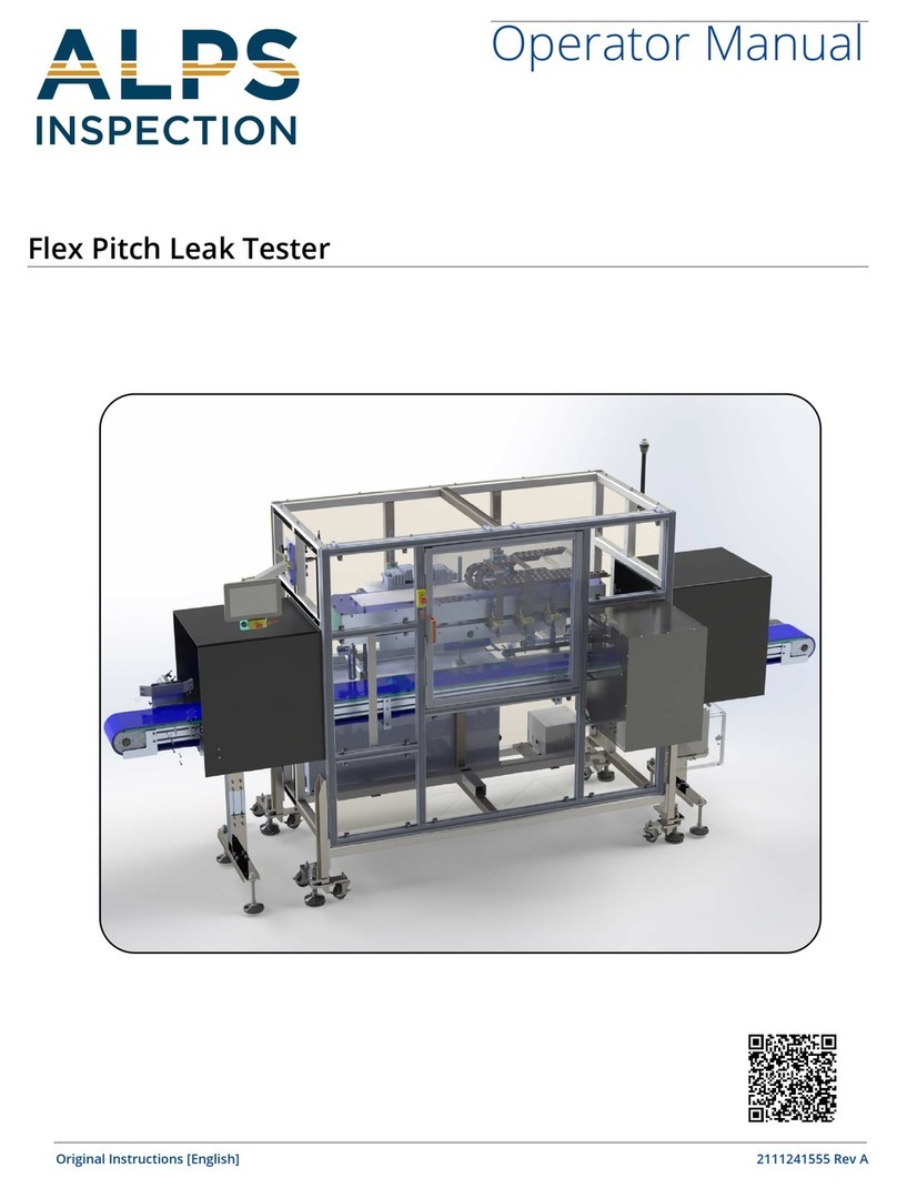
Alps Electric FlexPitch User manual

FLEX PITCH ADVANCED OPERATOR MANUAL i TM 2017-005 REV03 © 06/31/2017
ALPS
Air Logic Power Systems, LLC
2440 W Corporate Preserve Drive Unit 600
Oak Creek, WI 53154 - USA
Phone: 414-574-4151 Fax: 414-574-4152
24 Hour Service Hotline: 800-325-8717
FLEXPITCH LEAK TESTER
ADVANCED OPERATOR MANUAL

AIR LOGIC POWER SYSTEMS (ALPS) NOTICES
FLEXPITCH ADVANCED OPERATOR MANUAL ii TM 2017-005 REV05 © 08/01/2017
Notices:
Documentation
Air Logic Power Systems LLC (ALPS), reserves the right to make changes or improvements to the
FlexPitch Multi-Moving Head Leak Tester at any time. These changes may not be immediately
reflected in the manual accompanying your system. If you notice any inaccuracies or oversights in
this manual, please contact the ALPS Service Department.
This manual is protected by U.S. federal copyright laws © 2017 Air Logic Power Systems LLC.
However, limited permission is hereby granted to photocopy portions of this manual for training of
company personnel only. No part of this manual may be duplicated or transcribed in any form, for
any other purpose, except as stated above, without expressed written permission from Air Logic
Power Systems LLC.
Software
Installation of any new or modification of existing software into the FlexPitch machine not approved
by Air Logic Power Systems LLC may adversely affect the operation or performance of the machine
and possibly void the warranty and or service agreements. Please consult Air Logic Power Systems
Service Department prior to installing or modifying existing software on this machine.
System Modifications
Mechanical or electrical modifications not approved by Air Logic Power Systems LLC to the
FlexPitch system may also void the warranty and/or service agreements. Please contact the Air
Logic Power Systems Sales or Service Department for approval or assistance with any machine
modifications.
Trademark and Patent Acknowledgments
All products or product names mentioned in the manual are trademarks of their respective
companies. The product name: FlexPitch ™.
Contact Information
Service Department 24 Hour Hotline (US): 1-800-325-8717 (International): 1-414-574-
4151
Service Manager, Ext. 22180
Sales & Customer Service Support, Ext.
Sales Manager, Ext. 184
Air Logic Power Systems LLC, Headquarters
2440 W Corporate Preserve Drive Unit 600 Oak Creek, WI 53154 - USA
Phone: 414-574-4151 Fax: 414-574-4152
Copyright © 2017 by Air Logic Power Systems LLC

AIR LOGIC POWER SYSTEMS (ALPS) CONTENTS
FLEXPITCH ADVANCED OPERATOR MANUAL ii TM 2017-005 REV05 © 08/01/2017
Table of Contents
General Information 4
Machine Designation and Serial Number location..................................................................5
Safety 6
Safety: Warning Labels and Descriptions ..............................................................................6
Safety: Warning Messages ....................................................................................................9
Jokab Door Sensors: Positions............................................................................................10
Safety-Operational Status/Conditional Status......................................................................11
Glossary of Common Terms 12
Introduction to Components 13
Operational Components.....................................................................................................13
Working Components...........................................................................................................14
Theory of Operations15
Leak Test Operations...........................................................................................................15
Photo Eye Function and Position 16
Photo Eyes Introduction and Positions.................................................................................16
Advanced Operator HMI Use 17
Password Protection............................................................................................................17
ALPS Password Definitions Overview..................................................................................17
How to Log In and Out.........................................................................................................18
How to Enter Passwords......................................................................................................19
How to Edit HMI Settings.....................................................................................................20
The Setting Menus 21
Test Pressures & Reject Limits Overview............................................................................21
Test Pressures & Reject Limits Overview .........................................................................22
Test Pressures & Reject Limits Helpful Hints.......................................................................23
Bottle Size and Stroke Overview..........................................................................................24
How to Use Bottle Size and Stroke......................................................................................25
Probe Take Off Overview.....................................................................................................26
How to Use Probe Take Off .................................................................................................26
Conveyor Speed Overview and Use....................................................................................27
Reject Timing Overview.......................................................................................................28
How to Use Reject Timing....................................................................................................29
Optional Functions Overview & Use.....................................................................................30
Recipes Overview................................................................................................................32
How to Use Recipes.............................................................................................................33

AIR LOGIC POWER SYSTEMS (ALPS) CONTENTS
FLEXPITCH ADVANCED OPERATOR MANUAL iii TM 2017-005 REV05 © 08/01/2017
Test Results Menu 40
Counters Overview...............................................................................................................40
All Results, Individual Results, Timer Details and Recent Rejects Overview.......................41
How to Use All Results.........................................................................................................42
How to Use Individual Results..............................................................................................43
Individual Results Description Table....................................................................................43
How to Use Timer Details ....................................................................................................44
How to Use Recent Reject...................................................................................................45
Alarm Log & Counters Overview..........................................................................................46
How to Use Alarm Counters.................................................................................................47
How to Use Alarm Log.........................................................................................................48
Maintenance Menu 49
Manual Test Overview .........................................................................................................50
.............................................................................................................................................50
How to Use Manual Self Test...............................................................................................54
Inputs and Outputs Overview...............................................................................................55
How to Use Inputs and Outputs ...........................................................................................56
Station Diagnostic overview.................................................................................................59
How to use Station Diagnostic .............................................................................................60
Analog Calibration Overview and Use..................................................................................61
About Overview and Use .....................................................................................................61
Supervisor Menu Introduction 62
System Options Overview....................................................................................................62
How to Use System Options ................................................................................................63
Auxiliary Test Overview........................................................................................................63
How to use Auxiliary Test.....................................................................................................64
Reject Alarms Overview.......................................................................................................65
How to Use Reject Alarm.....................................................................................................66
System Bypass Overview and Use......................................................................................67
Select Inputs Outputs Overview and Use.............................................................................68
Auto Self-Test Overview ......................................................................................................69
How to Use Auto Self-Test...................................................................................................70
Bottle Change Over and Setup 71
Change Over Steps Guide...................................................................................................71
New Bottle Setup Guide for Test Settings............................................................................74
FlexPitch Advanced Operator Additions 82
Laser Height Quick Reference Procedure (IB-1500)............................................................83
AIR LOGIC POWER SYSTEMS (ALPS) GENERAL INFORMATION
FLEXPITCH ADVANCED OPERATOR MANUAL 4 TM 2017-005 REV05 © 08/01/2017
General Information
The ALPS FlexPitch Multi-Moving head leak tester provides high speed leak testing of a wide
range of bottle types including shingling, reverse-taper, and small bottles which are traditionally
difficult to test. The FlexPitch has a smaller footprint to perform leak testing on an existing
conveyor line, requiring no conveyor line modifications. The FlexPitch has built in flexibility with 2-
4 test heads for a variety of container sizes up to 350oz. This makes the FlexPitch ideal to leak
test difficult containers. The FlexPitch Multi-Moving head leak tester provides tool-less
adjustments and no formatted parts to change, making quick bottle changeovers. The FlexPitch
uses servo motors and linear slide combination coupled with an encoder (mounted to the top of the
conveyor) to track the conveyor movement and speed. As molded bottles enter the machine, the
Multi-Moving test heads locate and leak test each bottle. After the test is completed, good bottles
pass through machine, and defective bottles are ejected off the conveyor line with a reason
displayed on the HMI.
A single electrical cabinet is installed on the backside of the machine containing the AC power
circuits, servo motor drives, DC power supplies, power contactors, and main disconnect. The
control system features a multi-channel PLC and color touch screen interface with an intuitive,
icon-based menu structure. Standard features include an integrated Self-Test feature for each
station.

AIR LOGIC POWER SYSTEMS (ALPS) GENERAL INFORMATION
FLEXPITCH ADVANCED OPERATOR MANUAL 5 TM 2017-005 REV05 © 08/01/2017
Machine Designation and Serial Number location
This individual machine is identified with an ID and Serial Number plaque affixed to the inside door
surface of the control enclosure as shown below. Along with it are the 24-Hour service hotline phone
number and the UL Panel Rating plate.
LABEL
1
ALPS 24-hour service hotline phone
number
2
Identification and serial number
plaque
3
ALPS rating label
4
UL Certification Sticker

AIR LOGIC POWER SYSTEMS (ALPS) SAFETY
FLEXPITCH ADVANCED OPERATOR MANUAL 6 TM 2017-005 REV05 © 08/01/2017
Safety
Safety: Warning Labels and Descriptions
Safety is always critical. The ALPS FlexPitch machine is equipped with a full complement of
warning decals and labels. A standard series of warning and caution labels are in place to inform
the operator of certain hazards relative to the function of this machine. Please observe these
warnings.
DANGER! ARC, SHOCK, AND FLASH HAZARD:
The potential for serious or fatal injury exists. Located on the outer door surface of the High-
Voltage Control enclosure. Do not open to explore or attempt to affect repairs in this area. In
case of breakdown, initiate Lock-Out Tag-Out procedures to secure the machine. Notify
authorized personnel.
RISK OF HOT SURFACES HAZARD
This symbol can be found in areas where a potential burn hazard exists. FlexPitch servo
motors have hot surfaces. Do not touch motor surfaces while in operation or after being
recently shut down.

AIR LOGIC POWER SYSTEMS (ALPS) SAFETY
FLEXPITCH ADVANCED OPERATOR MANUAL 7 TM 2017-005 REV05 © 08/01/2017
Safety-continued
LOCK OUT / TAG OUT
This decal appears prominently next to the main power switch on the side of the High Voltage
Control cabinet at the rear of the machine. Lock-out and tag-out procedures are covered in the
service and maintenance manual.
WARNING! WATCH YOUR HANDS AND FINGERS
This warning is seen on the front of the discharge chute. Do not thrust your hand up this chute
while the machine is operating. Contact with moving bottle material poses a slight to moderate
threat of injury

AIR LOGIC POWER SYSTEMS (ALPS) SAFETY
FLEXPITCH ADVANCED OPERATOR MANUAL 8 TM 2017-005 REV05 © 08/01/2017
Safety-continued
DANGER! DO NOT OPERATE WITHOUT GUARDS IN PLACE
This warning is located on the lower front portion and rear plexiglass guard of the machine. It
cautions the operator not to attempt to operate this machine without a plexiglass guard panel
in place. The potential for severe injury exists while the machine is operating. Please keep
hands, long hair, low hanging jewelry, and loose clothing away from the moving parts.
DANGER: STARTS AUTOMATICALLY
This warning is displayed on all plexiglass doors as a warning that the machine starts and
stops automatically as a function of its normal operating scheme.

AIR LOGIC POWER SYSTEMS (ALPS) SAFETY
FLEXPITCH ADVANCED OPERATOR MANUAL 9 TM 2017-005 REV05 © 08/01/2017
Safety: Warning Messages
Note these Warnings and Cautions:
Cautions: Caution messages can appear before procedures. Messages of this type indicate
possible damage to the machine or loss of data if a step or procedure is not properly observed.
Warnings: Warning messages imply that a potential health hazard exists in the performance
of any random procedure.
WARNING!
WARNING! DO NOT WEAR LOOSE CLOTHING, LOW-HANGING JEWELRY, OR
ANYTHING THAT CAN BECOME ENTANGLED IN THE MOVING CONVEYOR.
WOMEN ARE CAUTIONED TO PIN UP LONG HAIR. THE POTENTIAL FOR SLIGHT
TO MODERATE PERSONAL INJURY EXISTS.
DANGER!
NEVER ATTEMPT TO SERVICE THIS MACHINE WITHOUT FIRST
DISCONNECTING ELECTRICAL AND PNEUMATIC POWER AND PERFORMING
LOCK-OUT / TAG-OUT PROCEDURES. THE POTENTIAL OF SERIOUS
PERSONAL OR FATAL BODILY INJURY EXISTS!
THE DETECTOR CONNECTED TO THE MOLDER ASSEMBLY MAY REACH A TEMPERATURE
SUFFICIENT TO CAUSE SECOND DEGREE BURNS. AVOID CONTACT WITH THESE
COMPONENTS DURING OPERATION OF THE SYSTEM.
THE FLEXPITCH MACHINE USES 220 VOLTS AC POWER WHICH CAN CAUSE
SERIOUS INJURY OR DEATH ON CONTACT. DO NOT DEFEAT THE SAFETY
FEATURES OF THIS EQUIPMENT TO GAIN ACCESS TO INTERNAL VOLTAGES.
VOLTAGE HAZARD!

AIR LOGIC POWER SYSTEMS (ALPS) SAFETY
FLEXPITCH ADVANCED OPERATOR MANUAL 10 TM 2017-005 REV05 © 08/01/2017
Jokab Door Sensors: Positions
TABLE 1: Door Mounted Safety Switch Locations (from previous page).
ITEM
COMPONENT
FUNCTION
Jokab Door Switches
Category 4 rated-pulsed signal non-contact switch.
These work the same as the one in the emergency stop
on HMI touch screen panel.
Guard Assembly
Protects personnel during operation from moving
components that are located inside the enclosure.
Plexiglass doors and panels are designed to limit access
to the machine during operation. The doors have safety
interlocks which will stop the machine if a door is opened
while the machine is running. Both doors must be closed
before the machine can be restarted. The colored LED
atop the HMI control box will return to steady green.
1
2
2
1

AIR LOGIC POWER SYSTEMS (ALPS) SAFETY
FLEXPITCH ADVANCED OPERATOR MANUAL 11 TM 2017-005 REV05 © 08/01/2017
Safety-Operational Status/Conditional Status
Operational Status: Conditional status of the machine
HMI Status LED: Color Code Indicates Running Status
COLOR
STATUS/CONDITION
Green
Normal operating status.
Yellow
Machine in bypass Mode or in Pause Condition
Red
Machine stopped, door ajar or waiting for operator to press
START. The circuit is open, interrupted, e-stop has been
pressed or a fault has occurred.

AIR LOGIC POWER SYSTEMS (ALPS) TERMS
FLEXPITCH ADVANCED OPERATOR MANUAL 12 TM 2017-005 REV05 © 08/01/2017
Glossary of Common Terms
TERM
DESCRIPTION
Encoder
Generates digital electronic pulses that represent the position, speed of the
FlexPitch
Air Preparation Unit
Cleans and regulates the incoming air supply, indicates a lockout valve,
primary particulate filter, coalescing filter, reject supply regulator, and an
FlexPitch supply regulator.
Available Test Time
The calculated maximum amount of time to perform the leak test. This
calculation is based on the following factors: Max Fill Time, Test 1, Test 2,
Probe-Retract and CPM (containers per minute).
CPH/CPM//BPH/BPM
Containers Per Hour/ Containers Per Minute / Bottles Per Hour /
Bottles Per Minute
Downstream Photo-
Eye
Photo-eye that senses a backlog of bottles at the exit.
End of T1 Pressure
Test result displays the pressure in the bottle at the end of Test 1.
End of T2 Pressure
Test result displays the pressure in the bottle at the end of Test 2.
Fill Pressure
The pressure used to fill the bottle. This pressure is set in PSI.
Fill Valve
The Solenoid valve that controls the air used to pressurize the
bottle.
HMI
An acronym meaning: Human Machine Interface. This is also
referenced as the Operator Touch Screen.
IWC
Inches of water column. (One inch of water = 27.7 IWC = 1 PSI).
PE
Acronym for Photo-eye. An electronic sensor for bottle status communication
to the PLC.
PLC
An acronym for Programmable Logic Controller.
Recipe
A set of test setting values that can be saved and used for a particular bottle.
T1 Maximum
An acronym for Test 1 which refers to the maximum allowed pressure percent
loss during test one (T1).
T1 Minimum
An acronym for Test 1 which refers to the minimum allowed pressure percent
loss during Test one (T1). Note: This is normally set to “0” as any bottle with a
loss lower than this is rejected.
T1 Pressure Loss
An acronym for Test results for Test 1 which refers to the total pressure loss
during Test one (T1).
T2 Maximum
An acronym for Test results for Test 2 which refers to the maximum allowed
pressure percent loss during test two (T2).
T2 Pressure Loss
An acronym for Test results for Test 2 which refers to the maximum during test
two (T2).
Test 1 (T1) Time
Test 1 function where the applied pressure must reach the target pressure for
the test to begin. If target pressure is reached, the pressure loss must not
exceed the maximum percentage amount allowed during the allotted time or
the bottle will be rejected.
Test 2 (T2) Time
Test 2 function begins when test 1 is completed and no rejects have occurred.
During Test 2, the pressure loss must not exceed the maximum percentage
amount allowed during the allotted time or the bottle will be rejected.
Test Leak Orifice
When performing a self-test, a pressure path to a test orifice is opened. The
orifice size can help determine the size of the leak that can be detected based
on current test settings.

AIR LOGIC POWER SYSTEMS (ALPS) COMPOMNENTS
FLEXPITCH ADVANCED OPERATOR MANUAL 13 TM 2017-005 REV05 © 08/01/2017
Introduction to Components
Operational Components
Basic Components table
Ref #
COMPONENT
FUNCTION
1
Operator Display and
Touchscreen (HMI).
The (HMI) touchscreen includes controls for starting and
stopping the machine, guided or manual setup, and displays
machine status, counter, alarms, and fault conditions.
Contains the Start/Stop and e-stop palm buttons.
2
Emergency Stop
E-Stop palm-button.
3
Start/Stop Buttons
Controls Starting and Stopping of the machine.
1
2
3

AIR LOGIC POWER SYSTEMS (ALPS) COMPOMNENTS
FLEXPITCH ADVANCED OPERATOR MANUAL 14 TM 2017-005 REV05 © 08/01/2017
Working Components
Operational Components Table
Item
COMPONENT
Function
1
Carriage/Slide
Consists of a servo motor, that moves the Test Probe Head with the
bottle
2
Test Probe Assembly
Contains a probe cylinder, seal, and transducer that performs pressure
tests
3
Probe Line
Outgoing air line for pressure results.
4
Fill Line
Incoming air line for pressurized inflation.
5
Electrical Enclosure
Contains essential electronics to run the machine.
6
Airflow Preparation
Unit (not shown,
located on back of
machine)
Airflow shut-off, pressure control and filtration.
7
Main Disconnect
Controls incoming power to the machine.
8
Reject Chute
Ejects and monitors (reject verification option) bad bottles
1
2
3
4
5
7
6
8

AIR LOGIC POWER SYSTEMS (ALPS) THEORY OF OPERATIONS
FLEXPITCH ADVANCED OPERATOR MANUAL 15 TM 2017-005 REV05 © 08/01/2017
Theory of Operations
Leak Test Operations
Pressure Test
Untested bottles are transferred from line conveyor to the FlexPitch. When the FlexPitch
begins to detect bottles the test-probes will extend to seal and pressurization the bottles. The
Pressure Test ensures the bottle reaches the specified Peak Pressure. If any one of the
bottles fails to reach Peak Pressure, that bottle will be rejected for a Fill Failure.
TEST 1 (T1) (Stabilize Test)
T1 is considered a pressure stabilization period. T1 is the time allowed for pressure curve to
flatten out. (See the graph above) Test 1 will reject the bottle if Maximum % percent value is
exceeded. If Maximum % value is not exceeded, Test 2 is performed.
Test 2 (T2) (Leak Test)
Test 2 is performed for as much time as the conveyor speed and bottle travel will allow. This is
done so the smallest possible leak can be detected. In Test 2 the bottle will be rejected if the
T2 Maximum % percent value is exceeded. If the T2 Maximum % is not exceeded the bottle is
considered good. At the end of this period, the probe is retracted and the test cycle is
completed.
Note: Pressure Decay Values
Unless otherwise specified the pressure units of measurement entered or displayed in the HMI
are shown in Inches of Water Column (IWC). This is done for scaling and calibration purposes
as IWC units are on a much finer scale then PSI. One inch of water = 27.7 IWC = 1 PSI

AIR LOGIC POWER SYSTEMS (ALPS) THEORY OF OPERATIONS
FLEXPITCH ADVANCED OPERATOR MANUAL 16 TM 2017-005 REV05 © 08/01/2017
Photo Eye Function and Position
Photo Eyes Introduction and Positions
Bottles transition from the production line conveyor into the FlexPitch conveyor for leak testing.
During this transition bottles will be monitored and controlled by various photo eyes. The
machine will reject failed or untested bottles with the reject cylinder.
Photo eye Function Table
Photo Eye
Function
1. Container Present
Photo-Eye
Monitors the line of incoming bottles to determine that a bottle is
present to initiate the test cycle.
2. Downstream Jam
Photo-Eye
Temporarily pauses the machine when the sensor field is broken. It
automatically restarts the machine when the sensor field is clear
3. Reject Photo Eye
Detects a failed bottle and fires the reject cylinder at the appropriate
time. It is also used to detect untested bottles that may have been
missed by the Container Present Photo-eye (issues an Unexpected
Container Warning).
4. Reject
Verification/Chute
Monitor Photo-Eye
Verifies that rejected bottles have left production line. If the sensor fails
to detect the bottle, or if the sensor field has not been broken after a
reject occurs, the machine and conveyor will shut down and an alarm
condition called a Reject Verification Fault is generated

AIR LOGIC POWER SYSTEMS (ALPS) THEORY OF OPERATIONS
FLEXPITCH ADVANCED OPERATOR MANUAL 17 TM 2017-005 REV05 © 08/01/2017
Advanced Operator HMI Use
Password Protection
The options and settings built into the FlexPitch are password-protected. A password is
required for editing production values. If not previously logged in, when attempting to edit or
change settings a password login pop up box and keyboard will appear. The FlexPitch ships
with default passwords.
ALPS default (shipped) password settings
Level
Password
Allowed
1. Viewer
NA
View displays
1. Operator
111
Loading recipes and
view only
2. Maintenance
222
Set-Up Leak testing
and calibration
menus
3. Supervisor
333
All except ALPS
4. NA
5. ALPS
NA
Everything
ALPS Password Definitions Overview
Level 0 No password: No password is required. Viewing displays only is allowed.
Level 1 Operator: Password is required. Same as level 0 except loading recipes is allowed.
Level 2 Maintenance/Set-Up: Password is required. Editing of all settings, system calibration
and altering of recipes including deleting or creating new recipes.
Level 3 Supervisor: Password is required. Same as level 2 except turning options ON or
OFF, resetting counters, and putting the system into bypass is allowed.
Level 5 ALPS password protected screens only: Source settings adjustments to the
machine that are completed at machine assembly.
Note: With no display activity the system will automatically log out to level 0 with factory
default time of 15 minutes.

AIR LOGIC POWER SYSTEMS (ALPS) THEORY OF OPERATIONS
FLEXPITCH ADVANCED OPERATOR MANUAL 18 TM 2017-005 REV05 © 08/01/2017
How to Log In and Out
Log In is accessible through out FlexPitch Menu system. It provides access to obtain
operator, supervisor, or technician user privileges.
To Login select the desired level and enter
password as shown on the next page.
To Logout select LOGOUT.

AIR LOGIC POWER SYSTEMS (ALPS) THEORY OF OPERATIONS
FLEXPITCH ADVANCED OPERATOR MANUAL 19 TM 2017-005 REV05 © 08/01/2017
How to Enter Passwords
1. From the HOME SCREEN, select the Settings Menu icon . Select any
function.
2. A password prompt screen appears. Touch the white input area. Enter PASSWORD
and touch ENTER (ENT ) on the keypad screen at right.
3. Press OK.
Other manuals for FlexPitch
4
Table of contents
Other Alps Electric Test Equipment manuals

Alps Electric
Alps Electric FlexPitch User manual

Alps Electric
Alps Electric SPEEDGLIDER Instruction manual

Alps Electric
Alps Electric FlexPitch Instruction manual

Alps Electric
Alps Electric SPEEDGLIDER User manual

Alps Electric
Alps Electric SPEEDGLIDER User manual

Alps Electric
Alps Electric FlexPitch User manual

Alps Electric
Alps Electric SC Linear Leak Tester User manual

Alps Electric
Alps Electric FlexPitch User manual