7
US/CAN
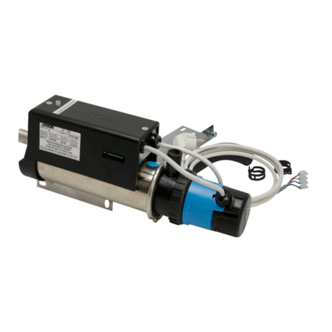
ATTENTION! If circulation pump (F 25)
is tted it must be connected on the
return pipe. Therubberconnectionsmust
besecuredwithbandclips.
AthinlayerofPermatexForm-a-Gasket
no.3shouldbeappliedtothejointsto
sealthembetweentherubberconnec-
tions.
ATTENTION! The heating system reaches
ahightemperaturewhenrunning.The
heatingpipesshouldbeinsulatedorbuilt
in to prevent the driver or passenger from
gettingincontactwiththemduringthe
journey.
ATTENTION! Copper pipes, joints or
water storage tanks should not be
used in the system. Aluminium pipes
alone are best. Do not mix different
metals as this can give rise to serious
corrosion damage.
CONNECTION TO THE
FRESH-WATER SYSTEM
Inorderthatthehotwaterheatershall
function,itmustbeconnectedtothevehi-
cle’sfreshwatersystem.
Thefreshwaterconnectionsarelocated
onbothsidesoftheboiler.Bluemarking
forincomingcoldfreshwaterandredfor
outgoinghotwater.
External safety valve with built-in
drain
AldeArticleNo.3010431Safety/Drain
valveshallbemountedonthecoldwater
hose into the heater.
DrillaØ.75in/16mmholeintheoorfor
thedrainhose,andthenscrewdownthe
safety/drainvalveintotheoor.
Mountthehoseconnection(F26)onthe
incoming nipple. Connect the safety/drain
valve to the hose connection.
ATTENTION! The safety/drain valve must
notbemountedhigherthanthehosecon-
nection.
Mounttheangleconnectionwithbuilt-in
bleedvalveonoutgoingconnection(F
27).
Thisshallbemountedinthesameway
asthehoseconnection.Mountthebleed
hose(F28)onthevalve’shosesleeve,
and then pull the hose out through the
oor.Thehoseshallbecutobliquelyat
a30°anglefromthedirectionoftravel
underthevehicle.Thehosemustnotbe
blocked.
OnlyusegenuineAldevalves.
LPG CONNECTION
Removetheprotectivecapfromthegas
pipeontheboiler(F29).
MaketheLPGinstallationtotheboiler
witha3/8”areconnection.
Whenlayingthepipe,rememberthatthe
boilerhastobedismountedforservice.
Theboilershouldbeconnectedtoan
LPGcylinderwithtype-approvedpressure
reducing valve and a pressure of
30mbar.
ATTENTION! National regulations must
be adhered to when installing LPG.
ELECTRICAL CONNECTION
12 VOLT DC (g E)
Connecttheextensioncable(E34)
betweenthecontrolpanelandtheLPG
boiler.
ATTENTION!Ifthereisnoglycolliquid
intheheatingsystem,waitbeforecon-
necting12Vtotheboiler.Thisissothat
theboilershallnotbestartedbymis-
takewithoutglycol.Thecablemustnot
beextended.Onlyusegenuinecables
fromAlde,whichareavailableinvarious
lengths.
Supplyof12voltstotheboilermustbe
directfromthebatteryviathevehicle’s
mainbreaker(E35)oraseparatebreaker
(theboilerconsumersabout70mAwhen
itisinstand-byorisswitchedoff).
Afuse(E36)of5Amustbemounted
closetothebattery.Theplusandminus
cablebetweenthebatteryandtheboiler
shallhaveanareaof16AWG1,3mm2up
to65feet/20metreslength(32feet/10m
forpositivecableand32feet/10mfor
minuscable).Withlongercablelengths,
theareamustbeincreasedto14,2mm
AWG.
Ifatransformerisusedinsteadofbattery,
itmustbeofgoodquality,givingproper
direct current and not pulsing direct cur-
rent.
ATTENTION.Donotclamporbind12
Vcablesorsensorcablestogetherwith
120Vcables.Itispreferablenottoplace
thecablesclosetoeachother.Ifthe
cablesarebundled,theriskofshutdown
increases.
120 VOLT ~
Connecttheboiler(electricalheatingele-
ment)securelyto120V~andsecurewith
a16Afusefor1,9kWelectricalheating
elements.Theboilermustbeprotectively
earthed.Theinstallationmustbecarried
outbyaqualiedpersonaccordingto
current national regulations. Only genuine
connectioncablefromAldemaybeused.
WARNING: 120V~mustbewellsepa-
rated from 12 V.
Fig E
34.Extensioncable.
35. Switch.
36.Mainfuse5A.
37. Connection plinth for 12 V in.
38.2-poleconnectionplinthonboiler.
39. Controlpanel3010614.
40. Circulation pump 12 V.
42.Boiler.
43. 10-poleconnectionplinth.
44. Battery12V.
FILLING THE HEATING
SYSTEM
Theheatingsystemshallbelledwith
aliquidmixtureconsistingofwaterand
“GRAS”Generallyrecognizedassafe
non-toxicpropyleneglycol.Preferablyuse
ready-mixedglycolofhighquality(with
inhibitor)intendedforaluminiumheat-
ingsystems.Whenusingconcentrated
glycol,themixtureshallbe60%water
and40%glycol.Iftheheatinginstallation
issubjectedtolowertemperaturesthan
-15°F/-25°C,theglycolcontentshouldbe
increased,however,notmorethan50%.
Thetankforhandlingtheliquidmustbe
absolutelyclean,andthepipesinthe
heatingsystemmustbefreefromcon-
tamination.Thisistopreventthegrowth
ofbacteriainthesystem.
Fillingthesystemiscarriedoutinthe
expansiontank,eithermanuallyorusing
Alde’sllingpump(1900811),whichboth
llsandbleedsthesystem.Whenlling
manually,theliquidmustbepouredin
slowlyuntilthelevelisabout.75in/1cm
abovetheMINlineonthetank.Bleedthe
system.Pourinsomemoreifthelevel
hasgonedownfrombleeding.Witha
newlylledheatingsystem,bleedatregu-
larintervalsduringtherstdaystheheat-
ing is running.
Forothercareoftheheatingsystem,see
User Instructions.
INSTALLATION CONTROL
The LPG system
• AlwayschecktheLPGinstallationfor
leakageafterinstallationorservice.
• Ifthereisleakage,localisetheleak
withleaksprayorsoapywater.
• ATTENTION!Anakedamemustnot
beusedwhenlookingforleaks.
• Checkthatthereductionvalveisatthe
right pressure.
The heating system
• Theheatingsystemshallbechecked
forleakswhentheentiresystemis
visible,i.e.,beforethextureshave
beenmounted.Checkscanbemadein
twoways.Eitherleakagecontrolwith
0.75–1.0barover15min-pressure
reductionmax.0.05bar,orbyllingthe
systemwithliquidandcheckingvisu-
ally.Noleakageofliquidisacceptable.
• Checkthatallhoseclipsaremounted
and correctly located.
Miscellaneous
• Checkthatthedraininghosesonthe
expansiontankandthedraincockfor
hotwaterarenotblocked.
• Checkthatueandhosesarecorrectly
inposition,andthathoseclipsare
mounted and fastened.
• Checkthattheboiler’sservicereport
hasthemanufacturingnumberand
installation date entered in it.
• Checkthattheyearontheboiler’s
dataplatehasacrossagainstit(when
mountingorduringrststart-up).


