manuals.online logo
Brands
  1. Home
  2. •
  3. Brands
  4. •
  5. Alderon Industries
  6. •
  7. Measuring Instrument
  8. •
  9. Alderon Industries Mini Power Post PRPT-00003 User manual

Alderon Industries Mini Power Post PRPT-00003 User manual

Mini Power Post™
Pump Connection Center | Model: PRPT-00003
Safety Guidelines
Step 4: Junction Box Wiring
Before proceeding with the installation or operation of this product,
read all instructions thoroughly, as well as complying with all federal,
state and local codes, regulations, and practices. This product must
be installed by qualied personnel familiar with all applicable local
electrical and mechanical codes. Refer to the National Electrical Code
(NFPA 70). Failure to properly install and test this product can result in
personal injury or equipment malfunction.
WARNING
Step 1: Install Post
QSG00009_Rev06_PRPT-00003_Mini Power Post | May 26, 2022 3:35 PM
Step 2: Remove Bottom Cover
Remove the bottom enclosure cover screw, slide the cover directly
downward (2A) and pull directly away from the enclosure (2B).
1) Route alarm float switch cable through Cable Grip A and firmly
tighten grip.
2) Route the underground feeder (UF) cable from the indoor alarm
panel through Cable Grip B and firmly tighten grip.
3) Route incoming pump power UF cable through Cable Grip D and
firmly tighten grip.
4) Connect wires in Cable Grip D to the pre-installed Wago
connectors on wires coming out of Cable Grip C as shown in the
diagram.
5) Connect wires coming in Cable Grip A to wires coming in Cable
Grip B as shown in the diagram.
Note: NEVER leave ground wire(s) exposed, use provided Wago
connectors for wire termination (see step 3).
QUICK START GUIDE
Step 3: Install Wire into Wago Connector
1) Lift tab(s) upward.
2) Insert wire(s) into slot.
3) Press tab(s) downward.
4) Make sure wire(s) are secured.
2B2A
WAGO
A
GREEN
BLACK
WHITE
BLACK
B
L
A
C
K
B
L
A
C
K
W
H
I
T
E
W
H
I
T
E
WHITE
GROUND
WAGO
WAGO
WAGO
WAGO
B
C
D
Determine location for the post in the
ground near a tank and drill access
holes for the float switch cables using
the customer supplied conduit/fittings or
Alderon’s riser connection kit. Route the
cables through access holes and wire
as described in step 4.
Note: Seal all conduits to prevent moisture and gases
from entering the post per local codes.
TO OPEN
WAGO
TO CLOSE
WAGO
Included with Product
Mini Power Post™- Features
Customer Support
Specications
▪ (1) Mini Power Post™; junction box pre-installed on post
▪ (1) Pre-installed, female, 15A pump power receptacle
(120VAC or 230VAC depending on part number)
▪ (4) Pre-installed cable grips
▪ (1) Junction box partition
▪ (5) Wago connectors; three pre-installed and two additional
Online
alderonind.com
Email
[email protected]
QR Code
Scan code for full product details
Enclosure: Outdoor, rated Type 3R
Certifications: CSA (US and Canada)
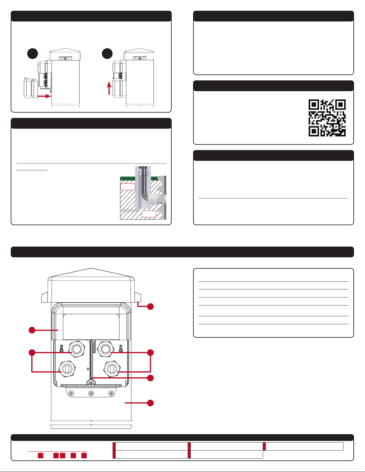
Step 5: Install Bottom Cover
Line up the bottom enclosure cover with the grooves (5A), then slide
directly upward (5B) until it meets the top of the enclosure so the screw
hole is lined up and replace the screw at the bottom of enclosure.
Backfill Area:
Once all steps of the installation are finished
and testing is complete, backfill the area you
dug for the post and riser in step 1.
After all wiring and installation steps have been completed, power the system
with incoming voltage(s) to match the pump and alarm voltages. Use the fea-
tures list and diagram below to perform a quick test of the system to make sure
it is working properly. Note: For the complete wiring, installation instructions,
or troubleshooting, refer to the user guide for this model by scanning QR code.
1 Vented Post Cap - Allows airow to prevent gases/condensation inside post
2Junction Box Enclosure - Pre-installed on post for easy wiring installation
3Cable Grips - Pre-installed for easy installation
4Partition - Separates high voltage from low voltage
5Pump Power Receptacle (not shown) - Pre-installed, female, 15A
(120VAC or 230VAC depending on part number)
6Post - Provides wire routing access and protection from water intrusion
7 QR Code (not shown)
- Scan code for additional product information (alderonind.com)
Backll
Area
Backll
Area
5A 5B
Pump Power Receptacle:
120VAC or 230VAC, 15A, 60Hz
(voltage depends on model/part number)
Pump Power: 120VAC or 230VAC, 13A or 15A, 60Hz
(voltage/amps depends on model/part number)
Step 6: Power System, Test and Backll
1Base Model
(Mini Power Post™ Standard)
3Alarm Options
(1-Zone Indoor Alarm, 15' Alarm
Float, and 15' Filter Switch)
5Riser Kit/Access Options (2.5"Riser Connection Kit)
2Pump Voltage (120VAC Pump) 4Pump Switch Options (15A, 15' Wide Angle)
SMP172B2
1 2 3 4 5
Model Number Nomenclature
1
2
3 3
4
6

Other manuals for Mini Power Post PRPT-00003

1

Other Alderon Industries Measuring Instrument manuals

Alderon Industries Power Post PPMS-0001 User manual

Alderon Industries

Alderon Industries Power Post PPMS-0001 User manual

Alderon Industries 7039 User manual

Alderon Industries

Alderon Industries 7039 User manual

Alderon Industries Mini Power Post MPMS-0001 User manual

Alderon Industries

Alderon Industries Mini Power Post MPMS-0001 User manual

Popular Measuring Instrument manuals by other brands

Eastron SDM630D quick start guide

Eastron

Eastron SDM630D quick start guide

Wonder INFLATOR DIGITAL user manual

Wonder

Wonder INFLATOR DIGITAL user manual

Omron H7CC-A Series manual

Omron

Omron H7CC-A Series manual

Bosch BEA 750 Original instructions

Bosch

Bosch BEA 750 Original instructions

Current Cost EnviR manual

Current Cost

Current Cost EnviR manual

Extech Instruments 382152 user manual

Extech Instruments

Extech Instruments 382152 user manual

Emerson Rosemount 3051SF Series quick start guide

Emerson

Emerson Rosemount 3051SF Series quick start guide

Sola FCL operating instructions

Sola

Sola FCL operating instructions

Kaiweets HT208A user manual

Kaiweets

Kaiweets HT208A user manual

Ohm-Labs 100 Series instruction manual

Ohm-Labs

Ohm-Labs 100 Series instruction manual

MICRO-EPSILON thermoMETER TIM 8 operating instructions

MICRO-EPSILON

MICRO-EPSILON thermoMETER TIM 8 operating instructions

EMH metering LZQJ-SGM instruction manual

EMH metering

EMH metering LZQJ-SGM instruction manual

TASKING iSYSTEM Infineon DAP Hardware user manual

TASKING

TASKING iSYSTEM Infineon DAP Hardware user manual

Bosch PLR 40 C instructions

Bosch

Bosch PLR 40 C instructions

ST UM2898 user manual

ST

ST UM2898 user manual

MBA MLA1000 operating instructions

MBA

MBA MLA1000 operating instructions

Tara LASER II user guide

Tara

Tara LASER II user guide

Tecsis E3907 operating manual

Tecsis

Tecsis E3907 operating manual

manuals.online logo
manuals.online logoBrands
  • About & Mission
  • Contact us
  • Privacy Policy
  • Terms and Conditions

Copyright 2025 Manuals.Online. All Rights Reserved.