Alderon Industries Mini Power Post MPMS-0001 User manual

USER GUIDE
MODEL NUMBERS:
MPMS-0001
MPMS-0002
Mini Power Post™Monitoring System
Pump Connection Center | Demand Dose
Alderon Industries™ | Patent Pending

Contents
Introduction................................................................................................................................................................. 3
Safety and System Guidelines ............................................................................................................................... 3
Product Included .................................................................................................................................................... 4
Features ................................................................................................................................................................. 5
Installation .................................................................................................................................................................. 6
Installing Post..................................................................................................................................................... 6, 7
Wiring..............................................................................................................................................................7, 8, 9
Tes tin g .................................................................................................................................................................... 9
Final Installation ..............................................................................................................................................10, 11
Basic System Functions ........................................................................................................................................... 12
System Power, Menu, and Event Displays........................................................................................................... 12
Pump Run and Total Gallons Pumped................................................................................................................. 13
Pump Alarms.................................................................................................................................................. 14, 15
Auxiliary Alarms ................................................................................................................................................... 16
System Functions | Events, Statistics, Settings, and Menu ...................................................................................... 17
Basic System Functions and Event Displays ....................................................................................................... 17
Statistic Value Displays ........................................................................................................................................ 17
Product Label Examples ...................................................................................................................................... 18
1.0, 2.0, 3.0, and 4.0 | Menu System - Main Menu............................................................................................... 19
1.0 | Main Menu - Resettable History................................................................................................................... 20
2.0 | Main Menu - Settings ................................................................................................................................... 21
3.0 | Main Menu - Lifetime History ....................................................................................................................... 22
4.0 | Main Menu - Model Name and Firmware..................................................................................................... 22
5.0 | Event Displays.............................................................................................................................................. 22
1.1 | Resettable History - Pump Run Stats........................................................................................................... 23
1.2 | Resettable History - Extended Pump Run Stats .......................................................................................... 24
1.3 | Resettable History - High Amp Stats............................................................................................................ 25
1.4 | Resettable History - Pump Float Stats ......................................................................................................... 26
1.5 | Resettable History - Power Loss Stats......................................................................................................... 26
3.1 | Lifetime History - Pump Run Stats ............................................................................................................... 27
3.2 | Lifetime History - Extended Pump Run Stats............................................................................................... 28
3.3 | Lifetime History - High Amp Stats ................................................................................................................ 29
3.4 | Lifetime History - Pump Float Stats.............................................................................................................. 30
3.5 | Lifetime History - Power Loss Stats ............................................................................................................. 30
Menu System Flow (text only) .............................................................................................................................. 30
General Operation.................................................................................................................................................... 31
Septic Tank Monitoring | Pump, Control, and Filter Switch Operated with Remote Alarm ................................... 31
Troubleshooting ........................................................................................................................................................ 32
Specications ........................................................................................................................................................... 33
Model Number Nomenclature................................................................................................................................... 34
Warranty Information ................................................................................................................................................ 35
Company Information ............................................................................................................................................... 36
Mini Power Post™ Monitoring System - USER GUIDE

Alderon Industries™ - Leading Edge Control Products | 3
Mini Power Post™ Monitoring System - USER GUIDE
Introduction
Use the Mini Power Post™ Monitoring System to make a professional and safe connection for power and oat switch wiring
connections to your on-site septic system. The Mini Power Post™ eliminates a 4" x 4" wood post and the exposed wires for a
safe, clean, and quick installation. This system can be used for a wide variety of demand dose applications, including but not
limited to: septic tanks, holding tanks, pump chambers, and water tanks. Available models include 120VAC and 240VAC.
The Mini Power Post™ Monitoring System serves as a junction box equipped with LED indicators (various colors) which is
connected to a remote alarm panel. The top of the enclosure cover changes color along with system function displayed text
on the OLED screen for easy troubleshooting information. Menu keys are provided to program settings and view data such as:
pump cycle counts, pump amps, elapsed time, total gallons pumped, alarm conditions, and more.
The system can be equipped with a Versa’larm™ alarm panel to connect a high level alarm oat switch, and/or lter switch
for remote notication of high level and lter service alarm conditions. A customer supplied sensor wire is used to make the
connections between the terminals on the remote alarm panel and the Mini Power Post™ enclosure.
Safety Guidelines
Before proceeding with the installation or operation of this product, read all instructions thoroughly, as well as complying with
all federal, state and local codes, regulations, and practices. This product must be installed by qualied personnel familiar with
all applicable local electrical and mechanical codes. Refer to the National Electrical Code (NFPA 70). Failure to properly install
and test this product can result in personal injury or equipment malfunction.
WARNING
1. DISCONNECT POWER when installing or servicing the product. Failure to disconnect all power sources could result in
serious injury or death.
2. NEVER enter a ooded space without proper Personal Protective Equipment (PPE). Always wear dielectric rubber boots
and other applicable protective equipment when water is on the oor and you must service an energized pump, alarm
system, or product.
3. DO NOT enter the water if the water level is higher than that of the protection your PPE offers or if your PPE is not
watertight.
4. DO NOT use this product with or near ammable liquids.
5. DO NOT install this product in locations classied as hazardous or in explosive atmospheres as dened by any applicable
electrical safety code.
System Guidelines
CAUTION: Before proceeding with the operation of this product, Alderon™ recommends changing the factory settings to
customize the system per application for desired operation. See page 21 for complete system settings information.
1. EXTENDED PUMP RUN TIME - Allowable time for pump to run continuously for longer than congured amount of time.
2. HIGH AMP LEVEL - Acceptable level of current sensed on the pump input during a pump run event.
3. GALLONS PER MINUTE - Perform manual test to determine value entered, when set to zero no statistics are displayed.

4 | Alderon Industries™ - Leading Edge Control Products
Mini Power Post™ Monitoring System - USER GUIDE
Product Included
This model includes: (1) Mini Power Post™ Monitoring System, (1) Pump Power Receptacle (120VAC or 240VAC, voltage
depends on model/part number), and (6) Wago connectors.
(1) Mini Power Post™ Monitoring System
The Mini Power Post™ comes with a 42.5-inch post to install in
the ground. The ventilated post cap, cable grips, and junction
box are all pre-installed to the post.
(2) Pump Power Receptacle
A female power receptacle is pre-installed, rated at 15 Amps.
Available in 120VAC or 240VAC models.
(3) Wago Connector
Six Wago connectors are included. Three are pre-installed on
the pump power receptacle and three are loose in enclosure, all
used for making wire terminations.
ADDITIONAL OPTIONS:
(4) Versa’larm™ Indoor Alarm Panel
The Versa’larm™ indoor alarm panel has options for remote
monitoring of one or two zones (sensors).
(5) Alarm Float Switch
The alarm oat switch is a typical sensor expected to be used
with the Versa’larm™ indoor alarm for liquid level monitoring.
(6) Pump Float Switch
The pump oat switch is used to control the pump directly. When
actuated the pump oat switch will pass power to the pump.
(7) Filter Switch
The lter switch is a typical sensor expected to be used with the
Versa’larm™ indoor alarm. The lter switch is used to activate
an alarm when a septic tank efuent lter needs to be serviced
and is universal to any brand of efuent lter that has a one-inch
through hole.
3
(120VAC Model Shown)
21
6
5
4 7

Alderon Industries™ - Leading Edge Control Products | 5
Mini Power Post™ Monitoring System - USER GUIDE
Features
Refer to the illustration below to reference the feature descriptions provided.
(1) Power On Indicator - Green LEDs will illuminate inside the top
cover of the enclosure to indicate that the unit is powered on. Note:
The power on LED indicators can be disabled in system settings, see
page 21.
(2) Alarm Beacon - During an alarm condition, the green power on
indicator will turn off and alarm LEDs (various colors) will illuminate,
ashing inside the top cover of the enclosure, see pages 12-17.
(3) Pump Run Indicator - When the pump is running under normal
conditions, the blue LED indicator will illuminate inside the top cover
of the enclosure. Note: The pump run LED indicators can be disabled
in system settings, see page 21.
(4) System LED Indicators - Multiple color indicators will illuminate
inside the top cover of the enclosure for visual indication of various
system events and/or alarm conditions. See pages 12-17 for detailed
information of system events or alarm conditions.
(5) OLED Display Screen - Displays system functions in addition
to the visual indication provided by the LED indicators inside the top
cover of the enclosure.
(6) Menu Keypad - Toggle between the system functions, program
settings, or view all lifetime data stored.
(7) Test Pushbutton - Used for quick access to lifetime pump run
event counter statistic, test the alarm LEDs, or exit the menu system.
The system MUST be in an idle state (solid green LEDs) to perform
testing. When pressed, the event statistic is displayed, then the alarm
LEDs will cycle between red, green, blue, and off, see page 18.
(8) Quick Snap Terminal Block - A four-position terminal block is
included to make fast and easy connections for: system power and
pump power. These wires are tied in series and pre-installed at the
factory .
(9) Vented Post Cap - Allows airow to prevent the build up of
gases and condensation inside the post.
(10) QR Code (not shown) - Scan code on bottom enclosure cover
which directs you to alderonind.com where additional information can
be found for the Mini Power Post™.
(11) Cable Grips - Pre-installed, making it easy to run wire in and out
of the enclosure. The grips create a liquid and gas tight strain relief
connection when securely fastened.
(12) Pump Power Receptacle (not shown) - A female, 15A, pump
power receptacle is pre-installed. Available in 120VAC or 240VAC
models.
(13) Post - Provides wire routing access for system power and pump
power while protecting from water intrusion.
1 2 34
5
6
7
13
8
9
11

6 | Alderon Industries™ - Leading Edge Control Products
Mini Power Post™ Monitoring System - USER GUIDE
Installation
DISCONNECT ALL POWER SOURCES WHEN INSTALLING OR SERVICING THIS PRODUCT. FAILURE TO
TURN OFF ALL POWER SOURCES COULD RESULT IN SERIOUS INJURY OR DEATH.
Installing Post
STEP 1: INSTALL POST
Determine the location for the post in the ground near a tank.
Drill access holes for the oat switch cables using the customer
supplied conduit/ttings or Alderon’s riser connection kit (refer
to step 2 below).
Run the direct burial power wires underneath the bottom of the
post as shown in the illustration to the right.
Note: Seal all conduits to prevent moisture and gases from
entering the post per local codes.
STEP 2: INSTALLING AN ALDERON RISER CONNECTION KIT
1. Determine location for access hole on the post. Drill access hole for the correct size terminal adapter (2.0" or 2.5" depending
on model / #2). Insert terminal adapter into access hole. On the inside of the post, use the lock nut (#1) to secure the terminal
adapter in place (use PVC cement to ensure proper bonding between the terminal adapter and post per local codes).
2. Insert PVC pipe (conduit / #3) into terminal adapter using appropriate cement for bonding.
3. Determine location on the riser to insert the conduit (2.0" or 2.5" depending on model). If your riser does not have a
pre-drilled hole for the conduit, you must drill a hole in the riser to accept the conduit. Insert conduit through the riser hole,
which is now attached with the post. Seal conduit to riser hole with silicone or per local codes.
4. Run the pump power, pump oat switch, and alarm oat switch cables through the PVC coupler (#5). Then continue through
the conduit and to the appropriate height inside the post for wiring. Take the 3-hole rubber grommet (#4) which has slits
next to the holes and insert cables, then insert the rubber grommet into the conduit.
5. Place the PVC coupler over the end of the conduit.
1 2 3 4 5
21 4 53
(Direct Burial Wires)

Alderon Industries™ - Leading Edge Control Products | 7
Mini Power Post™ Monitoring System - USER GUIDE
Installing Post (continued)
STEP 3: REMOVE BOTTOM COVER
The bottom enclosure cover is fastened by a single screw on
the bottom of the enclosure. Remove the screw and slide the
cover directly downward until sound chamber is cleared (3A)
and pull directly away from the enclosure (3B).
Wiring
INSTALLING WIRE INTO WAGO CONNECTORS
Before making wire connections and terminations, carefully
read this section for proper functions of both types of WAGO
connectors used with this product.
WARNING: Improper use of the connectors will cause damage
to components. DO NOT use mechanical tools to open or close,
hand usage only for proper installation and component integrity.
Wire Termination - Splice Connector WAGO (Figure 1):
1) Lift tab(s) upward.
2) Insert wire(s) into slot.
3) Press tab(s) downward.
4) Make sure wire(s) are secured.
Wire Connection - Quick Snap Terminal WAGO (Figure 2):
1) Press tab(s) outward. DO NOT open past a 40° angle to
avoid risk of breaking the tab(s).
2) Insert wire(s) into slot.
3) Press tab(s) inward.
4) Make sure wire(s) are secured.
TO OPEN
WAGO
TO CLOSE
WAGO
(Fig. 1)
3B3A
(Fig. 2)
TO OPEN
WAGO
TO CLOSE
WAGO
STEP 4: REMOVE POST CAP
Unscrew the fasteners on the left and right of the post cap
(4A) and pull directly upwards (4B). Keep the post cap off until
installation and testing are completed for wiring access.
4A
4B

8 | Alderon Industries™ - Leading Edge Control Products
Mini Power Post™ Monitoring System - USER GUIDE
Wiring (continued)
STEP 1: WIRING
The wiring diagram shows four terminals on the quick snap
terminal block that consists of two pairs of connections. Make
sure to read and review the connector examples on page 7 for
proper installation prior to wiring.
Note: The quick snap terminal block, is herein referred to as
“terminal” for instruction purposes. The installation example
shown is for 120VAC, for 240VAC installation the neutral (N)
wire would be replaced by line connection (L2) and white wire
would include a red band to indicate the wire is hot.
1) The alarm and pump power connections are factory wired
from the terminals and pre-installed female receptacle in
the middle cable grip. The wires are terminated by the
pre-installed Wago connectors which are separated into
line, neutral, and ground connections.
2) The rst cable grip, starting at the right, has a cable grip
divider allowing for two cable sources to be brought into
the enclosure. The top side of the cable grip is used for
the both the alarm and pump power, attached in series.
The line (L1), neutral (N), and ground (G) wires each get
terminated by the Wago connectors. After bringing in the
cables, rmly tighten the cable grip by twisting clockwise
until securely fastened.
If the system is equipped with a remote alarm panel, high level
alarm oat switch, and/or lter switch, continue with the steps
below before proceeding to power connection or testing.
3) The rst cable grip, starting at the right, has a cable grip
divider allowing for two cable sources to be brought into
the enclosure. The bottom side of the cable grip is used
for the customer supplied sensor wire. Use the provided
Wago connectors to terminate the black (1C), red (1B),
and white (1A) wires. After bringing in the cables, rmly
tighten the cable grip by twisting clockwise until securely
fastened.
4) The third cable grip, on the left, has a cable grip divider
for the sensor wires. The high level alarm oat switch
black and white wires are paired with the black and
common sensor wires (1C and 1A). The lter switch black
and white wires are paired with the red and common
sensor wires (1B and 1A). After bringing in the cables,
rmly tighten the cable grip by twisting clockwise until
securely fastened.
5) NEVER leave ground wire(s) exposed, use provided
Wago connector for wire termination.
Note: A sensor wire is connected to the terminal blocks on the remote
alarm panel and wired in pairs to the high level alarm oat switch and
lter switch inside the enclosure of the Mini Power Post™ as described
above. The alarm panel provides remote notication of alarm conditions.
WAGO
WAGO
WHITE
BLACK
WHITE/RED
GROUND
WHITE
BLACK
BLACK
BLACK
WHITE/RED
GROUND
1A 1B 1C
RED
BLACK
WHITE
BLACK
WHITE
BLACK
L1
N
G
Power Wiring
(steps 1 and 2)
L1
N
G
Factory Wired
Factory Wired
Field Wired
Factory Wired
Factory Wired
Field Wired
Field Wired
Factory Wired
Alarm Power
Pump Power
Factory Wired
N/L2
L1
L1

Alderon Industries™ - Leading Edge Control Products | 9
Mini Power Post™ Monitoring System - USER GUIDE
Testing
Make sure all steps of the installation and wiring process is
completed and there is power to the product.
STEP 1: TEST ALARM LEDs
Press the test pushbutton on the front of the enclosure, the
lifetime pump run event counter statistic should display, then
alarm LEDs should illuminate while cycling between red, green,
blue, and off. The OLED screen should display a TESTING
(COLOR) event to match the respective LEDs after the event
statistic is displayed.
Note: When activated, system test will exit the menu system
without saving and disable the menu system. Any events that
are active while system test starts will not be shown, but will be
tracked normally. Any newly activated event will deactivate the
system test event.
STEP 2: TEST PUMP AND PUMP FLOAT SWITCH
The pump power is factory wired to the terminals and attached
in series to the alarm power, terminated by Wago connectors.
Make sure the tank has water to perform the pump and pump
oat switch testing. Activate the pump oat switch, the blue
LEDs should illuminate and the OLED screen should display a
PUMP RUN event and the pump amps are displayed.
Note: Record the pump amps if changing the high amp level
setting in the main menu. See page 21 for detailed information.
STEP 3: RECOMMENDED SYSTEM SETTINGS
Alderon™ recommends changing the factory settings for: high
amp level, extended pump run time, and gallons per minute.
See page 21 for detailed information.
STEP 4: TEST WEEKLY
To ensure the product is functioning properly, test once a week.
Note: If using a remote alarm panel, high level alarm oat switch, and/or lter switch;
refer to the product instructions for additional installation and testing information.
STEP 2: PIGGYBACK PLUG CONNECTIONS
1) Plug the male end of the piggyback plug on the pump switch
power cable into the pre-installed female power receptacle
inside the post (2A).
2) Plug the male end of the pump power cable into the female
end of the piggyback plug on the pump switch power cable
(2B) from step 2-1.
Note: The installation example shown is for a 120VAC system,
use the same process when connecting 240VAC piggyback
power cables.
2B
2A
Pump Switch
Piggyback Plug
Power Cable
Pump
Power Cable
(120VAC Example Shown)
Pre-Installed
Female
Power Receptacle
Wiring (continued)

10 | Alderon Industries™ - Leading Edge Control Products
Mini Power Post™ Monitoring System - USER GUIDE
STEP 2: INSTALL POST CAP
To replace the cap, position so the text FRONT (with arrows)
on the underneath portion is facing the front of the post and
align the fastener holes on the left and right of the cap to the
holes on the post (2A). Fasten the screws to properly secure the
cap (2B). The cap prevents water intrusion and allows airow to
prevent the build up of gases and condensation inside the post.
STEP 1: INSTALL BOTTOM COVER
Place the bottom of enclosure back on, lining up with the
grooves (1A). Then slide the bottom piece upward (1B) until it
meets the top piece and screw hole is lined up with the boss.
Replace the screw at the bottom of the enclosure.
Final Installation
1A 1B
2B2A
FRONT

Alderon Industries™ - Leading Edge Control Products | 11
Mini Power Post™ Monitoring System - USER GUIDE
STEP 3: BACKFILL
Make sure all steps of the installation, wiring, and testing are
complete. Take the dirt/soil removed and backll the area for
the post, riser, and direct burial power wiring.
Backll
Area
Backll
Area
Final Installation (continued)

12 | Alderon Industries™ - Leading Edge Control Products
Mini Power Post™ Monitoring System - USER GUIDE
Basic System Functions
System Power, Menu, and Event Displays
SYSTEM ON AND PUMP OFF
When the system is powered and the pump is off under normal
operating conditions, the green LEDs will illuminate inside the top
cover of the enclosure to indicate there is power to the system.
When the system is idle and there has been no activity or key
pressed for approximately 70 seconds, the OLED display screen
will be blank.
CAUTION:
Before proceeding with the operation of this
product, Alderon™ recommends changing factory settings to
customize the system per application for desired operation. See
page 21 for complete system settings information.
The Mini Power Post™ Monitoring System includes visual indication provided by the various color LEDs that illuminate inside
the top cover of the enclosure along with displayed text on the OLED screen. This section outlines the basic system functions
for: system power, menu access, pump run event, pump alarm events, auxiliary alarm events, and data log center information.
For remote notification of a high level or filter alarm event, a Versa’larm™ indoor alarm panel must be used with the system.
WAKE SYSTEM
To wake the OLED display screen, press any arrow key (up, down, left, or right) on the menu keypad and SYSTEM NORMAL
will appear (Figure 1). Turn off the green power on LEDs in the settings menu, see page 21 for detailed information.
SYSTEM MENU
To access the system menu, press MENU on the menu keypad and RESETBLE HISTORY will appear (Figure 2). Pressing the
MENU button from a blank screen will also access the main menu. To view the list of menu screens and system settings, see
pages 19-22 for detailed information.
(Fig. 1) (Fig. 2)

Alderon Industries™ - Leading Edge Control Products | 13
Mini Power Post™ Monitoring System - USER GUIDE

Pump Run and Total Gallons Pumped
PUMP RUN - TOTAL GALLONS PUMPED (TGP)
When the pump is running under normal operating conditions,
the system will record total gallons pumped. This calculation is
based on the gallons per minute (GPM) setting, factory set to
zero. Use the menu keypad to access the information below while
the pump is running or when the system is idle. See pages 21,
23, 24, 27, and 28 for detailed information and display screens.
▪ TGP Stats - Records total gallons pumped. When the
maximum displayed gallons are exceeded, the gallons
will restart at zero (maximum value of 9999999G).
▪ GPM Setting - Use the menu keypad to change the
setting. If the GPM is set to zero, the TGP stats will not
be displayed on the OLED screen. See page 21 for
detailed information.
▪ Manually Calculate GPM Value to Program
i. Measure water level in tank.
ii. Run pump for designated amount of time.
iii. Measure new water level in tank.
iv. Calculate results from test.
▪ All Data Stored in Two Formats
i. Resettable; Reset all data to zero.
ii. Non-Resettable; All lifetime data is stored.
PUMP RUN
When the pump is running under normal operating conditions, the
blue LEDs will illuminate inside the top cover of the enclosure.
The OLED screen will display a PUMP RUN event and the pump
amps are displayed. Use the menu keypad to access the pump run
information below while the pump is running or when the system
is idle. Turn off the blue pump run LEDs in the settings menu. See
pages 21, 23, and 27 for detailed information and display screens.
▪ Pump Run Event Counter - Records each pump event.
▪ Pump Run Elapsed Time - Records the total run time of
each pump run event including: last, average, maximum,
and minimum of the last 10 pump cycles.
▪ Pump Amp Detection - Records the amps each time a
pump event occurs including: last, average, maximum,
and minimum of the last 10 pump cycles.
▪ Pump Float Event Counter - Records each time the
pump float is activated during a pump run event.
▪ Pump Run Settings - Use the menu keypad to change
the factory settings for: pump run LED turn on or off and
gallons per minute. See page 21 for detailed information.
▪ All Data Stored in Two Formats
i. Resettable; Reset all data to zero.
ii. Non-Resettable; All lifetime data is stored.

14 | Alderon Industries™ - Leading Edge Control Products
Mini Power Post™ Monitoring System - USER GUIDE
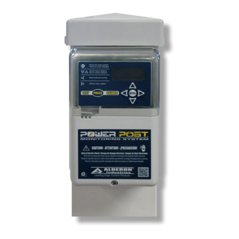
Pump Alarms
EXTENDED PUMP RUN ALARM
An extended pump run alarm event will occur when the pump
has run continuously for longer than the congured amount of
time, factory set to 30 minutes.
The red and blue LEDs will illuminate inside the top cover of
the enclosure and alternate every second. The OLED screen
will display an EXT PUMP ALARM event. The alarm condition
will clear once the system no longer detects an extended pump
run event.
Use the menu keypad to access the extended pump run alarm
information below while the pump is running or when the system
is idle. See pages 21, 24, and 28 for detailed information and
display screens.
▪ Extended Pump Run Event Counter - Records each
extended pump run event.
▪ Extended Pump Run Elapsed Time - Records the total
run time of each extended pump run event including: last,
average, maximum, and minimum of the last 10 extended
pump run cycles.
▪ Extended Pump Run Amp Detection - Records the
amps each time an extended pump run event occurs
including: last, average, maximum, and minimum of the
last 10 pump cycles.
▪ Extended Pump Run Setting - Use the menu keypad
to change the factory setting of 30 minutes. See page 21
for detailed information.
▪ Extended Gallons Per Minute (GPM) Setting - Factory
set to zero, use the menu keypad to change the setting.
If the GPM is set to zero, the total gallons pumped stats
will not be displayed on the OLED screen.
▪ All Data Stored in Two Formats
i. Resettable; Reset all data to zero.
ii. Non-Resettable; All lifetime data is stored.
‹ ‹ ‹ Alternating LEDs › › ›

Alderon Industries™ - Leading Edge Control Products | 15
Mini Power Post™ Monitoring System - USER GUIDE
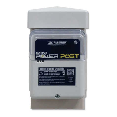
Pump Alarms (continued)
HIGH AMP ALARM
A high amp alarm event will occur when the current sensed on
the pump input during a pump run event is equal to or greater
than the congured high amp threshold setting, factory set to
15 Amps.
The high amp alarm will not be activated during the initial startup
of a pump run event, even if the high amp threshold is exceeded
to account for high amp draw during pump startup. The high
amp threshold is deactivated as soon as the current sensed on
the pump is less than the programmed setting.
The purple and blue LEDs will illuminate inside the top cover of
the enclosure and alternate every second. The OLED screen
will display a HIGH AMP ALARM event. The alarm condition
will clear once the system no longer detects a high amp event.
Use the menu keypad to access the high amp alarm information
below while the pump is running or when the system is idle.
See pages 21, 25, and 29 for detailed information and display
screens.
▪ High Amp Event Counter - Records each high amp
event.
▪ High Amp Elapsed Time - Records the total run time of
each high amp event including: last, average, maximum,
and minimum of the last 10 extended pump run cycles.
▪ High Amp, Amp Detection - Records the amps each
time a high amp event occurs including: last, average,
maximum, and minimum of the last 10 pump cycles.
▪ High Amp Setting - Use the menu keypad to change the
high amp factory setting of 15 Amps. See page 21 for
detailed information.
▪ All Data Stored in Two Formats
i. Resettable; Reset all data to zero.
ii. Non-Resettable; All lifetime data is stored.
‹ ‹ ‹ Alternating LEDs › › ›

16 | Alderon Industries™ - Leading Edge Control Products
Mini Power Post™ Monitoring System - USER GUIDE
Auxiliary Alarms
POWER LOSS ALARM
When the internal AC power supply is lost, the system
conserves power until the statistics have been saved before
a power loss alarm event is activated. There will be no LEDs
illuminated inside the top cover of the enclosure. The OLED
screen will display a PWR LOSS ALARM event before the
screen goes blank.
Use the menu keypad to access the power loss alarm
information below after the system has been restored and is
idle. See pages 26 and 30 for detailed information and display
screens.
▪ Power Loss Alarm Event Counter - Records each
power loss event.
▪ All Data Stored in Two Formats
i. Resettable; Reset all data to zero.
ii. Non-Resettable; All lifetime data is stored.

Alderon Industries™ - Leading Edge Control Products | 17
Mini Power Post™ Monitoring System - USER GUIDE
System Functions | Events, Statistics, Settings, and Menu
The basic system functions with displayed text and corresponding LED indicator colors for system events are listed below. Refer
to the value charts for additional system displays of statistical data and descriptions for each.
Mini Power Post™ Monitoring System | Demand Dose - System Functions and Event Displays
ENCLOSURE LED INDICATOR
SYSTEM FUNCTION DISPLAYED TEXT DESCRIPTION OF SYSTEM FUNCTION
Green Continuous SYSTEM NORMAL
System is Normal
Blue Continuous PUMP RUN
Pump is Running Normal
Red/Blue Alternating EXT PUMP ALARM
Alarm - Pump is Running Continuously; Check Pump Float or Broken Pipe
Purple/Blue Alternating HIGH AMP ALARM
Alarm - Pump is Drawing High Amps; Check Pump and Pump Blockages
White/Cyan Alternating UI ERROR (event not displayed)
Faceplate or OLED Screen not connected to Circuit Board; Check Ribbon for Proper Connection
Basic System Functions and Event Displays
The Mini Power Post™ Monitoring System includes visual indication provided by the various color LEDs that illuminate inside
the top cover of the enclosure along with displayed text on the OLED screen. This section outlines system function screen
displays for: system normal, main menu, resettable and lifetime history data log center, settings, system events, and model
name with firmware version.
The charts in this section show how the statistical data is displayed on the OLED screen for amps and elapsed time meter.
Statistic Value Displays
Amp Statistic Statistic Prex
Last AMP
Average AvA
Maximum MxA
Minimum MnA
Amp Value Format Description
--.- No amp data
xx.x Amps to nearest 0.1A
> 20 Amps exceed maximum detectable current
Elapsed Time
Statistic
Statistic Format
(seconds)
Statistic Format
(minutes)
Statistic Format
(hours)
Statistic Format
(out of range)
Last SEC xxx MIN xxx HRS xxx HRS >999
Average AvgS xxx AvgM xxx AvgH xxx AvgH >999
Maximum MaxS xxx MaxM xxx MaxH xxx MaxH >999
Minimum MinS xxx MinM xxx MinH xxx MinH >999
Note: The statistic format for elapsed time will display in seconds and minutes up to 599 for each, hours will display up to 999,
and hour values greater than 999 will display “out of range” (>999).

18 | Alderon Industries™ - Leading Edge Control Products
Mini Power Post™ Monitoring System - USER GUIDE
Product Label Examples
MENU LEGEND and KEYPAD
The menu legend and keypad are located on the product label,
see the examples to the right and detailed text version below.
1) Press the MENU button to access the main menu screen,
accept settings questions, or save changes.
2) Press the DOWN or UP arrows to scroll through the list of
menu options and to set or select system options.
3) Press the LEFT arrow to go back without saving from any
menu or settings option screen.
4) Press the RIGHT arrow to select menu options or to enter
the next value in the settings option screens.
TEST PUSHBUTTON
The test pushbutton is used for quick access to lifetime pump
run event counter statistic, test the alarm LEDs, or exit the menu
system.
1) Perform a system test weekly by pressing the PRESS
pushbutton, the system MUST be in a system normal or
idle state (solid green LEDs). The lifetime pump run event
counter statistic should display until the button is released,
or for two seconds, whichever is greater. Then, the alarm
LEDs should illuminate for two seconds each while cycling
between red, green, blue, and off. The OLED screen
should display a TESTING (COLOR) event to match the
respective LEDs after the event statistic is displayed.
2) Pressing the PRESS pushbutton after the system test has
started will restart the test sequence from the beginning at
the lifetime pump run event counter statistic.
Note: When activated, system test will exit the menu system
without saving and disable the menu system. Any events that
are active while system test starts will not be shown, but will be
tracked normally. Any newly activated event will deactivate the
system test event.

Alderon Industries™ - Leading Edge Control Products | 19
Mini Power Post™ Monitoring System - USER GUIDE
The menu system contains several menus and sub-menus. Use the menu keypad to navigate through active events, resettable
and lifetime history statistics, and system settings which can be programmed to customize the system per application.
Menu System
MAIN MENU - Blank Screen
When the system is idle and there has been no event activity or
key pressed for at least 70 seconds, the OLED screen will be
blank. Press any arrow key (up, down, left, or right) to wake the
system, SYSTEM NORMAL will appear.
MAIN MENU - System Normal
From the SYSTEM NORMAL screen, press the MENU button to
access the main menu and RESETBLE HISTORY will appear.
Pressing the MENU button from a blank screen will also access
the main menu.
1.0 | MAIN MENU - Resettable History
From the RESETBLE HISTORY screen, press right arrow key
for menu to view and clear statistics (see page 20). Press down
arrow key to the SETTINGS screen.
2.0 | MAIN MENU - Settings
From the SETTINGS screen, press right arrow key for menu
to enter password and program system settings (see page 21).
Press down arrow key to the LIFETIME HISTORY screen.
3.0 | MAIN MENU - Lifetime History
From the LIFETIME HISTORY screen, press right arrow key for
menu to view statistics (see page 22). Press down arrow key to
the MODEL / FIRMWARE screen.
4.0 | MAIN MENU - Model Name and Firmware Version
From the MODEL / FIRMWARE screen, press down arrow key
to bring you back to the RESETBLE HISTORY screen.
Note: The down arrow key will cycle through all the main menu
options until a specic option is selected using the right arrow
key as displayed on the screen and described above. Press the
test pushbutton to exit the menu system.

20 | Alderon Industries™ - Leading Edge Control Products
Mini Power Post™ Monitoring System - USER GUIDE
Menu System (continued)
1.0 | MAIN MENU - Resettable History
From the RESETBLE HISTORY screen, press right arrow key
to access the menu for event statistics and then press down
arrow key for the available events within this menu.
1.1 Pump Run Stats
1.2 Extended Pump Run Stats
1.3 High Amp Stats
1.4 Pump Float Stats
1.5 Power Loss Stats
See pages 23-26 for individual stats of each event type listed
above and data stored in the system. Each resettable history
event stat has a clear history function. The non-volatile memory
allows all settings and statistics to be retained during power
outages.
Note: The down arrow key will cycle through all the resettable
history menu options until a specic option is selected using the
right arrow key as displayed on the screen. Press the left arrow
key to exit from any screen. Press the test pushbutton to exit the
menu system.
Other manuals for Mini Power Post MPMS-0001
1
This manual suits for next models
1
Table of contents
Other Alderon Industries Measuring Instrument manuals
Popular Measuring Instrument manuals by other brands

PeakTech
PeakTech 3432 manual

Precision Digital Corporation
Precision Digital Corporation Trident Series instruction manual

Endress+Hauser
Endress+Hauser CNGmass DCI operating instructions

ATAGO
ATAGO PAL-HIKARi 15 instruction manual

Siemens
Siemens SIPROCESS GA700 operating instructions

Kamstrup
Kamstrup MULTICAL 803 Technical description