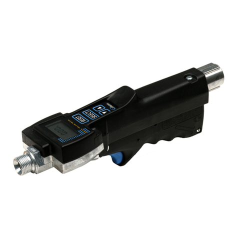
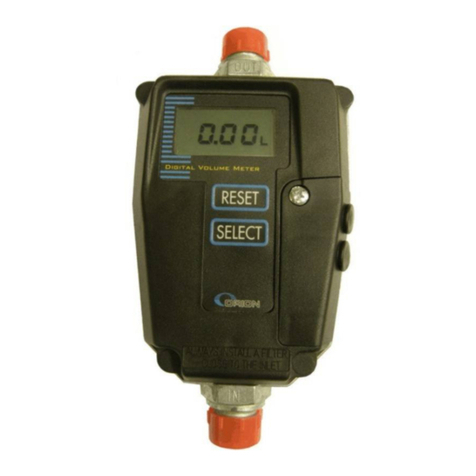
Alentec & Orion 24700 User manual

USER MANUAL / BRUKSANVISNING / MANUEL D’UTILISATION / BEDIENUNGSANLEITUNG / MANUAL DE INSTRUCCIONES
Manual 24700GBM_ARC6 2014-10-17
Part
No.
/
Réf.
/
Art.
Nr.
/
Cód.:
24700
HOSE-END METER, STANDARD
HANDMÄTARE, STANDARD

Manual 24700GBM_ARC6
2(8)
1.
INTRODUCTION 3
2.
MECHANICAL INSTALLATION 3
3.
STRAINER 3
4.
BATTERIES 3
5.
HOW TO USE 3
5.1.
C
HECK BEFORE USE
3
5.2.
D
ISPENSE FLUID
4
5.3.
“T
RIP
”
COUNTER
4
5.3.1.
Check the “Trip” counter.................................................................................................................. 4
5.3.2.
Reset the “Trip” counter................................................................................................................... 4
5.4.
“T
OTAL
”
COUNTER
4
5.4.1.
Check the “Total” counter ................................................................................................................ 4
5.4.2.
Reset the “Total” counter ................................................................................................................. 4
5.5.
C
ALIBRATION
5
5.5.1.
Calibration possibility....................................................................................................................... 5
5.5.2.
Calibration procedure....................................................................................................................... 5
5.6.
U
NIT USED FOR MEASURING
6
5.6.1.
How to set the unit............................................................................................................................. 6
5.7.
LCD
SEGMENT TEST
7
5.8.
B
ATTERY STATUS
7
6.
SPARE PART LIST 7
7.
TECHNICAL SPECIFICATION 8

Manual 24700GBM_ARC6
3(8)
1. Introduction
The Hose-End meter (standard model) 24700 is used to measure the volume of fluid filled in an object. The meter is based on the
“oval-gear” Principe. It uses permanent magnets and REED-switches as signal pickup.
The integrated valve is pressure balanced to enable a smooth flow control almost independent of fluid pressure.
It is manufactured with small tolerances to assure a high degree of accuracy over a wide range of flow and viscosity.
To conserve battery the meter goes into sleep mode after 1 minute of inactivity. All data is stored so if it is waken up again it
continues from where it was.
2. Mechanical installation
The meter is delivered in an environmental adapted paper box together with additional parts according to the demand.
The inlet of the meter is female G1/2 with an O-ring groove to suit the Alentec&Orion AB original line of swivels. Use liquid
sealant if additional sealant is needed.
The outlet of the meter is male G1/2 with inside 60° cone to suit the Alentec&Orion AB line of original outlet equipment or other
standard hydraulic 60° cone adapters. Use liquid sealant if additional sealant is needed.
Note! –Do not use Teflon tape or other solid thread sealants and do not use excessive torque for the
fittings!
3. Strainer
To maintain a high grade of accuracy, keep the valve closing properly and minimise wear solid contaminations has to be kept
away. For this purpose the 24700-meter is equipped with an efficient strainer cup in the flow inlet. This strainer should be
checked regularly and cleaned when needed. To clean it remove the inlet swivel and the pull out the strainer.
4. Batteries
2 pieces of AAA 1,5 batteries is used as power source. They are placed in a battery holder and secured by holder it self and a
“rubber band” for extra security. The battery holder is contained in the rear part of the meter handle and secured in place by
“foam strips”. To get access to the battery holder loosen the screw at the lower-back end of the control handle and fold the handle
out.
5.
How to use
Always read the manual before using the meter.
5.1. Check before use
The meter will probably be in sleep mode when you grab it so press the RESET or SELECT button
to wake it up. Then the display should look like this.

Manual 24700GBM_ARC6
4(8)
Dispense fluid
To dispense fluid press the <RESET> or <SELECT> button to wake the meter up if it is in sleep mode or just continue the
last dispense. If a new dispense is to be started press <RESET> button after wake up to zero the meter.
5.2. “Trip” counter
The meter is equipped with a “Tripp” counter that shows the accumulated volume of fluid dispensed since it was last
“RESET”. The “Trip” counter can be zeroed, “re-set”.
5.2.1. Check the “Trip” counter
When the meter is in normal dispense mot the TRIP-counter can be shown by pressing the <Select> button.
Normal dispense mode.
Press <SELECT>. May need to be pressed more than once depending on
mode. The total volume (in whole units) since the last re-set is shown.
5.2.2. Reset the “Trip” counter
When the meter is showing the TRIP-counter it could be se-set. This only re-sets the TRIP-counter nothing else.
Press <SELECT>. May need to be pressed more than once depending on
mode. The total volume (in whole units) since the last re-set is shown.
Press <RESET> to zero the TRIP-counter.
5.3. “Total” counter
The meter is equipped with a “Total” counter that shows the accumulated volume of fluid dispensed since the meter was put
into use. The “Total” counter cannot be zeroed (RESET)
5.3.1. Check the “Total” counter
When the meter is in normal dispense mode the TOTAL-counter can be shown by pressing the <Select> button.
Normal dispense mode.
Press <SELECT>. May need to be pressed more than once depending on
mode. The total volume (in whole units) since the last re-set is shown.
5.3.2.
Reset the “Total” counter
The “Total” counter cannot be re-set to zero.

Manual 24700GBM_ARC6
5(8)
5.4. Calibration
Normally the meter does not need calibration if it is used for normal workshop oils but if fluids with high or low viscosities
or high or low flows are used calibration may be needed.
Also calibration may be needed after a long time of use especially if dirt is present in the fluid.
To make a usable calibration some rules has to be followed.
1. The calibration works for any volume but recommended is at least 1 L.
2. The measuring vessel must be of laboratory grade and absolutely empty. A prior
dispense can easily leave 0.1L or more even if it appears empty. Put the vessel upside down for a while or clean it
before each calibration dispense.
A really accurate calibration can only be made by a scale and knowing the density of the fluid.
3. When a dispense is done all air has to be removed from the fluid. This can take a long time. It can be accelerated by
vacuum. If a scale is used the air does not matter.
5.4.1. Calibration possibility
The meter can be calibrated +/- 10%. If this is not enough the meter chamber should be replaced.
If the calibration factor exceeds this during calibration the display will show an error message “E3” for a while.
Because of that this meter normally gives an accuracy of +/- 0,5% directly from stock for normal workshop oils and
has proved to maintain the accuracy after several 100000 of litres the most probable causes for this error is
Bad measuring vessel.
Measuring vessel not empty from the beginning.
Air in the oil not evacuated properly.
Wrong measured volume input.
5.4.2. Calibration procedure
The calibration process is semiautomatic and started by entering configuration mode.
Press <RESET> and <SELECT> buttons simultaneous
and hold them down for 5 s. If successfully done the
display will change to this, showing that the meter is in
configuration mode. Now release the buttons.
Then press <SELECT> button to get into “Set unit”
mode. The display will change to.
Then press <SELECT> button again to get into
“Calibration” mode. The display will change to.
Then press <RESET> button to start the calibration
process. The display start switching between “dISP” and
“0.0000”.
◄▬►
Now start dispensing. It does not matter how much you
dispense but to get a good calibration at least 1L is
recommended. During the dispense it will switch
between “dISP” and the dispensed volume.
◄▬►
When the decided volume is reached, in this case
1.5639L, release the handle of the meter so the flow
stops.
◄▬►

Manual 24700GBM_ARC6
6(8)
Then press <SELECT> and the display will move on to
received volume input. The first figure will “blink” to
show that it is changeable. Press <RESET> to change
the value press <SELECT> to change to the next figure.
◄▬
►
In this example we received 1.6852 L so we move to
second figure with <SELECT> and change it from 5 to
6 with <RESET> move to third figure and change it
from 6 to 8 and so on.
◄▬
►
When the last figure is blinking and <SELECT> is
pressed the display will change to show the calculated
calibration factor. If <RESET> is pressed the new
calibration is cancelled.
If <SELECT> is pressed the calibration is saved and
then the meter goes back to normal dispense mode. The
calibration is done.
▬
►
If the calculated factor exceeds +/- 10% the error
message “E3” will be shown for a while and then it will
go back for a new calibration dispense.
▬
►
5.5.
Unit used for measuring
The meter can be set to use either [L]itre, [G]allon, [P]int or [Q]uater. The unit used is shown after the value.
5.5.1. How to set the unit
Press <RESET> and <SELECT> buttons simultaneous
and hold them down for 5 s. If successfully done the
display will change to this, showing that the meter is in
configuration mode. Now release the buttons.
Press <SELECT> button to get into “Set unit” mode. The
display will change to.
Scroll through the different units using the <RESET>
button. L, G, P, Q, L,…… . When the wanted unit is
shown release all buttons and wait. The will save and go
back to “ConF” after a short time.
WAIT!
To get back to normal operation mode wait a short time
or press <RESET> button. When the display looks like
this it is done.

Manual 24700GBM_ARC6
7(8)
5.6. LCD segment test
The LCD can be checked by putting the meter in normal dispense mode.
Normal dispense mode.
Press <RESET> and the meter will do a re-set and
show all the segments of the LCD for a short while.
5.7. Battery status
The status of the batteries is shown on the display.
Batteries OK.
Batteries LOW, needs to be replaced. Replace with 2
pieces of 1,5 IEC LR03 / ANSI AAA batteries. Be
sure to put the new ones in the correct direction!
6. Spare part list
Pos
Spare part / Reservdel
Part Nr
1
Cover with electronic
234 60 78
2
Overlay for 2 button
204 58 90
3
Support for electronics
204 55 94
4
Battery holder
234 60 79
5
Meter chambe
r, complete with oval gear
244 58 19
6
Trigger handle, compl.
244 57 07
7
1.5V Battery LR03/AAA, 2 pieces
required
234 60 77
8
Inlet strainer
224 58 17
9
Battery support
204 57 49
10
Valve body kit ass. Complete with all
sealings and safety plugs.
244
59 09

Manual 24700GBM_ARC6
8(8)
7. Technical specification
Type: Oval gears on steel shafts in a casted metal chamber with pressure drain grooves.
Pickup system: 4 pieces of permanent magnets on one of the gears configured North-South-North-South to eliminate
magnetic history. The rotation is detected through the measuring chamber lid by a REED-switch on the
electronic printed circuit board eliminating the risk for shaft leakage.
Materials: Measuring chamber = Zinc, Handle frame/Valve housing = Aluminium, Gears = Vectra®, Casing =
Fibreglass reinforced Delrin®, Gear shafts = stainless steel, Overlay = Polycarbonate with 3M
adhesive, Valve spindle = Brass and Nitrile O-rings.
The meter complies with the RoHS directive.
Output: LCD display with 4 figures and 1 decimal (XXXX.X), battery check symbol, Trip, Total and Unit.
Data storage: Static E2RAM for set-up, Trip counter and Total counter
Power supply: 2 pieces of 1.5V standard battery, IEC LR03 / ANSI AAA
Fluid connections: Inlet female G1/2 with O-ring groove and inlet strainer.
Outlet male G1/2 with an inside 60° cone.
Pressure: Max working pressure = 5MPa (50 bar).
Min burst pressure = 15MPa (150 bar)
Flow range: Normal = 1.5 to 15 L/min.
Possible = 0.5 to 25 L/min (Dependant of fluid)
Viscosity range: 8-2000 cSt.
Accuracy: From stock and normal fluids better than +/- 1%. After calibration within 5cl.
Weight: 0.5 kg
Table of contents
Other Alentec & Orion Measuring Instrument manuals
Popular Measuring Instrument manuals by other brands

Agilent Technologies
Agilent Technologies InfinityLab LC Series user manual

Knick
Knick 830 R manual

Larson Davis
Larson Davis 820 Technical reference manual

SIGLENT
SIGLENT SHA850A quick guide

Keysight Technologies
Keysight Technologies FieldFox N9913A Configuration guide

3M
3M Dynatel 2250ME Series Operator's manual