Alert 650R User manual

. .

. .
WARRANTY
Alert Warranty Information
Product warranty returns must only be submitted by an
authorized dealer.
All Alert models have a Limited Lifetime Warranty on the
main control module.
All parts excluding the control module have a two year
warranty against defects in workmanship. This includes the
shock sensors remote transmitters and sirens. The control
module will be repaired or replaced at our discretion for up
to a 24 month period at no charge. After 24 months a $30.00
fee will be charged for repair or replacement of the control
module.
Removal and reinstallation charges are not the responsibility
of JBS Technologies LLC the manufacturer of Alert. Warranty
registration must be completed within 14 days of the original
date of purchase. Registration can be mailed in or performed
on line at www.alertautomotive.com. JBS Technologies makes
no warranty against the theft of a vehicle or its contents.
This warranty only extends to the original system purchaser
and the vehicle it was originally installed on.
Limitation of Remedies
The purchasers remedy is limited to the repair or replacement
of the unit and in no event shall exceed the purchase price.
Incidental consequential and or indirect damages are expressly
disclaimed. No person or entity is authorized to alter or
amend this limited lifetime warranty.
2

. .
TABLE OF CONTENTS
INSTALLATION DIAGRAMS ....................................................... 7-8
H1: 6 PIN HEAVY GAUGE WIRING CONNECTION...........................9
H1/1 Violet Wire Starter Output...................................................9
H1/2 & H1/3 Red Wire +12V Power nput .....................................9
H1/4 Yellow Wire gnition 1 Output ..............................................9
H1/5 Pink Wire gnition 2 Output .................................................9
H1/6 Brown Wire Accessory Output (Heater /ACC Output).............10
H2: 5 PIN WIRE HARNESS ..........................................................10
H2/1 Red / White wire Parking Light Relay Power nput.................10
H2/2 White wire Parking Light Relay Output ................................10
H2/3 Black wire System Ground ................................................10
H2/4 Brown wire Siren Drive Output...........................................11
H2/5 Red wire System Power ....................................................11
H3: BLACK 4-PIN CONNECTOR FOR TWO-WAY
TRANSCEIVER ANTENNA MODULE ..............................................11
H5: 9 PIN MINI BLACK INPUT WIRE CONNECTOR .......................11
H5/1 Grey wire (-) Negative Safety Shut Down For Hood Pin Switch11
H5/2 Brown / Red wire (+)
Positive Safety Shut Down Brake or Handbrake ............................12
H5/3 Black / White wire (-)
Neutral Safety Switch or (-) Remote Toggle Switch nput ...............13
H5/4 Blue /White wire (-)
nstant Trigger or Major Trigger nput (Zone 2) ............................13
H5/5 Grey / Black wire (-) Diesel Wait - To - Start nput ...............13
H5/6 Green wire (-) Negative Door Pin Switch nput (Zone 3)........13
H5/7 Violet Wire (+) Positive Door Pin Switch nput (Zone 3) ........14
H5/8 White / Black wire (-) nstant Start & Turn Off nput.............14
H5/9 Violet / White wire Tach nput or Oil Sensor Connection ........14
H6: 3 PIN DOOR LOCK CONNECTOR ............................................15
Adding New Actuator ..................................................................15
Type A Positive Trigger Door Lock System....................................15
Type B Negative Trigger Door Lock System..................................15
Type C 5-wire Door Lock System................................................15
2 Steps Door Unlock Wire Connections For
Type C 5 Wires Alternating Door Lock System ............................15
Vacuum Operate Door Locking System ..........................................16
2 Steps Door Unlock Wire Connections For
Type B Negative Switched Door Lock System .............................16
2 Steps Door Unlock Wire Connections For
Type A Positive Switched Door Lock System.............................16
650 M 6/04
3
. .
TABLE OF CONTENTS
4
H7: 4 PIN ORANGE CONNECTOR FOR
2 STAGE SHOCK SENSOR (ZONE 1 / 4) ....................................17
H8: 10-PIN MINI WHITE O TP T WIRE CONNECTOR..................17
H8/1 Blue /Black wire (-) 200mA Ignition Control Output ...........17
Transponder Interfacing
GM VATS Key Override
H8/2 Black / Violet wire (-) 200mA
Channel 6 Programmable Output ................................................17
H8/ Brown / Black wire (-) 200mA Programmable Output............18
Horn Output (Factory Default Setting)
Factory Security Rearm Signal Output
H8/4 Black / White wire (-) 200mA
Dome Light Supervision Output ..................................................18
H8/5 Black / Red wire (-) 200mA
Channel 5 Programmable Output ................................................18
H8/6 Purple / Black wire (-) 200mA Programmable Output ............19
Channel 4 Programmable Output (Factory Default Setting)
Ground Output During Start (Crank)
H8/7 Red / White wire (-) 200mAChannel (Trunk) Output...........19
H8/8 LT. Green / Black wire (-) 200mA Programmable OutpuT .......20
Dual Pulse Door Unlock Output (Factory default setting)
Factory Security Disarm Signal Output
Start Status (Shock Sensor By-Pass Control) Output
H8/9 Orange / White wire (-) 200mA
Grounded Output When Disarmed...............................................20
H8/10 Orange wire (-) 200mA Grounded Output When Armed .......21
H9: 2 PIN BL E CONNECTOR FOR
THE VALET/PROGRAMMING SWITCH .......................................21
H10: 2 PIN WHITE CONNECTOR FOR
THE LED STAT S INDICATOR...................................................21
PROGRAMMING & TESTING:
A. A TOMATIC / MAN AL TRANSMISSION VEHICLE ...................21
B. PROGRAMMING THE REMOTE TRANSMITTER......................22-2
C. FEAT RES PROGRAMMING......................................................2
Alarm Feature #1Programming ..........................................2 -24
Active Arming With Passive Starter Disables
/ 45 seconds Delay Door Ajar Error Chirp
Alarm Feature #2 Programming .........................................24-26
Comfort Feature
Password Pin Code Setup

. .
TABLE OF CONTENTS
5
This remote starter with keyless entry system is designed to be
installed on fuel injected vehicles only.
This system must be installed and wired through a safety switch
to assure that it will not start in any forward or reverse gear.
Some automatic transmission vehicles [mainly older GM models
with a ur le starter wire] have a mechanical-ty e ark mechanism
instead of an electrical safety switch. The mechanical ty e does
not interru t the starter circuit when the transmission is any gear
and does not offer the 100% level of safety required for remote
starting ur oses. Therefore, you must create a circuit that will
revent the remote starter from engaging when the key is in the
ignition.
Once you install this system, you must verify that the vehicle will
not start any forward or reverse gear.
IMPORTANT NOTICE
Alarm Feature #3 Programming .........................................26-29
Channel 4 (5 / 6) Timer Control Out ut Programming
Ground Out ut During Start (Crank) Programming
Start Feature #1 Programming ...........................................29-31
Safe Start (Child Safety Mode)
Tem erature Start Programming
Start Feature #2 Programming ................................................31
Engine Checking TACH. RPM Learning & Testing ....................32-33
Engine Checking Voltage Start Timer Set-u & Testing ...........33-34
Engine Checking Oil Sensor Start Timer Set-u & Testing .......34-35
Test Mode ...........................................................................35-36
Turbo Mode
Range Check
RETURN TO FACTOR DEFAULT SETTING ....................................36
SHUTDOWN DIAGNOSTICS.....................................................37-38
TESTING OUR INSTALLATION ..............................................38-42
Test the Brake shutdown circuit
Test the Hood Pin shutdown circuit
Neutral Start Safety Test
Mechanical Neutral Safety Switch Considerations
Park/Neutral ECM In ut
Key In Sensor Circuits

. .
6
IMPORTANT NOTICE
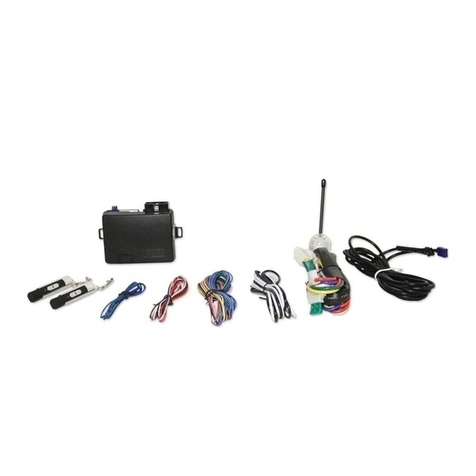
COMPONENTS
1- Main Control Module
2- Four Button Remote
Transmitters
1- 6 Pin Ignition Harness
1- 5 Pin Harness
1- 10 Pin Mini Out ut Harness
1- 9 Pin Mini In ut Harness
1- 2 Pin Valet Switch
1- 2 Pin Led Light Harness
1- 4 Pin Antenna Harness
1- 3 Pin Door Lock Harness
1- 4 Pin Shock Sensor Harness
1- Six Tone Mini Siren
1- Hood Switch
1- Hood and Window Decal
1- Installation Manual
1- Owners Manual
Read the o eration manual for o erating and rogramming routine.
Do not install any com onent near the brake, gas edal or steering
linkage.
Most vehicles have an SRS air bag system. Use extreme care and
do not robe any wires of the SRS system. These wires will almost
always be located inside a bright yellow tube located near the
steering wheel column.
Check behind anels before drilling any holes. Ensure that no wiring
harness or other com onents are located behind the anels that
would otherwise be damaged.
Do not use conventional crim lock or bullet connectors on any
wiring.
Do not disconnect the battery if the vehicle has an anti-theft radio
or is equi ed with an airbag. Doing so may cause a warning light
to be dis layed and the radio to sto functioning.
Do not leave the interior or exterior lights on for an extended
eriod of time. Remove the dome light fuse from the vehicles fuse
box.
Do not mount the control module until all connections have been
made and the unit is rogrammed and tested.
Finally lace the warning sticker under the hood when the installation
is com leted.

. .
7
INSTALLATION DIAGRAM
Violet Wire
Loop:
Selector for
automatic or
manual
transmission.

. .
8
WIRING HARNESSES
Keep all wiring away from moving engine parts, exhaust pipes and high-
tension cable. Tape wires that pass through holes on the firewall to prevent
fraying. Watch out for sharp edges that may damage wires and cause
short circuits.
CAUTION: Do not connect the wire harness to the control
module until all wirin to vehicle is complete.
1. ual pulse door unlock output
2.Factory disarm signal output
3.Start Status (shock sensor by-pass control) Output
VIOLET

. .
9
WIRING CONNECTIONS
H1: 6-PIN HEAVY GAUGE WIRING CONNECTIONS:
Remember that the system is designed to duplicate the same functions
of the ignition key switch! Since this installation will require analysis of
the ignition switch functions, we recommend making the H1 harness
connections directly to the ignition switch wires.
H1/1 VIOLET Wire(Starter Cran Output)
onnect the VIOLET wire to the starter crank wire at the ignition switch
harness. This wire show +12 volts when the ignition switch is turned
to the start or cran position only. This wire will test 0 volts in all
other ignition switch positions
H1/2 and H1/3 RED Wires (2)-(+12V Power Input)
Remove the (2) two 20A fuses prior to connecting these wires and do
not replace them until the satellite harness has been plugged into the
control module. These two wires are the source of current for all the
circuits the relay satellite will energize. They must be connected to a high
current source. Since the factory supplies (+) 12V to the key switch,
it is recommended you make your connections there.
Note: If the factory supplies two separate (+) 12V feeds to the ignition
switch, connect (1) RED wire of the satellite to each feed at the switch.
H1/4 YELLOW Wire (Ignition 1 Output)
onnect the YELLOW wire to the ignition 1 wire from the ignition switch.
The ignition wire should receive "12 volts" when the ignition key is in
the "on" and "start" or cran positions. When the ignition is turned
"off", the ignition wire should receive "0" voltage. The YELLOW wire
must be connected.
H1/5 PINK Wire (Ignition 2 Output)
Some vehicles have 2 ignition wires that must be connected. Attach the
PINK wire to the ignition 2 wire from the ignition switch. The ignition
wire should receive "+12 volts" when the ignition key is in the "on" or
run and "start" or cran positions. When the ignition is turned to
the"off" position this wire will show "0" voltage. If the PINK wire is
not used, cap or tape the end of the wire.
On some GM vehicles, the second ignition wire may also show voltage
in Off of Accessory positions. There will be 0 voltage when the key
is removed (Lock position).

. .
10
H1/6 BROWN Wire Accessory Output (Heater /AC Output)
Connect the BROWN wire to the Accessory/Heater-Blower wire in the
vehicle that powers the Heater/AC system. The Accessory/Heater-Blower
wire will show + 12 volts when the ignition switch is turned to the
accessory(some vehicles) on or run positions and will show
0 volts when the key is turned to the off and start or crank
positions. On some vehicles there will often be more than one
Accessory/Heater-Blower wire in the ignition harness. The correct
Accessory/Heater-Blower wire will power the vehicles Heater/AC system.
Note: Some vehicle may have separate wires for the blower motor and
the air conditioning compressor such as Ford products. In such cases
it will be necessary to add a relay to power the second Accessory/Heater-
Blower wire if your vehicle does not have a Ignition 2 wire use the
Ignition 2 Output (H1/5 PINK) wire from the remote starter to power
up the second Accessory/Heater-Blower wire.
H2:5 PIN WIRE HARNESS:
H2/1 RED / WHITE Wire (Parking Light Relay Input)
The RED/WHITE wire is the input for the parking light relay. This
wire will determine the output polarity of the parking light relay.
If your vehicle requires +12volts to power the parking light circuit
you will not need to connect this wire. This wire is already connected
to the +12 volt constant RED wire in the same harness.
If your vehicles parking light circuit operates on a switched (-)
negative ground then cut the RED/WHITE wire from the RED
wire and attach it directly to a ground source. Note: Make sure
to tape the RED wire at the cut location.
H2/2 WHITE Wire (Parking Light Relay Output)
Connect the WHITE wire to the wire that powers the parking light circuit
on the vehicle. The WHITE parking light wire is rated at 10amps max
and should not exceed this current. If your vehicles parking light system
requires more than 10amps you must add a relay to power the parking
light system
H2/3 BLACK Wire (System Ground)
This is the main ground connection of the control module. Make this
connection to a solid section of the vehicles frame ground.
WIRING CONNECTIONS

. .
11
WIRING CONNECTIONS
H2/4 BROWN Wire (Siren Output)(Factory De ault setting)
The BROWN wire will provide a (+) positive output for the optional
siren. Also programmable for horn output (relay required).
H2/5 RED Wire (System +12volt Constant Power)
Connect the RED wire to a constant +12 volt source.
The RED wire supplies power to the system. Connect this wire to a
constant +12 volt source.
H3: BLACK 4-PIN CONNECTOR,
TWO-WAY TRANCEIVER/ANTENNA MODULE
The two-way transceiver antenna mounts on the location above the belt
line (dashboard) of the vehicle for best reception. We suggest you mount
it on the lower left or upper left-hand side of windshield. Warning! Do not
mount in such a manner that it obstructs the drivers view.
Remove the protective tape backing.
Carefully align the two-way transceiver antenna and apply to the
windshield.
Route the black connector wire behind the trim and connect to the
two-way transceiver antenna.
Connect the other end to the control module.
Special considerations must be made for windshield glass as some newer
vehicles utilize a metallic shielded window glass that will inhibit or restrict
RF reception. In these vehicles, route the two way transceiver antenna
module away from metallic shielded window glass as far as possible.
H5 9-PIN BLACK WIRING HARNESS:
This wire provides an instant shutdown for the remote start, whenever it
is grounded. Connect the wire to the hood pin
switch previously installed. This wire must
be routed though a grommet in the
firewall and connected to the hood
pin switch. If the pin switch is to
be used with an alarm system,
connect this wire with diode.
H5/1 GREY Wire (-) (Negative Sa ety Shut Down For Hood Switch)

. .
12
WIRING CONNECTIONS
Important! This connection is a safety wire
and must be connected as specified. Failure
to do so may result in personal injury or
property damage. See detail of wiring in
the following diagram. This wire may also
be used if the vehicle brake light circuit
switches ground to the brake lights. An
isolation diode must be used for ground
switched brake light circuits and must be
connected to the output of the brake switch.
H5/2 BROWN/RED Wire (+) (Po itive Safety Shut Down For Brake)
This wire provides an instant shutdown for
the remote start whenever it receives
+12volt . If the brake lights switch in the
vehicle switches +12 volt to the brake light circuit
connect this wire to the output side of the brake
switch. This will allow the remote start to shut
down if an attempt is made to operate the vehicle without
the key while running under the control of the remote start. In most vehicles
in order to shift gear the brake pedal must be depressed. The brake input will
in turn cause the remote start unit to shut off. (See diagram.)
Manual Tran mi ion: When installing on a manual transmission you also
need to connect the BROWN / RED wire into the handbrake switch. An
isolation diode must be used for handbrake switched light circuits and brake
light circuit. Most handbrake wires will show +12V at rest when the ignition
is on and ground when you set the handbrake. however if the handbrake
wire shows 0V while the handbrake is at rest you will need to add a relay
as illustrated in the diagram below.
H5/1 GREY Wire (-) (Negative Safety Shut Down For Hood Switch)

. .
13
WIRING CONNECTIONS
H5/3 Thin BLACK Wire ( Remote Start Enable or Ne tral Safety Inp t)
When the Thin BLACK wire is grounded, the remote start unit is operable.
When this wire is open from ground, the remote starter is disabled.
1. An optional toggle switch can be added on to this wire to temporally
disable the remote starter. This feature is useful if the vehicle is being
serviced or stored in an enclosed area.
2. This wire can also be connected to the neutral safety switch wire in the
vehicle.
IMPORTANT NOTE: Directly connect the Thin BLACK wire to gro nd
when not being sed. The remote starter will not work if this wire
is not gro nded.
H5/4 BLUE / WHITE
Wire
(-) Instant Trigger or Major trigger
Inp t (Zone 2)
This wire is the (-) negative ground trigger input wire for hood/trun pin
switches.
H5/5 GREY/BLACK
Wire
(Negative Diesel Wait to Start Inp t)
The GREY/BLACK wire is a (-) negative input for diesel vehicles only.
This wire will attach directly to the wait to start bulb on the dashboard,
or on some vehicles the ECM module. You must locate and test the wire
that will provide a ground signal when the wait to start light is on. The
correct wire will provide a ground signal when the bulb is on and +12volt
positive when the bulb is out. There are some vehicles that will have the
opposite configuration and you will need to wire a relay to convert the
polarity. (See diagram example below) You must program the control
module for diesel mode. (See programming Start Feat re #1.)
H5/6 GREEN
Wire
(Negative Door Inp t) (Zone 3)
The GREEN wire is the (-) negative ground trigger input for negative
style door circuits. This green wire will attach to the wire in the vehicle
that provides a ground when any of the doors are opened. The same wire
in the vehicle will provide +12volts positive or 0 voltage when the doors
are closed.

. .
14
WIRING CONNECTIONS
H5/7 VIOLET
Wire
(Positive Door Input) ( one 3)
The VIOLET wire is the positive trigger input for +12volt positive style
door circuits. The VIOLET wire will attach to the wire in the vehicle that
provides +12volt positive when the door is opened. The same wire in
the vehicle will provide 0 voltage or negative ground when the doors are
closed. This type of door circuit is most common with Ford vehicles.
H5/8 WHITE/BLACK
Wire
(Instant Start and Stop Input)
The WHITE/BLACK wire will activate and deactivate the remote starter
when it sees a momentary (-) negative ground.
This wire is used for testing purposes and to activate the remote starter
from another source.
H5/9 VIOLET / WHITE Wire (Tach. Input or Oil Sensor Connection)
(Tach Input Connection)
Note: No connection of this wire is required, if you are using the voltage
checking type mode. This input provides the remote start system with
information about the engine s revolutions per minute (RPM). It can be
connected to the negative side of the coil in vehicle with conventional
coils. To test for a tachometer wire, a multi-meter capable of testing AC
voltage must be used. The tach wire will show between 1V and 6V AC
at idle, and will increase as the engine RPM increases. In multi-coil ignition
systems, the control module can learn individual coil wires.
IMPORTANT! Do not test for tach wires with a test light or logic probe.
How to find a tach wire with your multi-meter
1. Set the ACV or AC voltage (12V or 20V is fine.)
2. Attach the (-) probe of the meter to chassis ground.
3. Start and run the vehicle.
4. Probe the wire you suspect of being the tach wire with the red probe
of the meter.
5. If this is the correct wire the meter will read between 1V and 6V.
IMPORTANT NOTE: You must program the Tach Signal before
trying to remote start.
Oil Sensor Signal Connection
Locate the wire connected to the oil sensor on the dashboard or to the
generator in the engine compartment.

. .
15
Negative Oil Sensor Connections: +12volts to +14volts will show
on the multimeter when the ignition switch is turned to the ON position
in the key cylinder and +2volts to + 3volts when the motor is running.
Positive Oil Sensor Connections: +2volts to + 3volts will show on
the multimeter when the ignition switch is turned to the on position in
the key cylinder and +12volts to +14volts when the motor is running.
IMPORTANT NOT : You must program for oil sensing type before
trying to remote start. (See programming start feature #2.)
WIRING CONN CTIONS
H6: 3-PIN DOOR LOCK CONN CTOR:
BLUE wire
GREEN wire

. .
16
WIRING CONNECTIONS
VACUUM OPERATED DOOR
LOCKING SYSTEM:
TYPICAL OF MERCEDES BENZ
AND AUDI.
Locate the wire under the driver's
kick panel. Use the voltmeter
connecting to ground, verify that
you have the correct wire with the
doors unlocked, the voltmeter will
receive "12 volts". Lock the doors
and the voltmeter will read " volt".
Move the alligator clip to +12V and
the voltmeter will receive "+12 volts". Cut this wire and make your
connections. Be sure to program the door lock timer for 3.5 seconds.

. .
17
WIRING CONNECTIONS
H7: 4 PIN ORANGE CONNECTOR FOR 2 STAGE SHOCK SENSOR
(ZONE 1 / 4)
H8: 10-PIN WHITE WIRING HARNESS:
H8/1 BLUE / BLACK W re (Ign t on 3 Output)
This wire provides a 200mA (-) negat ve ground output that becomes
active 4 seconds before the remote start unit initializes, and remains
grounded while running.
Ign t on 3 output:
Some newer vehicles use a
third ignition wire which is
required to start and keep
the vehicle s engine running.
If this is the case, wire an
IGN 3 relay (not supplied) as
shown below: Do not connect
any vehicle circuits together, they
are isolated for a resaon.
H8/2 BLACK/VIOLET
W re
(T mer Control Channel 6 Programmable Output)
The BLACK/VIOLET wire provides a 200mA (-) negat ve programmable
ground output for a variety of optional devices. The output on the
BLACK/VIOLET wire is programmable from 1 to 120 seconds. (See
programm ng nstruct ons.) This wire can be used to open a sunroof,
or any power device you choose to control. The BLACK/VIOLET wire
must be wired to a relay when powering any devices. Note: factory
default sett ng s a 1 second momentary ground. (See operat ng
nstruct ons.)
To activate this feature press the transmitters and
buttons at the
same time.

. .
18
WIRING CONNECTIONS
H8/3 BROWN/BLACK
Wire
(Horn or Factory Rearm O tp t)
The BROWN/BLACK wire provides a 200mA (-) negative output for
hooking up to the vehicles horn relay activation wire. This wire can also
be programmed to use as a factory rearm wire. hen programmed for
factory rearm a (-) negative pulse is provided after the remote starter
times out or is shut down with the transmitter. Note: factory defa lt
setting is for horn o tp t. (See programming Alarm Feat re #3.)
Factory Sec rity Rearm Signal O tp t ( H8/3 BROWN/BLACK
Wire)
This (-) negative output is programmable. If programmed for rearming
a factory installed security system. This wire will supply a pulse whenever
the remote start times out or is shut dowm using the transmitter and
remote door locking.
H8/4 BLACK/WHITE
Wire
(Dome Light S pervision O tp t)
The BLACK/WHITE wire provides a 200mA (-) negative output for 30
seconds when the doors are unlocked using the transmitter. The
BLACK/WHITE wire will also flash the dome light circuit for the same
duration as the siren when violated. Note: If not attaching the
BLACK/WHITE wire directly to the BCM (Body control mod le) a
relay m st be sed to power the dome light circ it.
H8/5 BLACK/RED
Wire
(Timer Control Channel 5 Programmable O tp t)
The BLACK/RED wire provides a 200mA (-) negative programmable
ground output for a variety of optional devices. The output on the
BLACK/VIOLET wire is programmable from 1 to 120 seconds. (See
programming instr ctions). This wire can be used to open a sunroof,
or any power device you choose to control. The BLACK/RED wire must
be wired to a relay when powering any devices.
Note: factory defa lt setting is a 1 second momentary gro nd.
(See programming instr ctions.)
To activate this feature press the transmitters and b ttons at the
same time.

. .
19
WIRING CONNECTIONS
H8/6 VIOLET/BLACK
Wire
(Timer Control Channel / Key Sensor Output)
The VIOLET/BLACK wire provides a 200mA (-) negative programmable
ground output for a variety of optional devices. The output on the
BLACK/VIOLET wire is programmable from 1 to 120 seconds. (See
programming instructions). This wire can be used to open a sunroof,
or any power device you choose to control. The VIOLET/BLACK wire
must be wired to a relay when powering any devices. Note: factory
default setting is a 1 second momentary ground. (See programming
instructions for operation of this output)
Note: this wire can also be programmed as a second start crank
output. (See programming instructions). Some vehicles re uire a
second starter wire to be energized, or on certain GM vehicles what is
known as the bulb check wire must receive a ground signal while the
starter is cranking. When using this wire as a second start wire (Most
Nissan vehicles) a relay must be used to energize this circuit. To activate
this featyre, press the transmitters and buttons at the same time.
H8/7 RED/WHITE
Wire
(Channel 3 Trunk Output)
The RED/WHITE wire will provide a 1 second 200mA (-) negative
ground pulse output by activating channel 3 on the transmitter for 2
seconds. This feature will allow a trunk release or other optional devises
to activate by remote transmitter. . Note: If not attaching the
RED/WHITE wire directly to the BCM (Body control module) a
relay must be used to power the trunk or device being energized.
H8/8 LT.GREEN / BLACK
Wire
( Step 2 Door Unlock / Factory Disarm
Shock Sensor Bypass)
Dual Pulse Door Unlock Output
The dual pulse door unlock feature will work for most of the fully electronic
door lock circuits. When wired for this feature, pressing the disarm (or
unlock) button one time will disarm the alarm and unlock the driver's
door only. If you press disarm (or the unlock) button two times within
3 seconds, the alarm will disarm and all the doors will unlock. This is a
(-) negative output.

. .
20
WIRING CONNECTIONS
Factory Security Disarm Signal Output Factory Default
This wire is designed to disarm a factory installed security system. This
wire sends a ( ) negative 1 seconds pulse upon a remote start and
remote door unlocking. Some factory systems must be disarmed to allow
remote starting. In most cases, this wire may be connected directly to
the factory alarm disarm wire. The correct wire will show negative ground
when the key is used to unlock the doors or trunk. This wire is usually
found in the kick panel area in the wiring harness coming into the car
body from the door.
Start Status (Shock Sensor By Pass Control) Output
This wire is designed to by pass a shock sensor module. This wire will
supply an output at all times the remote start is operating plus an
additional 3 seconds after the remote start unit is turned off.
H8/9 ORANGE/WHITE
Wire
(Ground Output When Disarmed)
The ORANGE/WHITE wire provides a 200mA ( ) negative output when
the security system is disarmed. This output can be used for activating
optional devises such as memory positions for power seats. Note: If not
attaching the ORANGE/WHITE wire directly to the BCM (Body
control module) a relay must be used to power the device being
energized.
Other Alert Remote Starter manuals
Popular Remote Starter manuals by other brands

NOCO Genius
NOCO Genius BOOST X GBX45 User guide & warranty

Audiovox
Audiovox AA-RS40CS Install manual

CrimeStopper
CrimeStopper CS-865RKE II Series Installation & operating instructions

MATSONIC
MATSONIC ra3800 Operator's manual

Westfalia
Westfalia Jumper instruction manual

Smartech
Smartech GSK-10000 user guide

Audiovox
Audiovox Prestige APS-45 installation instructions

Clifford
Clifford Responder LE 3.3X owner's guide

Scytek electronic
Scytek electronic A777 product manual

Essex Electronics
Essex Electronics Encoded Keyless Entry Installation instructions manual

Omron
Omron G8D-584M-B1 manual

GYS
GYS GYSPACK PRO 800 operating manual