Alfa Network Thor Instruction sheet

Operator Manual –Thor
EN
INSTALLATION
1
First Start Manual
ORIGINAL INSTRUCTION
Code:
Year:
2019
Rev.:
02
www.alfadispenser.com
Thor

Operator Manual –Thor
2
INSTALLATION
EN
3. INSTALLATION
3.1. CHOOSING THE ROOM
The machine must be installed in a manned room, complying with the requirements in chapter 1.
DO NOT INSTALL THE MACHINE OUTDOORS OR ANYWHERE EXPOSED TO WEATHER.
THE EQUIPMENT IS NOT SUITABLE FOR INSTALLATION IN AREAS WHERE WATER SPRAY COULD BE
USED.
ONLY INSTALL ON SMOOTH, FLAT AND STEADY FLOOR, ABLE TO SUSTAIN THE MACHINE FULL-LOAD
WEIGHT.
THE MACHINE MUST BE POSITIONED ON A HORIZONTAL SURFACE (FLOORING WITH A GRADE BELOW
2%)
INSTALLATION ON INTERMEDIATE FLOOR IS ALLOWED ONLY IF THE REQUIRED LOAD BEARING
CAPACITY IS VERIFIED (>1000KG/SQ.M).
INSTALL THE MACHINE AT 5-10 CM FROM THE WALLS, AND ENSURE THAT THE ROOM EASILY ALLOWS
YOU TO EASILY OPEN THE SERVICE COMPARTMENTS AND THAT THE CIRCUIT BREAKER CAN BE EASILY
ACCESSED.
3.2. PRODUCT LABEL AND ELECTRICAL CONNECTION
Make sure that the system meets the electrical
requirements specified on the machine nameplate, then
connect the power cable to the socket.
Model: machine model
Type: machine type
Vnom: power supply voltage
Hz: mains frequency
Imax: absorbed current*
SN: serial number
Made in Italy: year of manufacture
Fuse Rate: fuse value
The machine is equipped with a detachable power cable
for connection to the mains.
Connect the machine to the mains using exclusively the
cable supplied.
Always make sure that the voltage output from the mains is
compatible with the nameplate specifications.
* maximum absorbed current in case of use of Thor at full
load and of AUX sockets (see chap. 1 –ELECTRICAL
CONTROL PANEL) with load of 200W.
USE ONLY LISTED DETACHABLE POWER SUPPLY CABLES NOT EXCEEDING 4.6 M. LENGTH,
TYPE SVT OR SJT, 3X18 AWG 10 A, WITH GROUND CABLE.
To ensure the correct machine operation and the highest safety level, it is essential that the machine is connected to
ground. Make sure that the system is connected to a power supply with an efficient ground.
WARNING: ONLY CONNECT THE MACHINE TO ELECTRIC SYSTEMS PROVIDED WITH
GROUND CIRCUIT CONNECTION COMPLIANT WITH THE NATIONAL STANDARDS.

Operator Manual –Thor
EN
INSTALLATION
3
3.3. COMMISSIONING - INSTALLATION
3.3.1. REMOVING THE MECHANICAL AND PARKING RETAINERS
The semi-finished product carriage is secured to
the machine by means of two small brackets.
Loosen the screws and the brackets (1) with a 4
mm Allen key.
Once the machine is in the correct position, it must be
stabilized on the adjustable supporting feet, acting as
follows for each one of the 2 feet:
Work on the nut/recess located at the base of the
screw (1) with a 10mm wrench to lower the foot
until the nearby wheel is completely lifted. As an
alternative, tighten an M12 nut fully home on the
insert (2) and work on it to lift or lower the foot
using a 19mm wrench.
Use a spirit level to correct the height of the 2 feet
until obtaining a good alignment.
Use an M12 nut to lock the foot;
3.3.2. UNLOCKING TURNING TABLE
The turning table is fixed to the cabinet by 4 columns that
prevent rotation during transport. Unlock the turning table
as follows:
Remove the upper side panels by loosening the
M6 TCEI screw (1) with a 5 mm Allen key and the
M5 TCEI screw (2) inside the machine with a 4 mm
Allen key. To reach the internal screw access from
the rear panel. The side panel can then be
removed by sliding it towards the back of the
machine.

Operator Manual –Thor
4
INSTALLATION
EN
Remove the 4 columns (3), two on each side of the
turning table securing the turning table (4) to the
fixed base (5) by loosening the corresponding M5
TCEI screws on top of each column and the M6
TCEI screws under each column.
3.3.3. SEMI-FINISHED PRODUCT CARRIAGE EXTRACTION
To extract the base carriage from the cabinet the safety
lock has to be released:
Press button (1) and extract the cabinet by acting
on handle (2).
3.3.4. CONTROL PC INSTALLATION
Connect the PC to a suitable power socket. If AUX sockets
available on the Alfa tinting machine are used, check the
electrical characteristics on the data plate.
Then connect the PC Ethernet plug to the machine
Ethernet socket (or to LTE modem, if any) using the cable
supplied with the machine. For the first setup of the
machine or to retrieve the DHCP IP address assigned by
the network to a machine connected to the LAN, it is
necessary to connect to the “0.100” (1) port of the
machine.
If an LTE modem router is used, refer to the next
paragraph.
Connect the accessories required, such as monitor,
mouse, keyboard, and printer if necessary.
DISCLAIMER
Alfa machines are set for local network communication with third party devices and for access to services via internet
(alfa-cloud, alfa-service in VPN, etc.) using Ethernet or wireless interfaces.
These systems are NOT designed to be directly used online, as they do not ensure the necessary cyber security
protection.
Direct exposure of network interfaces to the internet network without a firewall or similar protection system
poses a cyber security risk, that must be avoided with a suitable configuration at the time of installation and
for which Alfa srl is not responsible.

Operator Manual –Thor
EN
INSTALLATION
5
3.3.5. CONTROL SOFTWARE
To control the dispenser, Alfa makes the web-based
interface called AlfaTint available to all its customers.
In case you wish to apply your own software, Alfa provides
a series of calls (API Rest) allowing interfacing the
machine with any third-party software.
For more details on the API Rest, please refer to the
technical manual or contact Alfa Service Department.
In the following, we will refer to AlfaTint interface
commands.
3.3.6. LTE ROUTER MODEM INSTALLATION (OPTIONAL)
LTE modems supplied by Alfa are always configured to
provide router-machine communication at the address
192.168.0.100.
In case the router is used, it will be necessary to start VPN
connection by using the specially provided certificate and
to connect to the router IP by setting the last digits of the IP
address to 100 (see technical manual for more detailed
information).
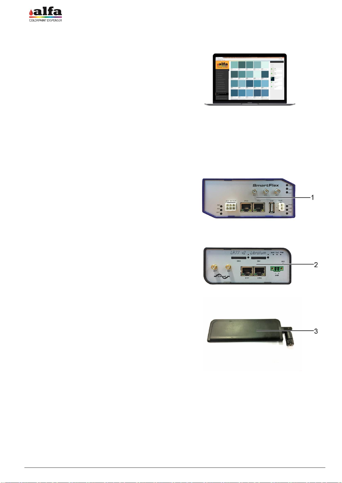
Different LTE Routers may be supplied, depending of the
destination market of the machine.
With reference to the figure on the side, the upper model
(1) is suitable for North American markets (Mexico, USA,
Canada), whereas the lower model (2) can be used
elsewhere in the world. Further models can be used in
specific areas where special type-approval requirements
are necessary (e.g. Australia).
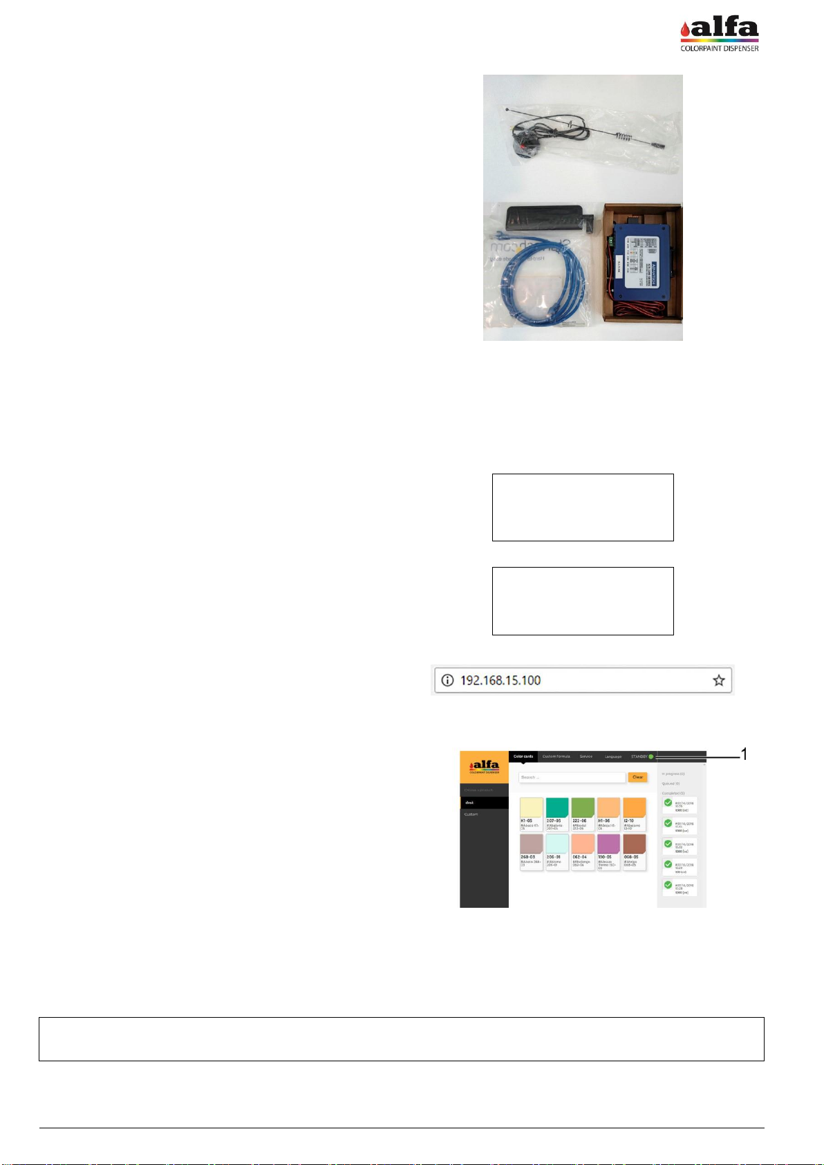
- Connect the machine Ethernet 0.100 plug to one of the
two Router Ethernet sockets and the PC Ethernet plug
to the other Router Ethernet socket;
- Connect the power cable present inside the router box
between modem PWR connector and 24Vdc socket
available in the internal power supply unit. As an
alternative, it is possible to use the power supply unit
included in the package, to be directly connected to an
external mains socket.
- Screw the antenna supplied (3) to ANT threaded
connector;
- Insert a data SIM into SIM1 slot, taking care to
previously check that no PIN is enabled (before
inserting the SIM into the router, insert the SIM into a
telephone and disable the PIN if necessary).
NOTE: In some types of modem, SIM1 slot can be
located in the rear part of the modem.

Operator Manual –Thor
6
INSTALLATION
EN
Check that the accessory kit includes:
Modem
Network cable
No. 2 antennae
If necessary the antenna equipped with cable and magnet
can be used.
3.4. SWITCH-ON AND INITIALISATION
Connect a PC to the machine Ethernet “0.100” socket using the supplied Ethernet cable, then proceed as described.
Update the PC network configuration so that the IP
address is within the same subnet as that of the
machine (see the adjacent example).
The machine default IP address is 192.168.0.100.
For more information on how to modify your PC's
IP address, contact your IT administrator.
Turn on the machine by turning the on switch to its
“I” position.
MACHINE:
IP: 192.168.0.100
NETMASK: 255.255.255.0
PC:
IP: 192.168.0.XXX
NETMASK: 255.255.255.0
xxx = free subnet address
Open the Alfa TINT control interface on the
Internet browser (preferably Chrome or Mozilla
Firefox) and enter the address indicated in the
figure.
When the interface displays the window shown in
the figure, the machine is ready to be
commissioned and used.
If the window is not displayed, check the Ethernet
connection.
On top right you can always see the machine (1) status.
Upon switch-on, the machine is in ALERT status (red
status indicator).
To use the machine it is necessary to perform a RESET.
When the operation is completed, check that the STAND-
BY status is displayed.
If the machine shows alarm or error warnings, check type of alarm and take the required steps to restore proper
operation (see Chapter 8 - Trouble Shooting).
If machine does not switch on, check that power voltage is correct and fuse is not blown.
For further details on malfunction issues, please refer to Chapter 8 "Trouble Shooting".
WARNING: if you are unable to communicate with the machine via the web browser, turn off the machine
and contact the manufacturer's technical support service.

Operator Manual –Thor
EN
INSTALLATION
7
3.5. SWITCH-OFF
In order to switch off the machine, turn the main switch to its “O” position and disconnect the power cable from the
socket.
WARNING: in order to disconnect the machine, the operator must not rely exclusively upon the power switch,
but must also unplug the machine power cable.
NOTE: The Thor is provided with an integrated board whose aim, among other things, is to maintain the
internal 12V power supply for the time required to safely shut down the Linux board (approx. 60 seconds).
Any voltage interruptions or dips with a shorter duration do not cause machine switching off by the PC.
3.6. COMMISSIONING - PREPARATION
3.6.1. DYE CANISTER LOADING
Each colorant group is matched to a hardware address.
By convention, colorant order is as shown in figure below.
The canisters are always marked with labels from C1 to
Cn, according to the actual number of present circuits.
The position-colorant association can be viewed by
accessing the special software section.
Such associations can be modified by qualified
TECHNICAL personnel. For further information, refer to the
Software manual.
Upon first installation, the technician must set the proper
tinting system and fill the tanks according to the proper
sequence.
To load the products refer to chapter 5.
WARNING: Do not overfill the tanks.
Then, trigger the circuits and leave them in recirculation
mode for the time needed (see chapter 3 -
RECIRCULATION).
The tinting system loaded on the machine can be changed,
as well as the colorant software indexing. These
operations are reserved to authorised technical staff.
To see or change the positions associated with each
colorant, please refer to machine configuration (ref.
"Software manual").

Operator Manual –Thor
8
INSTALLATION
EN
3.6.2. SEMI-FINISHED PRODUCT LOADING (THOR MASTER VERSION)
The semi-finished products must be loaded in the semi-finished product carriage tanks. Fill as follows:
Extract the semi-finished product (1) carriage.
Remove the covers (2) and fill the tanks with the
product indicated by the software.
The semi-finished product carriage can have different
configurations; the circuit numbers are indicated on the
circuits.
WARNING: Do not overfill the tanks.
Refer to paragraph 5 for the correct filling methods.
3.6.3. MOISTURISING FUNCTION
The autocap, if present, includes the components necessary to keep the nozzles humidified in order to prevent or
reduce the drying of the products at the nozzle ends.
The system is composed of a distilled water tank built inside the autocap, of a resistance and of a level sensor.
Safety function
A level sensor allows detecting when the level of the liquid inside the tank is low and allows the machine to disable
moisturising function until the liquid level is restored. If the level is too low the alarm “TOO LOW WATER LEVEL” will
be displayed by the machine.
Operation parameters
The machine periodically activates the resistance according to factory preset power levels and intervals, as shown in
the table below.
Closed autocap
Open autocap
Power
20W x 0.3 (PWM 30%)
20W x 0.3 (PWM 30%)
Repetition interval
200”
60”
Duration
55”
20”
Parameters can be changed by authorised operators (see technical manual and/or software manual).
When switching on the machine, perform the autocap moisturising as described in chapter 6 –AUTOCAP CLEANING
AND MOISTURISING.
3.6.4. SEMI-FINISHED PRODUCT CIRCUIT OPENING
Under the tanks there are the relevant pumping units
provided with shut-off valves (1). Upon commissioning and
before testing the circuits, check that the valves are open.

Operator Manual –Thor
EN
INSTALLATION
9
3.6.5. CIRCUIT TRIGGERING AND RECIRCULATION
Before using the machine, trigger circuits and leave them in recirculation mode.
Once the circuits are full, it is recommended to perform some purge cycles and leave the machine in stand by mode
for at least 12 hours, a period of time usually sufficient to remove the residual air from the circuits.
3.6.6. SETUP OF CIRCUITS
The machine is now ready to be initialised or for producing the first sample.
Typically, the machines leave the factory with all circuits already characterised and ready to be used with the colorants
of the tinting system specified in the order.
When using dyes that are not yet characterised on a software level, the circuits need to be set up first.
An incorrectly characterized machine can cause significant color production errors. Circuit setup is a procedure
reserved for expert technicians so, if necessary, contact Alfa-authorised Technical Service. Circuit setup execution
modes are described in the Software Manual.
Once the recirculation and setup stages are completed, the machine is ready for dispensing a test sample and
commissioning.
Refer to "How to produce a sample” to perform a test production run.

Operator Manual –Thor
10
HOW TO PRODUCE A COLOUR
EN
4. HOW TO PRODUCE A COLOUR
4.1. MACHINE STATUSES
On top right of the Alfa TINT software interface you can
always see the machine (1) status. Following are the
possible machine statuses:
STANDBY: machine ready, waiting for controls
DISPENSING: dispensing in progress
RESET: reset in progress
ALARM: machine error
DIAGNOSTIC: machine waiting for direct controls
The direct controls are described in the following
paragraphs.
4.2. PRODUCTION OF A COLOUR
Once the system is installed, it is possible to start the production. To produce a colour, follow the instructions provided
in this paragraph.
4.2.1. ADJUSTMENT OF THE STOOL HEIGHT
Adjust the can lifter height so that the distance between the
upper edge of the can to be used and the nozzle is of 2-
3cm.
To modify the height, manually remove the table
top (1) and place it in the appropriate height rail
(2).

Operator Manual –Thor
EN
HOW TO PRODUCE A COLOUR
11
4.2.2. FORMULA SELECTION AND DISPENSING
Formulas concerning different types of product (e.g.:
washable paints for outdoor use / washable paints for
indoor use / quartz /...) can be loaded onto the machine,
each one of them characterised by its own set of original
formulas. The types of products are listed in the column on
the left (1).
Start the control interface Alfa TINT on the browser web
Select the desired product type (1).
The Color cards tab (2) shows a preview of the
available colours (3) and a search bar (4) where to
enter the name or code of the desired colour.
The right column (5) shows the chronology of the last
dispensing cycles.
By selecting a colour, the display will show the
dispensing window (see figure on the side).
In the “Select package size” drop-down menu,
select the desired volume ensuring that it is
consistent with the volume of the can being used.
Then press “Dispense” to start dispensing or “Edit”
to change the formula.
Before starting the dispensing, the machine will
check, by means of a sensor, the actual presence
of the can under the nozzle; if this is not the case,
the display will show the message "Please Insert
Can".
To add a package with different volume, not
present in the drop-down menu, refer to the
software manual (Recipes >> Packages).
During the dispensing, the machine is in
DISPENSING status. When the dispensing is
completed, if there are no errors, the machine will
return in STANDBY mode.
4.2.3. CREATION OF A NEW FORMULA AND CHANGE OF AN EXISTING ONE
If a formula is modified starting from a laboratory one or if a
new formula is created from scratch, this formula is not
saved among the laboratory ones but in dedicated and
different space (e.g. Custom Formulas).
Once an existing formula has been selected, the Edit
control allows accessing the “Custom formula” tab that
contains the formula editing functions.
To edit the recipe starting from the selected formula, enter
the values in cc of the relevant components.
The software offers the possibility to save the formula
without activating it, by means of the “Save” control (1) or
to save the formula and activate it (“Save and Erogate”
control).
The name assigned by default to the modified formula is
“Copy of oldformulaname”. The name can be edited
together with a field for notes that will be saved with the
new formula.

Operator Manual –Thor
12
HOW TO PRODUCE A COLOUR
EN
The display mentioned above can be accessed directly
even from the initial page by selecting the “Custom
formula” tab (2) and can be used to create a new formula.
In this case, the default values of the components will be
all to zero.
All formulas customized by the operator can be viewed
even if they do not have a coloured label, in the “Custom
formulas” product menu (3).
At the end of the dispensing, remove the can and close it carefully, then place it in a mixer unit to mix the paint.
4.3. SERVICE ADVANCED FUNCTIONS
The “Service” tab allows accessing useful functions for the
diagnosis and maintenance operations. Inside this
interface it is possible to send the following direct controls
to the machine:
Purge
Warm Reset (without movements)
Cold Reset
Open Autocap
Close Autocap
Start/Stop Recirculate Circuit (2)
Start/Stop Stirring Circuit (3)
Purge Circuit (4)
Refill
The first three controls (1) are available also with machine
in stand-by mode. The other controls are available only
after switching the machine to “Diagnostic” (5) by pressing
“Diagnostic Mode”.
NOTE: when the stirring command is given for a colorant,
all the colorants are stirred, since the stirring function of the
colorants on Thor is associated with the rotation of the
table.
In diagnostic mode it is also possible to enter the product
quantities added during the circuit refill (see chapter 5 –
MAINTENANCE).
At the end of the service operations, quit the DIAGNOSTIC
mode by starting a Reset.
Cold Reset: performs a complete reset of the machine
by starting all movements to search the photocells.
Warm Reset: quits the Diagnostic mode by performing
only the strictly necessary movements.

Operator Manual –Thor
EN
HOW TO PRODUCE A COLOUR
13
4.4. ACCESS TO THE CONFIGURATION ADVANCED FUNCTIONS
The access to the configuration and diagnostic functions is
allowed only to authorised and qualified TECHNICIANS.
After the authentication, the specialised TECHNICIAN can
access the “Admin” interface (figure on the side), from
which it is possible to manage the configuration advanced
functions, the alarms and the diagnosis.
System administrator can create new users with different
credentials and assign customised passwords. It is
recommended to carefully store the password since it is
not saved anywhere so it cannot be recovered if lost.
If you lose the password, contact system administrator and
request a new temporary password.
For further details consult the Software manual.

Operator Manual –Thor
14
ORDINARY MAINTENANCE AND ADJUSTMENTS
EN
5. ORDINARY MAINTENANCE AND ADJUSTMENTS
5.1. INTRODUCTION
The following paragraphs describe the circuit top-up operations as well as the instructions for simple adjustments that
can be performed by the operator.
Namely:
Colorant and master tanks top-up
Please refer to Chapter 6 for lubrication and cleaning of the machine.
THE OPERATIONS DESCRIBED IN THIS CHAPTER MAY REQUIRE ACCESS TO DANGEROUS SERVICE
AREAS.
ACCESS TO SERVICE AREA IS RESERVED TO TRAINED AND AUTHORISED STAFF (MAINTENANCE
OPERATOR, SEE PARA. 0. –USERS AND ACCESS LEVELS).
5.2. TANK AND CANISTER TOP-UP
When the machine indicates that the product reserve level has been reached, it is necessary to top up the relevant
canister or tank and then record the top-up operation. In order to perform this operation, proceed as follows:
Colorant group canisters:
Top-up using only the canister in the front part of the
machine.
To top-up colorant proceed as follows:
Open AlfaTint “Service” tab and press REFILL button
of the circuit to be topped-up.
Once the table has completed rotation (if necessary)
the circuit will be in the front position and will be ready
for top-up.
Remove the canister lid.
Fill the canister with the appropriate pigment up to the
indicated maximum level (MAX LEVEL).
NOTE: The cross element can be used to support a
container when you leave it to drain. Do not overfill beyond
the recommended level.
Base and semi-finished product tanks:
To top-up semi-finished product circuits, if any, proceed as
follows:
Extract the base/semi-finished product carriage from
the Thor cabinet.
Remove the cover of the tank/tanks to be topped up.
Top up the circuits using the suitable product. Do not
overfill beyond the level indicated by the end of the
stirring blade (MAX LEVEL).
At the end of the top-up operations, close the lids of the
filled circuits and refit the carriage inside the cabinet, then
record the just carried out operation in the software (see
next paragraph).

Operator Manual –Thor
EN
ORDINARY MAINTENANCE AND ADJUSTMENTS
15
5.3. RECORDING THE OPERATION
After each top-up operation it is necessary to record in the software the product added quantity:
Access the “Service” section and then “Diagnostic
Mode”;
In the “Add [cc]” field enter the volume in cc of the
product supplied in the circuit, then press “+”.
Repeat this operation for each topped-up circuit.
Perform a reset to quit the DIAGNOSTIC mode.
5.4. MINIMUM AND RESERVE LEVEL
For each circuit it is possible to define a reserve level (that
can be checked by means of the hardware sensor) and a
minimum level (that can be checked via software).
If the product volume is lower than the reserve level (1)
detected by the sensor, the system shows an alarm.
If the volume is lower than the minimum level (2)
calculated by the software, the system disables the circuit
and does not supply that product until the circuit is topped-
up.
Every time a dispensing control is sent, the software
calculates if the volume of each product in the machine is
sufficient to perform the formula so that the residual
volume is not lower than the minimum set one. In case
even only one of the components of the formula is not
sufficient, the system requires the operator to select
another formula.
5.5. ADJUSTING MINIMUM LEVELS
Thor is not provided with minimum level sensors. Levels are only software controlled.
5.6. PRODUCT DISPOSAL
During the maintenance or repair interventions it may be necessary to empty canisters and tanks from the paints
contained in the circuits.
Colorants and base must be disposed of in suitable collector tanks to be treated and disposed of in a suitable way.
It is forbidden to release the products in the environment or in the public sewers.
Table of contents
Popular Dispenser manuals by other brands

Tork
Tork Xpressnap N4 System Loading Instructions

Perrin & Rowe
Perrin & Rowe Country 6695 Installation & user guide

Franke
Franke XINX625 Installation and operating instructions

Curtis
Curtis TCN Instructions and parts list

Cornelius
Cornelius Brewed Iced Tea Installation & service manual

ECO PRODUCTS
ECO PRODUCTS Cutlerease Refill instructions