DEMA 665 Series User manual

www.demaeng.com
1-800-325-3362
I-1091 Page 1 of 8
Rev. C-40014 08/08/14
Overview
The Extreme 4 makes users more efficient, filling bottles and buckets with ease and quickness. Some of
the great design features include:
A single dial for 8 different dilution points
Multi-point locking system for Extreme security
Integrated ASSE approved backflow prevention
Large sight window to identify product and level
Branding panels to meet the ‘look n’ feel’ need
One-handed bottle and optional remote bucket
fill
Warnings
All installations must conform to
local plumbing codes and use
approved backflow prevention
devices. A pressure indicating tee is
to be installed with existing faucets
according to local plumbing codes in the state of
Wisconsin and any other state that requires the use
of a pressure indicating tee
ALWAYS WEAR PROTECTIVE
CLOTHING AND EYEWEAR
WHEN WORKING WITH
CHEMICAL PRODUCTS
Instruction Sheet Contents Operational Requirements
Category Page Water Supply Requirements
Package Contents / Required Tools 1Minimum Maximum
Operational Requirements 1 Water Pressure 20 psi (1.38 bar) 125 psi (8.62 bar)**
Overall Dimensions 2 Water Temperature - 150ºF (65.5ºC)
Installation / Preparation 2-3
Operation 4 ** Recommended water pressure is between 20 psi (1.38 bar)
and 70 psi. (5.52 bar). If pressure exceeds 70 psi, it is
recommended that a water pressure regulator is used.
Metering Tip Charts 5
Troubleshooting 6
Parts List 7
Warranty Information 8
Box Contains
Metering tip
kit Mounting
hardware, template
& key set
665 series
dispenser Instruction sheet
4 SafeLink cap assemblies OR
Bulk tubing, 4 ceramic weights
and foot valves
Suggested Tools
Hammer Phillips
screwdriver
Drill w/ 3/16”
& 9/32” bits Tape measure
Pencil Level
665 Series Dispenser

www.demaeng.com
1-800-325-3362
I-1091 Page 2 of 8
Rev. C-40014 08/08/14
Overall Dimensions
Installation & Preparation
1. Identify desired location of dispenser. Remove cardboard mounting template from packaging, place
against wall and mark hole locations using the template as a guide.
[For accuracy, use level with template to ensure the dispenser is level on the wall]
2. Install all four supplied anchors into marked hole locations from step 1. Using supplied screws, install
top two screws and hang dispenser from them. Install bottom two screws through dispenser holes
into the anchors.
3. Tighten screws against dispenser to assure a secure fit.
4. Install Drip Tray by sliding into place against
tab in back of drip tray holder.
[Optional: Drill 3/16” hole into drip tray barb and
attach ¼” ID hose (not supplied) for draining
chemical from drip tray (Figure 1)
Figure 1

www.demaeng.com
1-800-325-3362
I-1091 Page 3 of 8
Rev. C-40014 08/08/14
Installation & Preparation Cont’d
Steps 5 through 7 explain how to install metering tips. Metering tips will be installed at the two check
valves located in each compartment. Check valves to bucket fill have a plastic ring, and check valves
for bottle fill do not.
5. To install metering tips, locate the correct
check valve in each compartment. Identify
desired metering tip based on color and dilution
rate on the tip chart for bottle and bucket filling
(Figure 2)
Figure 2
6. Screw metering tip clockwise into exposed
threaded check valve barb
Note: A blank tip can be used to prevent a
product from dispensing at bottle or bucket fill
7. For SafeLink cap and tubing: secure the tubing
over the exposed check valve barb (Figure 3)
For Open container: Measure bulk tubing
needed and cut to length. Install ceramic
weight and foot valve at base of tubing.
Secure top of tubing over the exposed check
valve barb
Note: Softening the tube with hot water will
allow the tube to fit over the barb with ease
Figure 3
8. Position chemical container into each
compartment in desired position and connect
SafeLink cap or install tubing w foot valve and
ceramic weight into open container (Figure 4)
9. Close and lock the cabinet doors
Figure 4
10. Connect the supplied water hose to your water
source and activate the dispenser by selecting
a position on the dial and using either the
bucket or bottle fill activation point (Figure 5)
Figure 5

www.demaeng.com
1-800-325-3362
I-1091 Page 4 of 8
Rev. C-40014 08/08/14
Operation
Chemical Selector Dial (Figure 6)
1. Turn the chemical selector dial to the desired
chemical position, indicated by the directional
arrow
2. Dispense chemical by either activating the
bottle fill lever or bucket fill button (or remote fill
trigger)
3. For rinse water, point the dial straight down at
the water symbol- This is not potable water, do
not drink
Figure 6
Dispenser Activation Points – Bottle Fill (Figure 7)
1. Slide the bottle tube inside the spray bottle and
raise the bottle to engage the u-shaped lever of
the bottle fill assembly
2. To stop filling, lower the bottle and the lever will
disengage
3. Be careful when removing the spray bottle so
as to not splash residual chemical
Figure 7
Dispenser Activation Points – Push Button Bucket Fill (if equipped) (Figure 8)
1. To start the flow of diluted chemical, press
button on unit above selector dial
2. For continuous flow, twist button clockwise
3. To disengage, release button or twist button
counterclockwise
Figure 8
Dispenser Activation Points – Remote Fill (if equipped) (Figure 9)
1. To start the flow of diluted chemical, press
trigger on handle of fill gun
2. For continuous flow, while trigger is pressed,
slide the red lever to one side and release
trigger
3. To disengage, simply press the trigger again
and the red lever will move out of position
Figure 9
www.demaeng.com
1-800-325-3362
I-1091 Page 5 of 8
Rev. C-40014 08/08/14
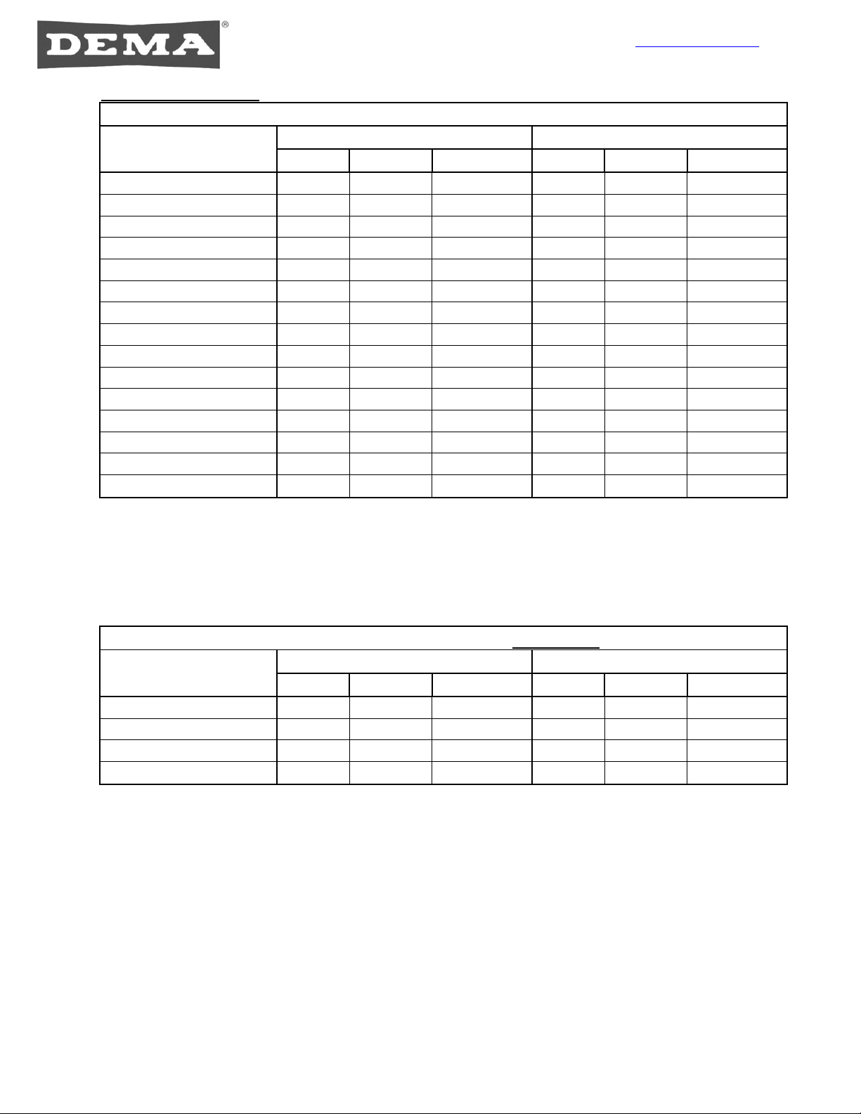
Metering Tip Charts
Table 1: Extreme 4 Metering Tips (Provided)
Metering Tip Color
1 GPM Flow Rate Proportioner 4 GPM Flow Rate Proportioner
Oz./gal ml/L Ratio : 1 Oz./gal ml/L Ratio : 1
Tan 1.25 9.80 102 0.30 2.34 427
Orange 1.70 13.33 75 0.40 3.13 320
Turquoise 2.15 16.67 60 0.50 3.91 256
Royal Blue 2.37 18.52 54 0.56 4.39 228
Charcoal Gray 2.67 20.83 48 0.64 5.00 200
Pink 3.00 23.26 43 0.75 5.88 170
Light Blue 3.90 30.30 33 1.00 7.81 128
Brown 4.55 35.71 28 1.12 8.77 114
Red 5.80 45.45 22 1.50 11.76 85
White 7.00 55.56 18 1.75 13.70 73
Green 7.90 62.50 16 2.00 15.63 64
Blue 9.80 76.92 13 2.50 19.61 51
Yellow 14.80 111.11 9 3.75 39.41 34
Gray 31.60 250.00 4 11.50 90.91 11
No Tip 35.00 277.78 3.6 16.25 125.00 8
INDUCTION RATES BASED ON WATER THIN PRODUCTS (1 cps)
INDUCTION RATES VARY PRODUCT TO PRODUCT. FIELD TESTS ARE RECOMMENDED.
Table 2: Ultra Lean Metering Tips (Not Provided)
Metering Tip Color
1 GPM Flow Rate Proportioner 4 GPM Flow Rate Proportioner
Oz./gal ml/L Ratio : 1 Oz./gal ml/L Ratio : 1
Copper 0.56 4.38 230 0.16 1.25 806
Pumpkin 0.73 5.70 175 0.20 1.56 625
Burgundy 0.90 7.03 143 0.26 2.03 490
Lime 1.28 10.00 100 0.34 2.66 376
INDUCTION RATES BASED ON WATER THIN PRODUCTS (1 cps)
INDUCTION RATES VARY PRODUCT TO PRODUCT. FIELD TESTS ARE RECOMMENDED.

www.demaeng.com
1-800-325-3362
I-1091 Page 6 of 8
Rev. C-40014 08/08/14
Troubleshooting
Symptom Probable Cause Remedy
Proportioner
fails to draw
chemical
properly.
1. Insufficient water supply pressure.
2. Safelink cap has chemical build-up
(if installed).
3. The outlet tubing might be pinched
closed.
4. Chemical metering tip is clogged.
5. Mineral deposits are built up in the
in the proportioner.
1. 20 PSI is the minimum allowable
pressure.
2. Soak in hot water to clean.
3. Straighten out the tubing to remove the
restriction.
4. Remove metering tip from check valve
and replace with new one.
5. Soak proportioner in delimer or off the
shelf product such as CLR to clean
mineral deposits.
“Air Gap”
Proportioner is
dripping or
spraying a mist
(fan pattern) of
water.
1. Mineral deposits are located on Air
Gap nozzle. 1. Soak nozzle and inlet screen in delimer or
off the shelf product such as CLR to clean
and remove mineral deposits.
Water valve is
not shutting off
completely.
1. “Sliding lever” return spring may be
missing on Remote Fill gun.
2. “Sliding lever” is not returning all
the way down due to interference
between the sliding lever and either
the chemical supply and/or outlet
tubing.
3. Bucket fill outlet hose is catching
the bottom edge of the sliding lever
during normal usage.
4. Bottle Fill valve will not shutoff.
1. Remove cover and visually check for
sliding lever return spring. Replace if
missing.
2. Remove cover and visually check for any
tubes rubbing the sliding lever. Routing of
chemical supply and outlet tubing must not
restrict the movement of the sliding lever.
Reroute tubing.
3. Don’t pull the bucket fill outlet hose too
tight from either side otherwise sliding
lever may not return properly.
4. Make sure bottle fill hose is not pressed
against the lever.
Water valve is
leaking. 1. Barbed nut is too loose.
1. Shut water supply off first. Hand-tighten
the barbed nut. Do not over tighten w/tool.
Threaded
connections
are leaking
water.
1. The connection between the
dispenser and water supply line is
too loose or rubber washer is
missing.
2. Backflow prevention devices
and/or proportioners are too loose.
1. Shut water supply off first. Carefully
tighten the female hose coupling on the
dispenser to the inlet water supply line.
Do not over tighten.
2. Tighten loose connection(s) with tools if
necessary. Do not over tighten if using
tools.
Selector valve
is not selecting
the correct
chemical
1. The transmission assembly is
malfunctioning. 1. Make sure the transmission is engaged
with the selector valves. If problem
persists, replace transmission assembly.
Water is
leaking in
between the
two water
valves
1. Plastic fitting connecting the water
valves has lost its seal. 1. Remove the plastic fitting and apply
silicone grease to both O-rings and
reattach to the valves.

www.demaeng.com
1-800-325-3362
I-1091 Page 7 of 8
Rev. C-40014 08/08/14
Parts list
No. Part No. Description Parts Not Shown
1 14-3-3 Cover plate (Button operated) Part No. Description
1 14-3-2
Cover plate (Remote gun
operated) 66-21K Keyset
2 14-2-3 Door – Left side 100-15K-EX4 Metering Tip Kit
3 14-2-4 Door – Right side 10-57-2 Drip Tray
4 10-47 Hinge Pin 100-16V-15 Tubing & Foot Valve Assembly
5 66-339-1 Knob 61-107-2 Ceramic Weight
6 83-53-15 Transmission Assembly 98-40-4 Screw & Anchor Kit
7 63-53-12 Selector Assembly 100-12-38 7/32” Tubing, 15”
8 61-99-4 1 GPM Action Gap Proportioner
8 61-32-AGP 1 GPM Air Gap Proportioner
8 163CHA-NB 2.5 GPM Action Gap Proportioner
8 61-45-4 2.5 GPM Air Gap Proportioner
8 61-22-4 4 GPM Action Gap Proportioner
8 61-126AG-4 4 GPM Air Gap Proportioner
9 16-30 Action Gap Assembly
10 14-5-2 Push Button Valve Assembly
10 14-6-2 Remote Gun Valve Assembly
11 14-6-1 Bottle Fill Valve Assembly
12 98-58-1 Lever Assembly
13 44-3-6FCOS
6’ Black Hose Assembly with
Strainer
14 14-16-1 Check Valve (Threaded)
15 100-12-18 7/32” Tubing, 2”
16 66-500-1 Wye Adapter
17 100-12-19 7/32” Tubing, 5”
18 C38CR4W.00 SafeLink Cap Assembly
19 66-242-1 Bottle Fill Tube – Action Gap
19 66-242-2 Bottle Fill Tube – Air Gap
20 89-30-GAP Bucket Fill Tube – Action Gap
20 85-15-29-6 Bucket Fill Tube – Air Gap
21 98-50-3 Remote Gun Assembly

www.demaeng.com
1-800-325-3362
I-1091 Page 8 of 8
Rev. C-40014 08/08/14
Warranty
Merchandise Returns
No merchandise will be returned for credit without DEMA’s written permission. Please contact
your dealer for warranty issues.
Product Warranty
DEMA’s products are warranted against defective material and workmanship under normal use
and service for one year from the date of manufacture. This limited warranty does not apply to
any products that have a normal life shorter than one year or failure and damage caused by
chemicals, corrosion, physical abuse, or misapplication. Rubber and synthetic rubber parts such
as “O”-rings, diaphragms, PVC tubing, and gaskets are considered expendable and are not
covered under warranty. This warranty is extended only to the original buyer of DEMA products.
If products are altered or repaired without prior approval of DEMA, this warranty is void.
Defective units or parts should be returned to the factory with transportation prepaid. If inspection
shows them to be defective, they will be repaired or replaced without charge, F.O.B. factory.
DEMA assumes no liability for damages. Return merchandise authorization number must be
granted in advance of returned units for repair or replacement (See “Merchandise Returns”
above).
This manual suits for next models
1
Table of contents
Other DEMA Dispenser manuals

DEMA
DEMA Nitro User manual

DEMA
DEMA 607DM-BM User manual

DEMA
DEMA TITAN II Assembly instructions

DEMA
DEMA 302-2 User manual

DEMA
DEMA 301B-SY User manual

DEMA
DEMA 6300 User manual

DEMA
DEMA 693T FOAM STATION II User manual

DEMA
DEMA Extreme 4 User manual

DEMA
DEMA 302-1 User manual

DEMA
DEMA Titan EP Installation guide


