Piusi PW-LAN User manual

M0270 ITEN_00
PW - LAN

M0270 EN 21
EN
1 INDEX
1 INDEX 21
2 CONFORMITY 22
2.1 DECLARATION OF CONFORMITY (94/9/CE, All. VII) 22
3 GENERAL WARNINGS 22
4 SAFETY INSTRUCTIONS 23
4.1 FIRST AID RULES 23
4.2 GENERAL SAFETY RULES 24
4.3 PACKAGING 25
4.4
PACKAGE CONTENTS/PRE-INSPECTION 26
4.5 MACHINE AND MANUFACTURER IDENTIFICATION 26
5 TECHNICAL FEATURES 27
6 OVERVIEW 28
7 INSTALLATION 28
7.1 FIXING TO THE WALL 29
7.2 WIRE CONNECTION 29
7.3 LED & CONNECTORS 31
7.4 GETTING STARTED 32
7.5 NAVIGATION 34
7.6 NETWORK TAB 34
7.7 SYSTEM TAB 35
7.8 RS485 TAB 35
7.9 PROCEDURE TO RESTORE
FACTORY SETTINGS 36
8 DISPOSAL 37

22 M0270 EN
EN
2 CONFORMITY
2.1 DECLARATION OF CONFORMITY (94/9/CE, All. VII)
The Manifacturer:
PIUSI S.p.A
Via Pacinotti 16/A z.i. Rangavino
46029 Suzzara - Mantova - Italia
HEREBY STATES under its own responsibility, that the equipment described
below:
Description: PW-LAN module
Model : PW-LAN
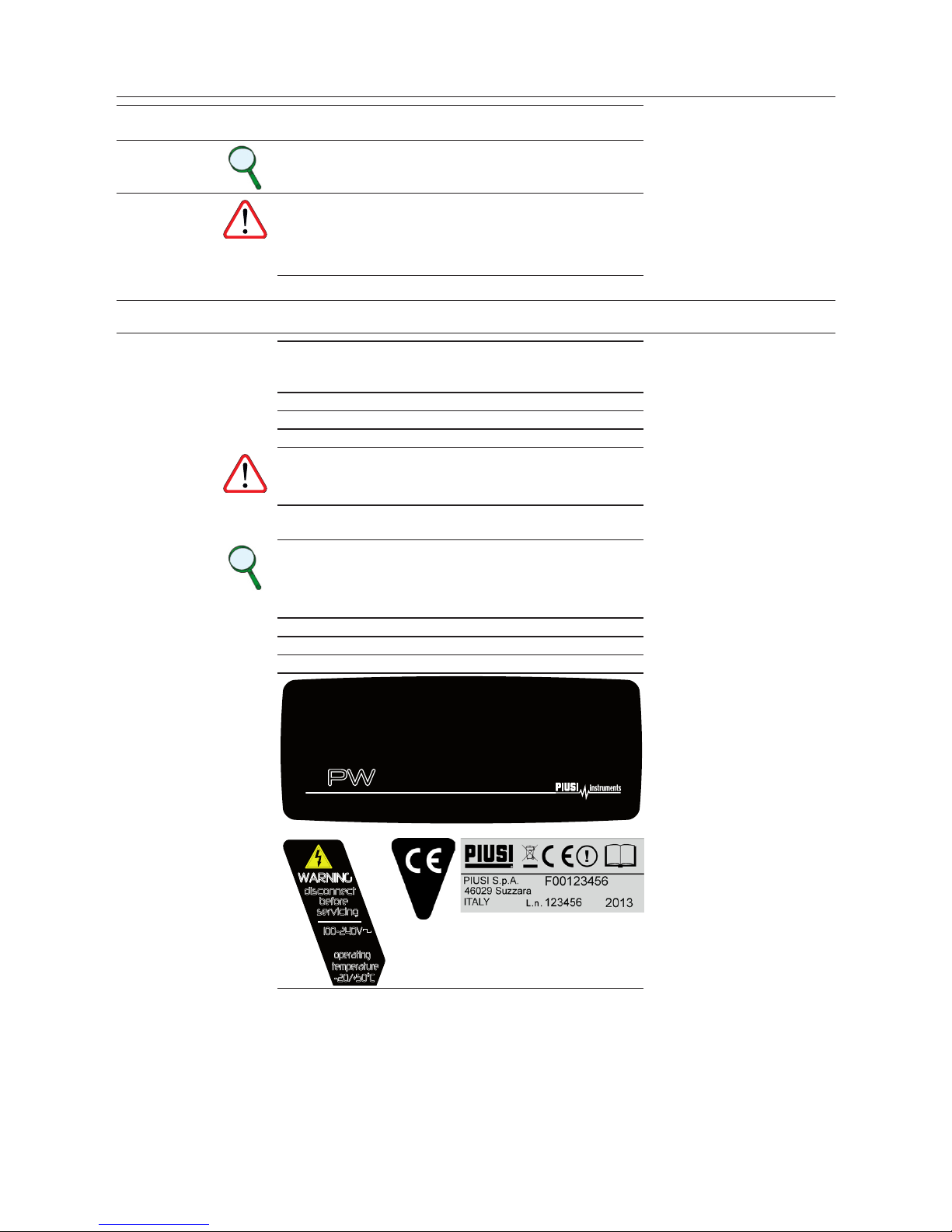
Serial number: refer to Lot Number shown on CE plate axed to product
Year of manufacture: refer to the year of production shown on the CE plate af-
xed to the product
is in conformity with the legal provisions indicated in the directives:
- Electromagnetic Compatibility Directive 2004/108/EC
- Low-Voltage Directive 2006/95/EC
The documentation is at the disposal of the competent authority following
motivated request at Piusi S.p.A. or following request sent to the email address:
up the declaration is Otto Varini as legal representative.
Suzzara, 01/01/2013 Otto Varini
legal representative.
3 GENERAL WARNINGS
Important
precautions To ensure operator safety and to protect the pump
from potential damage, workers must be fully acquaint-
ed with this instruction manual before performing any
operation.
Symbols used
in the manual The following symbols will be used throughout the
manual to highlight safety information and precautions
of particular importance:
ATTENTION
This symbol indicates safe working practices for opera-
tors and/or potentially exposed persons.
WARNING
This symbol indicates that there is risk of damage to the
equipment and/or its components.
NOTE
This symbol indicates useful information.
Manual pres-
ervation
his manual should be complete and legible throughout.
It should remain available to end users and specialist
installation and maintenance technicians for consulta-
tion at any time.
Reproduction
rights All reproduction rights are reserved by Piusi S.p.A. The
text cannot be reprinted without the written permis-
sion of Piusi S.p.A.
THIS MANUAL IS THE PROPERTY OF Piusi S.p.A.
ANY REPRODUCTION, EVEN PARTIAL, IS FORBIDDEN.

M0270 EN 23
EN
4 SAFETY INSTRUCTIONS
4.1 FIRST AID RULES
Persons who
have suered
electric shock
Disconnect the power source, or use a dry insulator to
protect yourself while you move the injured person
away from any electrical conductor. Avoid touching
the injured person with your bare hands until he is far
away from any conductor. Immediately call for help
from qualied and trained personnel. Do not operate
switches with wet hands.
NOTE
Please refer to the safety data sheet for the product

24 M0270 EN
EN
4.2 GENERAL SAFETY RULES
Essential
protective
equipment
characteristics
Wear protective equipment that is:
• suited to the operations that need to be performed;
• resistant to cleaning products.
Personal
protective
equipment that
must be worn
safety shoes;
close-tting clothing;
protection gloves;
safety goggles;
instructions manual
DANGER
The Device is not an anti-explosive type
The device must be installed outside areas at risk of
explosion
Do not install in areas where ammable vapors may
be present
DANGER
The device must be installed under a roof or in any
environment, protected from rain
ATTENTION
The device must be mounted vertically with the grom-
mets facing down
DANGER
Installation operations are carried out with the box
open and accessible electrical contacts. All these ope-
rations have to be done with the unit isolated from the
power supply to prevent electrical shock!
All work related to electrical installation must be per-
formed by qualied installer electrical or electronic.
Wear insulated gloves for electrician.
ATTENTION
As a general rule of electrical safety is always recom-
mended to power the device protecting the line with:
- Switch / breaker with adeguate ampacity to the
power line
- RCD (Residual Current Device) of 30 mA
ATTENTION
Devices must be professionally installed by qualied
and authorized installer and it is the professional instal-
ler’s responsibility to make sure the device is operated
within local country law and regulatory requirements
ATTENTION
The device is intended for use only by professional
sta and authorized

M0270 EN 25
EN
DANGER
The cable must be adapted to the current capacities
of the device.
Never touch the plug and socket with wet hands
Unsuitable extension cable can be dangerous.
In accordance with current regulation only extension
cable that are labelled for outdoor use and have a suf-
cient ampacity should be used outdoor
The connection between plug and socket must stay
away from water.
Before each use, check that the power cable for da-
mage. Replace immediately the cable connection to
the network if it is damaged.
ATTENTION
The maintenance of the electrical parts can ‘be done
only by qualied installer electrical or electronic.
Wear insulated gloves for electrician.
Before performing any maintenance make sure to
unplug the device from the power supply to turn it o
and isolate it from the mains.
If the device is sold without cable to provide periodic
verication of the circuit grounding in accordance
with current regulations.
4.3 PACKAGING
FOREWORD The appliance comes packed in a cardboard box bearing
the following markings:
1 - contents of the
package
2 - weight of the con-
tents
3 - description of the
product

26 M0270 EN
EN
4.4
PACKAGE CONTENTS/PRE-INSPECTION
FOREWORD To open the packaging, use a pair of scissors or a cutter, being
careful not to damage the dispensing system or its components.
NOTES In the event that one or more of the components de-
scribed below are missing from inside the package,
please contact Piusi inc technical support.
WARNING Check that the data on the plate correspond to the
desired specications. In the event of any anomaly,
contact the supplier immediately, indicating the nature
of the defects. Do not use equipment which you suspect
might not be safe.
4.5 MACHINE AND MANUFACTURER IDENTIFICATION
FOREWORD PW-LAN comes with an identication plate; this is
attached externally and contains the following in-
formation:
model
- lot number / Production year;
- technical data;
ATTENTION Before installing, always make sure the type of
dispensing system is correct and suitable for the
available power supply (Voltage/Frequency.)
Make sure that the plate does not deteriorate or be-
come detached over time.
NOTE
Should this situation arise, please contact our
support department and arrange to have the
damaged or missing plates sent back and replaced
where necessary.
The plates are the following:
1 - Front plate 3 - CE mark
2 - Technical Data Plate 4 - CE plate /Lot/Year
WARNING
disconnect
before
servicing
100-240V
50-60Hz/ 15W I P54
operating
temperature
-20/+50°C
KIT LAN CONNECTION
PW -LAN
MADE IN ITALY
1
2
3 4

M0270 EN 27
EN
5 TECHNICAL FEATURES
Dimensions
Length (A) 180 mm
Depth (B) 60 mm
Height (C) 160 mm
Weight 330 g
Technical Specications
Voltage 100 - 230 Vac
Frequency 50 Hz / 60 Hz
Max. power 15 W
Protection grade IP54

28 M0270 EN
EN
6 OVERVIEW
Introduction Welcome to PW-LAN – the new solution which allows you to
connect Piusi devices to your LAN network.
The PW-LAN provides:
•Instant conversion from RS485 to Ethernet signal
•IP Fallback function
•DHCP compatible
•100% compatibility with Piusi Softwares
The PW-LAN is an advanced device capable of powerful and
dierent signal conversion features, built upon a simple and
intuitive user interface foundation.
This User Guide describes the PW-LAN operating system version
3.0, which is integrated into the device.
Supported
Products PW-LAN supports the following Piusi products:
•Self Service FM
•Self Service MC
•Cube MC
•MC-BOX
•OCIO
•MCO
SYSTEM REQUIREMENTS
OPERATING
SYSTEM Microsoft Windows XP
Windows Vista
Windows 7
Windows 8
WEB
BROWSER Mozilla Firefox
Apple Safari
Google Chrome
Microsoft Internet Explorer 8 (or above)
7 INSTALLATION
ATTENTION The installation operations are performed with
door open and power contacts accessible. All these
operations must be performed with the appliance
isolated from the power mains to avoid any risk of
electric shocks!
All the following operations must be performed by
skilled electro-technical or electronic experts
The use of accessories that are unsuitable and were
not provided with the system is strictly prohibited.
Piusi S.p.A. accepts no responsibility for damage
to persons, property or the environment caused by
failure to comply with this requirement.
INSTALL THE APPLIANCE WITH CABLE GLANDS FACING DOWN
AND PROVIDE A PROTECTIVE COVER.

M0270 EN 29
EN
7.1 FIXING TO THE WALL
FOREWORD Remove the front cover to x the PW-LAN on the wall
To fix on the wall, use No. 2 M4 screws
80 3525
15613.5 10
Ø4.5
7.2 WIRE CONNECTION
FOREWORD Removing the frontal case it is possible to make all the
necessary wiring .
To do a proper operation, perform the following steps:
1Fix the the RS485 twisted cable as shown below.
2Fix the three power supply cable as shown below -
Input 100-240 Vac 50/60 Hz.

30 M0270 EN
EN
3Plug in the Ethernet cable
ATTENTION RS485 CABLE
Using a certied cable for rs485 you can reach 1200 meters
ETHERNET CABLE
Use a shielded cable, category 5 or higher. The max. distance
that can be reached is 90 metres. The maximum distance is
also aected by the existing network architecture
WIRED PW-LAN RS485
POWER
ETHERNET
ATTENTION Fix the power cord with the clip provided so that any separation
of the cable from the terminals does not lead to dangerous vol-
tages other cables connected to the outside.

M0270 EN 31
EN
7.3 LED & CONNECTORS
2
3
4
D2 D1
D5 D4
1
1RESET button to restore factory defaults
2Ethernet connector
3RS485 connector
4Power 100/240Vac 50/60 Hz connector
LED FLASHING EQUIVALENCE
D1 OFF No trac from RS485
SLOW
FLASH Trac from RS485
D2
OFF DCHP Disabled, Customized IP (dierent
from 192.168.2.10)
ON DHCP Enabled
SLOW
FLASH DCHP Enabled,
No IP from
DHCP server
Fallback IP
192.168.2.10
FAST
FLASH DHCP Disabled Standard IP 192.168.2.10
D4 ON LAN signal
D5 ON Power ON

32 M0270 EN
EN
7.4 GETTING STARTED
FOREWORD This is the scheme of a typical site structure.
ACCESS To access the PW-LAN Conguration Interface, perform the
following steps
1Make sure that your host machine is connected via Ethernet to
the Piusi device
2Congure the Ethernet adapter on your computer with a static
IP address on the 192.168.2.x subnet (for example, IP address:
192.168.2.150 and subnet mask: 255.255.255.0).
3
Congure internet options of your browser WITHOUT proxy
server
4Launch your Web browser. Enter the default IP address of your
device in the address eld. Press Enter (PC) or Return (Mac).
Device Default IP Address
PW-LAN 192.168.2.10
5Enter admin in the Usernameand piusipass in the Pass-
word elds and click Ok.

M0270 EN 33
EN

34 M0270 EN
EN
7.5 NAVIGATION
FOREWORD
The PW-LAN Configuration Interface contains three main tabs, each of
them provides aWeb-based management page to configure a speci-
fic aspect of the Piusi device:
NETWORK
The “Network Tab” configures the network operating mode; Hostname;
Internet Protocol (IP) settings; DHCP; Subnet Mask; Gateway; Primary and
Secondary DNS Server.
SYSTEM The“SystemTab”. controls administrator account management,
firmware update, and configuration backup.
RS485 The“RS485 Tab” configures the RS485 conversion system, it is pos-
sibile to choose a Piusi product or to set the parameters manually.
7.6 NETWORK TAB
The Network tab allows to configureTCP/IPv4 parameters.
1) Case DHCP Client 2) Case Static IP
ITEM/
SETTING
DEVICENAME Specifies the host name
MANAGEMENTIP
ADDRESS
You chooses the formality of management of the IP of the device among 2 options:
- DHCP Client that it means that in the lan network exist a DHCP server that assigns a dynamic
IP to the PW-LAN , an address IP of the Gateway and an address DNS to the device
- Static that means that the administrator of net assigns a fixed static IP to the PW-LAN.
CURRENTIP
it is the dynamic address that is automatically assigned by the DHCP file server of the lan network to
the PW-LAN
FALLBACKIP
it is the address IP that of default is associated to the PW-LAN if these facts happen:
- the PW-LAN is configured as DHCP Client MA
- after a certain time from the turning of the device the DHCP file server has not succeeded in assign-
ing a dynamic IP and then the PW-LAN configure itself with the IP of FallBack

M0270 EN 35
EN
STATICIP
it is the static lP that the administrator of net manually inserts in the field IP
NETMASK
When the netmask is expanded into its binary form, it provides a mapping to define which portions
of the IP address range are used for the network devices and which portions are used for host de-
vices.The netmask defines the address space of the device’s network segment.The 255.255.255.0 (or
“/24”) netmask is commonly used on many Class C IP networks.
GATEWAYIP Typically, this is the IP address of the host router, which provides the point of connection to
the Internet.This can be a DSL modem, cable modem, orWISP gateway router.The device
directs data packets to the gateway if the destination host is not within the local network.
PRIMARYDNS IP
Specify the IP address of the primary DNS (Domain Name System) server.
SECONDARY
DNSIP
Specify the IP address of the secondary DNS server. This entry is optional and used only if the primary
DNS server is not responding
7.7 SYSTEM TAB
FOREWORD
The“SystemTab”controls the administrator account management.
NEW PASSWORD
Enter the new password for the administrator account.
VERIFYNEWPASSWORD
Re-enter the new password for the administrator account.
7.8 RS485 TAB
FOREWORD The “RS485 Tab”congures the RS485 conversion system
1) Case choice Products Piusi 2) Case Other products
Configuration Default and choice other products PIUSI Setting others Parameters RS485
PIUSI PRODUCT PIUSI PRODUCT: Preset conguration. Choose one of the prod-
ucts in the list.
MANUAL
CONFIGURATION
Manually enter the RS485 parameters.
CUSTOM
PRODUCT This is a four-step procedure:
1Choose the Baudrate
2Choose Databit
3Choose the Parity
4Choose Bit Stop

36 M0270 EN
EN
7.9 PROCEDURE TO RESTORE
FACTORY SETTINGS
If you are no longer able to access the device and you want to reset the
factory settings, a special Reset procedure should be applied.
ATTENTION The procedure must be done only by sta experi-
enced on the dangers of the electrical power!
The sta must wear insulating gloves in order
to
The procedure is as fo lplorwevse:
1) Remove supply voltage to the device
2) Open the box with the 4 screws
3) Locate the RESET button
as shown in the previous paragraphsi
4) Press and hold the RESET button while you
power
ATTENTION This procedure is very dangerous because you are near points
with dangerous voltage on the board.
Use insulating gloves for electricians!

8 DISPOSAL
Foreword If the system needs to be disposed, the parts which make
it up must be delivered to companies that specialize in the
recycling and disposal of industrial waste and, in particular:
Disposing of pack-
ing materials The packaging consists of biodegradable cardboard which
can be delivered to companies for normal recycling of cel-
lulose.
Metal Parts Dis-
posal Metal parts, whether paint-nished or in stainless steel, can
be consigned to scrap metal collectors.
Disposal of electric
and electronic
components
These must be disposed of by companies that specialize in
the disposal of electronic components, in accordance with
the indications of directive 2002/96/CE (see text of directive
below).
Informa-
tion regard-
ing the en-
vironment
for clients
residing
within the Euro-
pean Union
European Directive 2002/96/EC requires that all equipment
marked with this symbol on the product and/or packaging
not be disposed of together with non-dierentiated urban
waste.The symbol indicates that this product must not be
disposed of together with normal household waste. It is the
responsibility of the owner to dispose of these products
as well as other electric or electronic equipment by means
of the specic refuse collection structures indicated by the
government or the local governing authorities.
Miscellaneous
parts disposal Other components, such as pipes, rubber gaskets, plastic
parts and wires, must be disposed of by companies special-
ising in the disposal of industrial waste.


Table of contents
Other Piusi Dispenser manuals

Piusi
Piusi MC BOX 1.5 ETL User manual

Piusi
Piusi SB325M Use and care manual

Piusi
Piusi MC BOXdc B.SMART Quick start guide

Piusi
Piusi Cube 56/33 User manual

Piusi
Piusi CUBE B.SMART Quick start guide

Piusi
Piusi SUZZARABLUE PRO User manual

Piusi
Piusi MC BOX B.SMART Specification sheet

Piusi
Piusi DELPHIN PRO Quick start guide

Piusi
Piusi CUBE 70 MC User manual

Piusi
Piusi Cube 56/33 Installation and operating instructions