Alfalaval Mini ECO User manual

DOC-1390, 2016-22
Installation and operating
Alfa Laval Mini ECO
EN
SV
FR


3
EN
SV
FR
Alfa Laval Mini ECO
Installation and service 4
Installation och drift 14
Installation et utilisation 25
Electrical connections / Elektriska kopplingar /
Raccordements électriques 35
Packing list / Packlista / Liste de colisage 36
Declaration of conformity / Försäkran om överensstämme /
Déclaration de conformité 37

Alfa Laval Mini ECO
Installation and operating
4
DOC-1390EN, 2016-22
Installation and service
Contents
Product overview Mini ECO........................................................................61
Installation...................................................................................................72Unpacking.....................................................................................................72.1 Preparation....................................................................................................72.2 Mounting the substation ................................................................................72.3 Filling up the system......................................................................................72.4
2.4.1 Filling up the tap water circuit..................................................................8
2.4.2 Filling up and bleeding the heating circuit................................................8
2.4.3 Connecting to heating network................................................................8
Connecting the electrical equipment..............................................................82.5 Under floor heating thermostat ......................................................................92.6
2.6.1 Settings for under floor heating ...............................................................9
Commissioning advice Mini ECO.................................................................102.7 General adjustments and settings ...............................................................102.8 Installing the room thermostat .....................................................................112.9 Installing the outdoor temperature sensor....................................................122.10 Starting up sequence for Mini ECO with component check..........................122.11
Room thermostat.......................................................................................133Control modes.............................................................................................133.1 Changing the control mode..........................................................................133.2
For additional online information and manual:
URL address:
http://www.alfalaval.com/mini-eco
QR-code:

Alfa Laval Mini ECO
Installation and operating
5
EN
The installation work must be carried out by an authorized installation
contractor. Before the system is taken into operation, it must be pressure
tested in accordance with relevant regulations.
The temperature and the pressure of the primary heating water are very
high. Only qualified technicians are allowed to work with the substation.
Incorrect operation may cause serious personal injury and result in
damage to the building.
If the hot water temperature is set too high, people may be scalded. If the
hot water temperature is set too low, unwanted bacteriological growth may
occur in the hot water system. This can result in serious personal injury.
Parts of the substation may get very hot and should not be touched.
When starting up the substation: To avoid the risk of scalding,
make sure that no-one draws any hot water until the hot water
temperature has been adjusted.
Start heating circulation by first opening the valves in the primary heating
supply and then return lines, in order to avoid pollutions in the system.
Open up the valves slowly to avoid pressure surges.
Before the substation is connected to the electrical supply, make sure that
the heating system is topped up with water. Starting up the system without
water will damage the circulation pump.
The substation comes prepared with an electrical plug to be connected to
the main supply. If necessary, the plug-and-socket connection can be
replaced with a permanent installation with an all-pole isolate switch. This
must be carried out by a qualified electrician.

Alfa Laval Mini ECO
Installation and operating
6
Product overview Mini ECO1
Note: the picture shows the F2 version
1.
Heat exchanger and temperature
controller for hot water
17.
Cold water outlet (cw)
2. Control valve for hot water 18. Hot water (hw)
3. Heat exchanger for heating 20. Heating circuit, return
4.
Control valve, heating circuit
21.
Heating circuit, supply
5.
Actuator, heating circuit
22.
Drain valve
6.
Temperature sensor connection,
heating media supply
24.
Connection box for electric power and
sensors, heating circuit
7. Filter for heating media 25. Room thermostat/control panel
8. Adapter for energy meter 26. Outdoor temperature sensor
9.
Check valve for cold water
27.
Filter heating circuit
10.
Adapter for Cold water flow meter
28.
Pressure gauge for heating circuit
11.
Safety valve for domestic hot water
29.
Filling valve
12.
Adapter for Hot water flow meter
30.
Safety valve for heating circuit
13. Safety temperature limiter hot water 31. Expansion vessel heating circuit
14.
Heating network media, supply
(primary inlet)
32.
Circulation pump, heating circuit
15.
Heating network media, return
(primary return)
33.
Supply temperature sensor, heating
circuit
16.
Cold water (cw)

Alfa Laval Mini ECO
Installation and operating
7
EN
Installation2
Unpacking2.1
•Remove the transport packaging and check that the product has not been damaged
in transit and that the consignment agrees with the specifications.
•When lifting the unit take care not to apply stress to pipes and heat exchanger as this
may weaken them. Avoid lifting the unit by holding the heat exchanger.
Note: Risk of injury lifting heavy objects.
Preparation2.2
•Mini ECO must be placed on a wall, in upright position. Use screws or bolts suitable
for the material of the wall and for the weight of the unit.
•Choose a suitable installation area in accordance with official regulations.
The substation may generate sounds during operation caused by pumps, regulators
systems, flows etc. This should be taken in consideration during installation of the unit
so that possible operational sounds affect the surroundings as little as possible.
Alfa Laval recommends that the substation is mounted on well-insulated walls, such
as outer walls or on concrete walls.
•Check the applicable regulations of the primary heating supplier.
The available differential pressure should be at least 50 kPa and at most 600 kPa.
•Where the differential pressure is higher, a differential pressure controller should be
added to the installation.
Mounting the substation2.3
•Before mounting the substation tighten the pipe connection Heating network media,
supply and Heating network media, return with 45 Nm.
•Mount the substation on the wall with four screws.
Alfa Laval recommends having 900mm from floor to the substation.
•Place gaskets on the valves and use hand power and fasten the nuts to the pipes on
the substation.
•Tighten with 45 Nm.
•Close all valves.
•Connect the pipe work to the valves.
The temperature and the pressure of the primary heating water are very
high.
Only qualified technicians are allowed to work with the substation.
Incorrect operation may cause serious personal injury and result in
damage to the building.
•Energy meters, see 1 Product overview Mini ECO, must be installed at a prepared
location, replacing a gauge block, or following the instructions of the energy supplier.
•Mount the provided draining pipe to the safety valve on the cold water circuit.
•Connect a hose or a pipe from the safety valves to the floor gully.
Filling up the system2.4
•Fill up the system with water by opening the valves on the incoming pipes.

Alfa Laval Mini ECO
Installation and operating
8
The valves must be opened in the correct order in order to avoid pollutions
in the system.
Open up the valves slowly to avoid pressure surges.
Filling up the tap water circuit2.4.1
•Open the valves Cold water, Cold water outlet and Hot water.
•Open all water taps in the building to get rid of trapped air. Let them be open until all
air is gone.
Filling up and bleeding the heating circuit2.4.2
•Attach the long provided filing hose between the filling valves, to fill up the heating
circuit.
•Open the valves Heating circuit return and Heating circuit supply.
•Open the filling valves.
•Fill up the system until the manometer shows 1,6 Bar.
•Close the filling valves.
•Bleed the heating system via the draining valves and at the heating systems draining
places e.g. radiator valves.
•If the pressure is low after bleeding the system, open the filling valves and fill up to
1,6 Bar again.
•The first time the heating system is filled up, this procedure might have to be
repeated several times.
•When the pressure is correct and the heating system is drained from air, remove the
filing hose.
Connecting to heating network2.4.3
•Open the valves Heating network media, supply and Heating network media, return.
Start with supply then return.
•When all water connections are done and all circuits are pressurized, look for leaks.
•If connections need retightening after the installation has been taken into service, the
system must be depressurised. If the system is not depressurised, gaskets will be
damaged.
Connecting the electrical equipment2.5
•Remove the lid that covers the connection box and loosen the connection box from
the insulation.
1
Outdoor temperature sensor
2
Room thermostat
3 Supply temperature sensor
4
Actuator, heating
5
Power cable adapter

Alfa Laval Mini ECO
Installation and operating
9
EN
•Install the room thermostat; see 2.9 Installing the room thermostat.
•Connect the non-polarity contact, from room thermostat to the connection box.
Carefully press the cable into the trail in the insulation.
•Mount the outdoor temperature sensor on the north side of the building,
2 metres above the ground, or higher.
See 2.10 Installing the outdoor temperature sensor.
•Connect the non-polarity contact from outdoor temperature sensor to the connection
box. Carefully press the cable into the trail in the insulation.
•Connect the correct power cable to connection box and press down the cable and
box it into the insulation.
•Place the lid over the connection box.
•Put the electrical cable into a wall outlet.
See 2.11 Starting up sequence for Mini ECO with component check.
•Mount the cover. Always use the handles on the side when handling the cover.
Under floor heating thermostat2.6
Heating systems with under floor heating have to be equipped with a heating thermostat. If
the heating system is not equipped with the thermostat, the under floor heating system and
floors in general might get damaged.
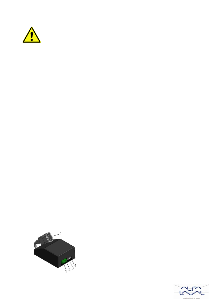
•Disconnect the substation electrical power supply
cable. Disconnect the electrical plug on the circulation
pump.
•Connect the new power supply cable from the
electrical box to the circulation pump.
•Reconnect the existing power supply cable to the
connection on the electrical box.
•Attach all electrical wires with the necessary amount of
straps. It is important not to attach electrical wires on
primary heating pipes and sharp edges.
•Change parameters and recommended settings before
starting up the system with an under floor heating
thermostat.
Settings for under floor heating2.6.1
The following changes must be done before starting up Mini City with an under floor
heating thermostat.
1) Change the pump operating mode to constant pressure.
For more information see manual
Installation Service And Operating Instruction Mini City
on http://www.alfalaval.com/mini-eco.
2) Change the supply temperature to maximum 45°C.
See 3.2 Changing the control mode.
3) Change room thermostat heat curve to 5.
See 3.2 Changing the control mode.

Alfa Laval Mini ECO
Installation and operating
10
Commissioning advice Mini ECO2.7
•Adjust the hot water temperature by having a hot water tap open at normal flow rate.
Measure the temperature at the draw-off point with a thermometer. It takes about 20
seconds to get a stable tap water temperature.
The temperature should be minimum 50°C.
Alfa Laval recommends that the primary inlet temperature is at least 10º higher than
the tap water temperature.
NOTE: Make sure that no cold water is mixed with the hot water while making this
adjustment.
Seal the hot water actuator after setting.
•The room thermostat has been pre-set at the factory to use control mode; Outside
Temperature Control (OTC control).
To change control mode see 3 Room thermostat .
General adjustments and settings2.8
The property owner must be instructed in the operation, setting and care of the unit.
It is particularly important to provide information about the safety systems and about
hazards that may arise in relation to the high pressure and temperature of the primary
heating water.

Alfa Laval Mini ECO
Installation and operating
11
EN
Installing the room thermostat2.9
1 Removing power supply
2 Placement
3 Removing the dial
4 Removing the thermostat
5a Mounting direct on the
wall
5b Mounting in wall
socket
6 Connecting the cable
7 Mounting the thermostat
8 Mounting the dial

Alfa Laval Mini ECO
Installation and operating
12
Installing the outdoor temperature sensor2.10
Connect the outdoor temperature sensor to the connection box.
With a conductor area of 0.6 mm2the maximum cable length is 50 metres, maximum
5 Ω/conductor.
If the outdoor temperature sensor is connected at a later time, for example in a
construction period, the room thermostat must be restarted.
Control mode 2 and 3 requires an outdoor temperature sensor.
Starting up sequence for Mini ECO with component check2.11
Note: The substation must be filled with water before starting the room thermostat, if not
the pump can be damage.
The room thermostat controls the supply temperature to the heating system. The room
thermostat is pre-set to use control mode 2, Outside Temperature Control (OTC control).
•Put the electrical cable from the connection box into a wall outlet.
•We recommend using an earth fault breaker.
•A check of the actuator and pump function starts.
During start-up sequence, the components manoeuvres by the following schedule:
o10s actuator closes
o10s actuator opens
o10s actuator closes
o10s pump runs
o150s actuator closes.
oThe next five minutes, the pump starts running and control begins to regulate to
37°C.
Note: Under certain operating conditions, 37°C is not reached within 5 min. The
Actuator knob should however have moved counter clockwise.
•When start-up sequence is completed the room thermostat returns to last set control
mode.
Note: If there is no heat demand the pump stops after the start-up sequence.

Alfa Laval Mini ECO
Installation and operating
13
EN
Room thermostat3
1
LCD display
2
Dial
3
Right touch button
4
Left touch button
Control modes3.1
The room thermostat has five different control modes to select between; the default mode
is Outside Temperature Control (OTC control).
1. Room temperature control (RTC)
Supply setpoint is calculated based on the room temperature setpoint and the actual
room temperature.
2. OTC control
Require a connected outdoor temperature sensor.
Supply setpoint is purely based on the outside temperature.
3. OTC control with room temperature compensation (OTC+RTC)
Require a connected outdoor temperature sensor.
Supply setpoint is based on the outside and room temperature.
4. Constant supply temperature with Heat demand input
Use with dual zone system, underfloor heat demand system with several zones or
any heat demand system.
Select a fixed supply temperature setpoint. This setpoint is always active.
NOTE: Does not work with an outdoor thermostat connected.
5. Constant supply temperature
Use with a flow switch
Select a fixed supply temperature setpoint. This setpoint is always active.
NOTE: Does not work with an outdoor thermostat connected.
Changing the control mode3.2
Three different settings can be done:
oControl mode (1-5)
oHeating curve (4-40)
oMax supply temperature (30°-80°C)
•Turn the dial down to 10°C.
•Enter the setting menu by pressing both right and left touch button for 10 seconds.
•Use the dial to choose control mode, 1-5.
Confirm the choice within 10 sec by pressing the left touch button.
•Choose the heating curve with the dial, 4-40.
Confirm the choice within 10 sec by pressing the left touch button.
•Choose max supply temperature with the dial, 30°-80°C.
Confirm the choice within 10 sec by pressing the left touch button.
•When all settings are done wait a few seconds and the room thermostat automatically
leaves the setting menu.
•Restart the room thermostat after changing the control mode.

Alfa Laval Mini ECO
Installation och drift
14
DOC-1390SV 2016-22
Installation och drift
Innehåll
Produktöversikt Mini ECO ........................................................................161
Installation.................................................................................................172Uppackning.................................................................................................172.1 Förberedelser..............................................................................................172.2 Montering av centralen................................................................................172.3 Påfyllning av systemet.................................................................................172.4
2.4.1 Påfyllning tappvatten krets....................................................................18
2.4.2 Påfyllning och avluftning av värme systemet.........................................18
2.4.3 Anslutning till värmenätverket................................................................18
Anslutning av elektroniken...........................................................................182.5 Golvvärmetermostat....................................................................................192.6
2.6.1 Inställningsvärden för golvvärme...........................................................19
Driftsättning Mini ECO.................................................................................202.7 Allmänt........................................................................................................202.8Installation av rumstermostat.......................................................................212.9 Installation av utegivaren.............................................................................222.10 Uppstart sekvens för Mini ECO med komponent kontroll.............................222.11
Rumstermostat..........................................................................................233Driftläge.......................................................................................................233.1 Ändra driftläge.............................................................................................243.2
För mer information, manual och installations film
URL adress:
http://www.alfalaval.com/mini-eco
QR-kod:

Alfa Laval Mini ECO
Installation och drift
15
SV
Installationen måste utföras av en auktoriserad installatör. Innan systemet
tas i bruk måste det trycktestas enligt gällande regler.
Hetvattnet från värmenätverket har mycket hög temperatur och tryck.
Endast behöriga tekniker får arbeta med värmecentralen. Felaktig drift
kan leda till allvarliga personskador och skada byggnaden.
Hög tappvarmvattentemperatur kan orsaka personskada genom skållning.
Om varmvattentemperaturen är för låg kan det leda till oönskad
bakterietillväxt i varmvattensystemet. Detta kan leda till allvarliga
personskador.
Delar av centralen kan bli mycket varma och bör därför inte vidröras.
Vid igångkörning av värmecentralen, för att undvika skållningsrisk, se till
att ingen använder tappvarmvatten innan varmvattentemperaturen har
justerats.
Vid uppstart av värmesystemet: öppna värmenätverk tillopp och
därefter retur, detta för att undvika att föroreningar kommer in i
systemet. Öppna avstängningsventilerna långsamt för att undvika
tryckstötar.
Innan värmecentralen ansluts elektriskt ska värmesystemet på
sekundärsidan vara påfyllt. Startas systemet upp utan vatten kommer
cirkulationspumpen att skadas.
Värmecentralen levereras med en kontakt för anslutning till elnätet.
Vid behov kan anslutningen med stickkontakt ersättas av en flerpolig
brytare. Detta måste utföras av en behörig elektriker.

Alfa Laval Mini ECO
Installation och drift
16
Produktöversikt Mini ECO1
OBS: Bilden visar version F2.
1
Värmeväxlare, inkl. utrustning för
temperaturreglering av varmvatten
17
Kallvatten, utlopp
2 Styrventil, varmvatten 18 Varmvatten
3 Värmeväxlare, värme 20 Värmekrets, retur
4
Styrventil, värmekrets
21
Värmekrets, tillopp
5
Ställdon, värmekrets
22
Avluftningsventil
6
Anslutning för temperaturgivare,
värmenätverk tillopp
24
Kopplingsbox för el och givare,
värmekrets
7
Filter, värmenätverk
25
Rumstermostat/ kontrollpanel
(visas inte i bilden)
8
Passbit, energimätare
26
Utegivare
(visas inte i bilden)
9 Backventil kallvatten 27 Filter, värmkrets
10 Passbit, kallvattenmätare 28 Manometer, värmekrets
11
Säkerhetsventil tappvarmvatten
29
Påfyllningsventil
12
Passbit, varmvattenmätare
30
Säkerhetsventil, värmekrets
13
Säkerhetstemperaturbegränsare,
varmvatten
31
Expansionskärl värmekrets
14
Värmenätverk, tillopp (primär tillopp)
32
Cirkulationspump, värmekrets
15
Värmenätverk, retur (primär retur)
33
Framledningstemperaturgivare,
värmekrets
16
Kallvatten

Alfa Laval Mini ECO
Installation och drift
17
SV
Installation2
Uppackning2.1
•Ta bort förpackningsmaterialet och kontrollera att produkten inte har skadats under
transporten samt att leveransen stämmer med specifikationerna.
•Lyft enheten försiktig så att rör och värmeväxlaren inte utsätts för påfrestningar, detta
kan försvaga dem. Undvik att hålla i värmeväxlaren under lyft.
OBS:Risk för personskada, värmecentralen är tung.
Förberedelser2.2
•Mini ECO måste placeras på en vägg, i upprätt position.
Använd skruvar eller bultar som är lämpliga för väggmaterialet och centralens vikt.
•Välj en lämplig installationsplats enligt de officiella bestämmelserna. Värmecentralen
kan generera vissa ljud såsom pumpljud, strömningsljud och ljud från
reglerutrustning. Vid installation av centralen bör man beakta detta och placera den
på sådant sätt att eventuella driftsljud påverkar omgivningen så lite som möjligt.
•Alfa Laval rekommenderar att värmecentralen placeras på en stabil isolerad vägg
såsom yttervägg eller vägg av betong.
•Kontrollera gällande bestämmelser från värmeleverantören.
Det tillgängliga differenstrycket ska vara minst 50kPa och högst 600 kPa.
•Om differenstrycket är högre måste en differenstrycksregulator installeras.
Montering av centralen2.3
•Innan centralen monteras; efterdra kopplingarna till Värmenätverk, tillopp och retur
med 45 Nm.
•Montera centralen på väggen med fyra skruvar.
Alfa Laval rekommenderar 900 mm från golvet till central.
•Lägg packningar på ventilerna, dra för hand alla muttrarna mot rören på centralen.
•Dra med 45 Nm.
•Stäng alla ventiler.
•Anslut samtliga rör till ventilerna.
Hetvattnet från värmenätverket har mycket hög temperatur och tryck.
Endast behöriga tekniker får arbeta med värmecentralen. Felaktig drift
kan leda till allvarliga personskador och skada byggnaden.
•Energimätare måste installeras på förberedd plats istället för mätarblock, eller enligt
energileverantörens anvisningar.
•Montera spillröret till säkerhetsventilen på kallvattensidan.
Anslut en slang eller ett rör från säkerhetsventilerna till en golvbrunn.
Påfyllning av systemet2.4
Fyll upp systemet med vatten genom att öppna ventilerna på de inkommande rören.
Ventilerna måste öppnas i rätt ordning för att undvika att föroreningar
kommer in i systemet.
Öppna ventilerna långsamt för att undvika tryckstötar.

Alfa Laval Mini ECO
Installation och drift
18
Påfyllning tappvatten krets2.4.1
•Öppna ventilerna Kallvatten inlopp, Kallvatten utlopp och Varmvatten.
•Öppna alla vattenkranar i huset för att bli av med luft i vattenledningarna.
Påfyllning och avluftning av värme systemet2.4.2
•Anslut den långa slangen mellan påfyllningsventilerna.
•Öppna ventilerna Värmekrets retur och Värmekrets tillopp.
•Öppna påfyllningsventilerna.
•Fyll upp systemet tills manometern visar 1,6 Bar.
•Stäng påfyllningsventilerna.
•Lufta värmesystemet via avluftningsventilerna och på värmesystemets
avluftningspunkter, exempelvis på radiatorventilerna.
•Om trycket är mycket lågt efter luftningen av systemet, öppna påfyllningsventilerna
och fyll upp till 1,6Bar igen.
•Första gången systemet fylls upp kan denna procedur behöva upprepas ett antal
gånger.
•När systemet är fullt och avluftat, ska påfyllningsslangen tas bort.
Anslutning till värmenätverket2.4.3
•Öppna ventilerna Värmenätverk tillopp och Värmenätverk retur.
Börja med tillopp sen retur.
•När alla kopplingar är gjorda och alla kretsar är trycksatta, kontrollera att det inte finns
några läckor.
•Om en koppling behöver efterdras efter att systemet är taget i drift, måste systemet
göras trycklöst, annars kommer packningarna att skadas.
Anslutning av elektroniken2.5
•Ta bort locket som täcker kopplingsboxen. Lossa försiktigt kopplingsboxen från
isoleringen.
1
Utegivare
2 Rumstermostat
3
Temperaturgivare, värme tillopp
4
Ställdon, värme
5
Adapter till spänningskabel
•Installera rumstermostaten, se 2.9 Installing the room thermostat.
•Anslut kabeln från rumstermostaten till kopplingsboxen.
Kontakten är polaritetsoberoende.
Tryck försiktigt ner kabeln i spåret i isoleringen.
•Montera utegivaren på byggnadens norra sida, 2 meter från marken eller högre. För
inkoppling av utegivaren se 2.10 Installation av utegivaren.

Alfa Laval Mini ECO
Installation och drift
19
SV
•Anslut kabeln från utegivaren till kopplingsboxen.
Kontakten är polaritetsoberoende.
Tryck försiktigt ner kabeln i spåret i isoleringen.
•Anslut rätt spänningskabel till kopplingsboxen, pressa ner kabel och kopplingsbox i
isoleringen.
•Sätt tillbaka locket över kopplingsboxen.
•Anslut spänningskabeln till ett nätuttag.
Se 2.11 Starting up sequence for Mini ECO with component check.
•Montera kåpan. Håll alltid i handgreppen när kåpan monteras eller demonteras.
Golvvärmetermostat2.6
Vid anslutning av värmesystem med enbart golvvärme ska värmecentralen utrustas med
termostatskydd. Om värmecentralen inte förses med denna termostat kan
golvvärmesystemet samt golvkonstruktioner skadas p.g.a. hög temperatur.
•Gör centralen spänningslös, ta bort spänningskabeln
till cirkulationspumpen.
•Anslut den nya spänningskabeln från elboxen till
cirkulationspumpen.
•Anslut den gamla spänningskabeln till
cirkulationspumpen mot den kapslade elboxen, i
avsedd anslutning.
•Montera termostaten.
•Fäst elkablar med buntband. Det är viktigt att inte
montera kablar på värmerör och skarpa kanter.
•Ställ in berörda parameterar och rekommenderade
inställningar innan systemet startas igång med
golvvärmetermostaten.
Inställningsvärden för golvvärme2.6.1
Följande inställningar måste göras innan Mini City startas med en golvvärmetermostat.
1) Ändra pumpens driftläge till konstant tryck.
För mer information se manualen:
Installation Service And Operating Instruction Mini City
på http://www.alfalaval.com/mini-eco
2) Ändra tilloppstemperaturen till max 45°C.
Se 3.2 Ändra driftläge.
3) Ändra rumstermostatens värmekurva till 5
Se 3.2 Ändra driftläge

Alfa Laval Mini ECO
Installation och drift
20
Driftsättning Mini ECO2.7
•Justera varmvattentemperaturen genom att låta en varmvattenkran rinna med
normalt flöde en stund. Mät temperaturen vid tappstället med en termometer.
Stabiliseringstiden är cirka 20 sekunder.
Varmvattentemperaturen bör ställas till minst 50 ºC.
Alfa Laval rekommenderar att primär tilloppstemperatur är minst 10 grader högre än
inställd varmvattentemperatur.
OBS: Se till att inget kallvatten blandas med varmvattnet när denna justering utförs.
Plombera varmvattenställdonet efter inställning
•Rumstermostaten är fabriksinställd att använda driftläge, utomhuskompensering.
För att ändra driftläge, se 3 Rumstermostat.
Allmänt2.8
Fastighetsägaren måste informeras om hur man använder, ställer in och underhåller
enheten. Det är särskilt viktigt att informera om säkerhetssystemen och om risker som kan
uppstå i samband med det höga tryck och temperaturen på vattnet från värmenätverket.
Other manuals for Mini ECO
2
Table of contents
Languages:
Other Alfalaval Recording Equipment manuals