Wintriss ShopFloorConnect SMI 2 User manual

By
Wintriss Controls Group
Addendum –SMI 2 –User Guide
ShopFloorConnect Machine Interface
1146200 –Rev. C
October 27, 2021
SFC Support Hotline 800-586-8324 (Option 3) 8-5 EST

Addendum October 2021 1146200
SMI 2 User Guide Rev. C Page 1
Contents
Specifications ................................................................................................................................................3
Main Menu....................................................................................................................................................4
Main Menu Icon/Button Selections..............................................................................................................5
Dashboard.....................................................................................................................................................6
Downtime......................................................................................................................................................7
Job Manager .................................................................................................................................................8
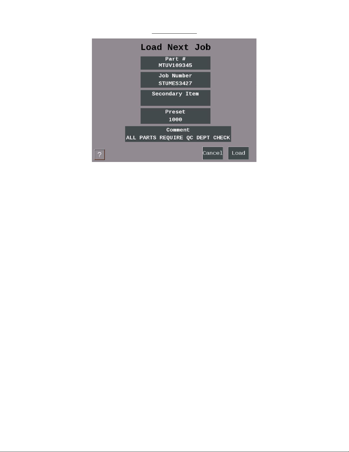
Load Next Job................................................................................................................................................9
Preset..........................................................................................................................................................10
Batch Segment Preset.................................................................................................................................11
Admin Menu ...............................................................................................................................................12
Security Settings..........................................................................................................................................13
Confirm Reset to Factory Defaults..............................................................................................................14
About SMI ...................................................................................................................................................15
Multipliers...................................................................................................................................................16
Utilities........................................................................................................................................................17
Additional Settings - Icon/Button Selections..............................................................................................18
Screen Defaults...........................................................................................................................................19
Forced Dialog Settings ................................................................................................................................20
Scanner Defaults.........................................................................................................................................21
Production Settings.....................................................................................................................................22
Input Settings..............................................................................................................................................23
Input Setup..................................................................................................................................................24
Cycle Input Setup ........................................................................................................................................25
Run/Idle Input Setup...................................................................................................................................26
Rate Calculation..........................................................................................................................................27
Analog Setup Menu.....................................................................................................................................28
Enable Inputs ..............................................................................................................................................29
Production Parameter Download ...............................................................................................................31
SMI 2 Job Manager Settings........................................................................................................................32
Forced Operator Login................................................................................................................................33
Network Settings.........................................................................................................................................34
Network IP Settings.....................................................................................................................................35
Wireless Settings.........................................................................................................................................36

Addendum October 2021 1146200
SMI 2 User Guide Rev. C Page 2
Figures at End of User Guide
Figure 1 –SFC Machine Interface 2
Figure 2 –SFC Machine Interface 2 (Press Wiring Diagram)
Figure 2 - SFC Machine Interface 2 (24 VDC Wiring Diagram)
ADDENDUM - SMI 2 User Guide
This User Guide is intended to be used –on an interim basis - in conjunction with the SMI 2 user
manual while the final manual is completed. Included are explanations of the modified SMI 2 Menus
and new settings. This guide applies to HMI code version 3.63. For older version some features may
not be available.
NOTE: There is a 30-character limit on all entry fields (with one exception –See below). Allowable
characters include numbers, upper and lowercase letters, spaces, and the special characters:
.- _[ ] { } \=* # + ~ % $
Data can be entered into the fields manually, or by the use of a scanner connected to the SMI 2’s USB
port.
The one exception to the 30-character limit is the Primary when it is set to ‘Tool # (123)’. This
particular primary type is intended to match the Wintriss SmartPAC 1 and SmartPAC 2 controls and is
limited to 7 numeric characters only.
Note: Not all the available Icon/Buttons and their data fields in the SMI 2 are applicable to all machine
types. When a data field does not apply to a specific application, it can be hidden. This guide shows all
the data entry fields. If your SMI 2 does not show a particular field, it is likely hidden because it is not
needed. To identify which Icon/Buttons and their data entry fields can be hidden from the main menu,
refer to the Icon/Buttons table (See page 4).

Addendum October 2021 1146200
SMI 2 User Guide Rev. C Page 3
Specifications
Installation
Category
II
Dimensions
Enclosure: 8.00 x 10.08 x 4.00 in. (101.6 x 203.2 x 256.0 mm) NEMA 12, IP 66
Panel mount: 9.2 x 7.7 x 4.25 in. (234 x 196 x 108 mm)
Electrical
(System Power)
Input: 100-240 Vac, 40 W, 50-60 Hz
or
24 Vdc +/- 15%, 30 W
When installed, this equipment shall have, in close proximity and easily
accessible, a switch or circuit breaker marked as the disconnect switch.
Operating
Environment
Indoor use only
Temperature: 32o to122o F (0o to50o C)
Relative Humidity: Indoor factory conditions
Altitude: 6562 ft (2000 m)
Parts Counter
Total preset for maximum count. Set to 9 digits.
Batch Preset for maximum count. Set to 7 digits.
Inputs
All SMI 2 inputs (sink or source): 9mA ± 2 mA @ 24 Vdc
TB2 Inputs 1-4 (Factory Wired for PNP)
1. Cycle Count
2. Run/Idle
3. Scrap
4. Setup
TB4 Automatic Downtime Inputs 1-4 (Factory Wired for PNP)
1. Downtime Reason 32
2. Downtime Reason 31
3. Downtime Reason 30
4. Downtime Reason 29
Outputs
1 stop circuit (dry contacts): Contact rating 4 A, max, @240 Vac or 30 Vdc
Scanner
(optional)
USB barcode scanner capable of adding a carriage return as a suffix
Wireless
Connection
(optional)
Factory installed
IEEE 802.11 b/g/n

Addendum October 2021 1146200
SMI 2 User Guide Rev. C Page 4
Main Menu
Figure 1 - SMI 2 Main Menu
The Status Banner at the top of the main menu is color-coded for the five different SFC states: Green
(Running), Blue (Idle), Red (Unplanned), Yellow (Changeover), Purple (Planned). It also shows the
current status and duration as well as the current count info and production rate.

Addendum October 2021 1146200
SMI 2 User Guide Rev. C Page 5
Main Menu Icon/Button Selections
Select the ‘Operator’icon to enter the operator number or name (Optional Scan Field).
Select the ‘Rejects’(scrap) icon to manually enter the desired quantity of defective parts.
Select the ‘Job Manager’icon to enter job related information, start a new job or to end
the current job.
Select the ‘Dashboard***’icon to show MTBF (Mean Time Between Failures) and Analog
Channel values.
Select the ‘Hold State***’to hold the current Planned/Unplanned downtime or
Changeover state and prevent the SMI from counting until it is selected again and
disabled. Hold State is often used when setting up the machine.
Select the ‘Return to Production’icon when first powering up, to end a downtime event
or if a count preset is reached. By selecting ‘Return to Production’ icon it will change the
state to an idle state.
Select the ‘Dialog Menu’icon to select an applicable Downtime Reason code as to why
the machine is down (Used when machine is not running and before or after a forced
dialog reason is entered).
Select the gear icon to access the ‘Admin Menu’.
Select the question mark icon (bottom left) for a series of help topics related to the
menu or menu item that is in view.
These are the main menu Icon/Buttons and their functions (an *** indicates that the button may be
hidden via a selection in the ‘Admin Settings’ menu):

Addendum October 2021 1146200
SMI 2 User Guide Rev. C Page 6
Dashboard
Figure 2 - Dashboard Menu
The DASHBOARD menu shows MTBF (Mean Time Between Failures) and the Analog values from any
connected analog sensor (e.g. Temperature, Current, Pressure, etc.).
Mean time between failures (MTBF) refers to the average amount time between Unplanned Downtime
occurrences.
Note: The Dashboard menu is disabled by default. The current functionality can be used for displaying
analog channels however, enhanced features will be available soon in a future release. For more
information on this feature and availability, please contact SFC Technical Support 800-586-8324
(Option 3).

Addendum October 2021 1146200
SMI 2 User Guide Rev. C Page 7
Downtime
Figure 3- The Downtime Menu
Use this menu to choose the appropriate downtime reason. Use the ‘Previous’or ‘Next’buttons to
display the previous or next set of reasons. Press the ‘Cancel’button to skip setting the downtime
reason and return to the Main Menu. Press the reason to select it as the current downtime reason.
Note: Downtime reasons can be 30 characters or less.

Addendum October 2021 1146200
SMI 2 User Guide Rev. C Page 8
Job Manager
Figure 4 - The Job Manager Menu
Use this menu to Scan/Enter Job information - Primary (e.g. Tool, Part, Mold, Fixture, SKU, Material,
Item, etc.) is required.
Optionally Scan/Enter Job Number, Preset (qty. parts to be produced), and Batch.
The BATCH allows the operator to set the quantity of parts to make for this batch. When the quantity
is reached, the inhibit relay is opened. Setting a preset to zero disables the preset. If ‘Stop On Preset’
is enabled, the inhibit relay will be opened when the preset is reached.
Select ‘End Job’ to terminate the current Job. Select ‘Next Job’ to consume the next job on the
schedule. The ‘Next Job’ is enabled/disabled using the ‘Scheduler’ on the Production Setting menu.
Select ‘Load Job’ to start a new job using the primary and secondary items displayed.
Select ‘#’ to modify the count multiplier values. Select ‘Update’ to save the Preset and Batch values
you entered for the currently loaded job.
Select the ‘Chain’ icon to link the primary/job #, so when the operator enters or scans a primary it will
automatically bring them to the Job Number field. Select both ‘Chain’ icons to link all 3 fields’ primary,
Job #, and Preset.

Addendum October 2021 1146200
SMI 2 User Guide Rev. C Page 9
Load Next Job
Figure 5 - Load Next Job
The ‘Load Next Job’menu launches when the Next button on the Job manager is selected, and
Scheduler is enabled. Job information from the ShopFloorConnect Scheduler is displayed and gets
consumed by selecting ‘Load’.

Addendum October 2021 1146200
SMI 2 User Guide Rev. C Page 10
Preset
Figure 6 - Setting the Preset (set up for a scanner)
Selecting the scan/edit to the right of ‘Preset’ allows the operator to enter the total quantity of parts
to be made. Figure 6 above shows the field set up for scanning.
When the quantity is reached, the SMI’s inhibit relay will open and stop the machine if ‘Stop on
Preset’ is enabled and the machine’s stop circuit is wired in series with the inhibit relay.
When ‘Stop on Preset’ is disabled the SMI’s inhibit relay will not open and the operator can continue
running and the message ‘Preset Reached Continuing Operation’will appear.
Setting a preset to zero disables the preset.
Note: To disable and/or enable your Preset (See Admin –Multipliers -Figure 12)
When ‘Stop on Batch’ is disabled, the SMI’s inhibit relay will not open, the operator can continue
running, and the message ‘Preset Reached Continuing Operation’will appear.
Note: To disable and/or enable your preset please go to Admin > Multipliers - Figure 12.

Addendum October 2021 1146200
SMI 2 User Guide Rev. C Page 11
Batch Segment Preset
Figure 7 - Batch Segment Preset Value
The ‘Batch Segment’ menu allows the operator to enter a batch quantity. Often, it’s programmed to
stop the machine when a certain quantity of parts is reached so a basket can be switched out or to QC
a part after X number of cycles.
When ‘Stop on Batch’ is disabled, the SMI’s inhibit relay will not open, the operator can continue
running, and the message ‘Preset Reached Continuing Operation’will appear.
Note: To disable and/or enable your presets please go to ‘Admin’> Counts & Presets

Addendum October 2021 1146200
SMI 2 User Guide Rev. C Page 12
Admin Menu
Figure 8- Admin Menu
Icon/Button Selections
Select ‘Security Settings’ to set or change Admin and Adjust Scrap passwords. Also, to
reset all settings to their Factory Defaults.
Select ‘Settings’ to set various systems parameters like Screen and Scanner defaults,
Network settings, State Hold and SFC Parameter Downloads.
Select ‘About SMI’ for SMI Firmware Versions, password 5-digit code and Support
contact info.
Select ‘Counts & Preset’ to change the counter preset settings & modify counting
parameters.
Select ‘Utilities’ to perform miscellaneous tasks like Copying Log files, System Reboot
and Start Remote Access

Addendum October 2021 1146200
SMI 2 User Guide Rev. C Page 13
Security Settings
Figure 9 - Security Settings
When the ‘Password Required to Access Admin’ is set to ‘Enabled’, the user will be required to enter a
password to access the admin Menus.
When the ‘Password Required to Adjust Rejects’ is set to ‘Enabled’, the user will need a password to
change the reject count.
The ‘Change Password’ allows you to reset the system password (Note: default password is 0).

Addendum October 2021 1146200
SMI 2 User Guide Rev. C Page 14
Confirm Reset to Factory Defaults
Figure 10 –Confirm Reset to Factory Defaults
Warning: Pressing the Confirm button will erase all settings you have made and return the SMI 2 to its
original factory settings.
Note: This includes all Downtime Reasons saved to the SMI 2. These will need to be resent from
ShopFloorConnect.
Press the ‘Cancel’ button to keep your settings and return to the previous menu.

Addendum October 2021 1146200
SMI 2 User Guide Rev. C Page 16
Multipliers
Figure 12 - Multipliers Menu
The Operations/Cycle should be used when one or more cycles of the machine are required
to produce a completed part.
The Cycle Count Multiplier value is the number of parts created after a single cycle.
The Rejects Count Multiplier value is the number of Scrap/Rejects that will be tallied and
deducted from the Good Parts Count when the Scrap/Rejects input is actuated.
Note: The Scrap input must be enabled to use this input. Often it is connected to an automated
scrap handling system or a simple N/C momentary switch for manual entry.
Enable ‘Stop on Total Parts Preset’ to open the SMI 2 Inhibit Relay and stop the machine when the
total quantity of items/parts have been reached.
Enable ‘Stop on Batch Preset’ to open the SMI 2 Inhibit Relay and stop the machine when a batch
quantity of items/parts have been reached.
Note: Provided the machine’s stop circuit is wired in series the inhibit relay.
The ‘Reset Batch Count’ sets the Batch Segment Count to zero, not the Batch Segment Preset.

Addendum October 2021 1146200
SMI 2 User Guide Rev. C Page 17
Utilities
Figure 13 - Utilities with Tools and Debug Sub-menus
The ‘Force Code Download’ button forces the SMI to reboot and prompt the user to perform a Code
Download.
The ‘Reboot System’ button restarts the SMI 2.
The ‘Calibrate Screen’ button is for calibrating the touch screen.
The ‘Start Remote Access’ button starts an application which gives the user the ability to control the
SMI from their computer (this is a support function and should be used with care).
Note: A purple square next to the Utilities>Start Remote Access button and in the lower left corner of
the Main Menu indicates that Remote Access is started.

Addendum October 2021 1146200
SMI 2 User Guide Rev. C Page 18
Additional Settings - Icon/Button Selections
Select ‘Screen Defaults’ to change the language of the SMI, hide the changeover
and/or Dashboard button.
Select ‘Forced Dialog Settings’ to Enabled/Disable when the operator is forced
to select a downtime reason before restarting the machine.
Select ‘Scanner defaults’ to select the production fields you would like to scan
into a field.
Select ‘Production Settings’ to set the frequency the SMI calculates the speed of
the machine and sets a production Idle Timer.
Select ‘Input Settings’ to program input off delay timers, to enable Run/Idle,
Scrap Sense and Analog Inputs. Also, to enable Decrement on Scrap setting.
Select ‘Hold State Settings’ to set and/or change your hold state settings.
Select ‘SFC Settings’ - to enable SFC to download the production parameters to
the SMI when a new production segment is started (loading a new job).
Select ‘Job Manger Settings’ to set the primary, job aliases, and to hide various
parameters.
Select ‘Forced Operator Login’ to Enable/Disable the Forced Operator Login
function. Can also setup expiration time for operator logins.
Select ‘Network Settings’ to setup to Network related parameters.

Addendum October 2021 1146200
SMI 2 User Guide Rev. C Page 19
Screen Defaults
Figure 14 - Screen Default Settings and Simple View When Enabled
Languages that SFC currently supports are English, Spanish, Italian, and German.
Check ‘Hide Changeover Button’to hide the canned changeover dialog reason in the
dialog menu.
Check ‘Hide Dashboard Button’to hide the dashboard button on the Main menu.
Check ‘Hide Scrap Button’ to hide the Scrap button on the Main menu.
Check the ‘Enable Simple View’ to enable the simple view on the run screen (shown above).
Check standard if you are not using the parent/child function. If the SMI is parent, select the
Parent radio button. If the SMI is Child to a Parent SMI select the Child radio button.
Other manuals for ShopFloorConnect SMI 2
1
Table of contents
Other Wintriss Recording Equipment manuals