6
EMPFEHLUNGSWERTE FÜR DEN EINSATZ VON MASCHINENGEWINDE
BOHRERN AUS HSS E
Bitte arbeiten Sie mit ausreichendem Kühlschmiermittel, das vom jeweiligen Hersteller zum
Gewindeschneiden empfohlen wird.
!
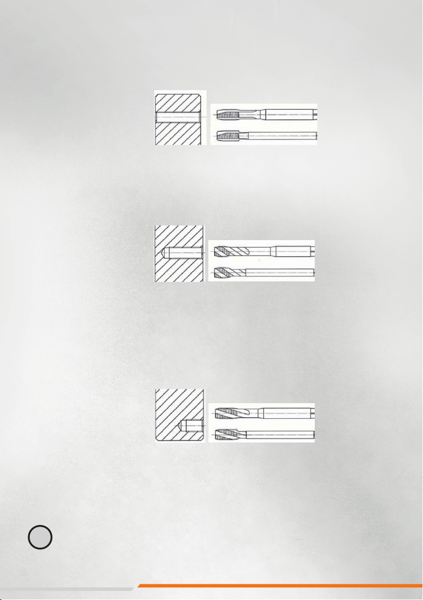
1. Durchgangsloch
Für Durchgangslöcher
empfehlen wir nebenstehende
Gewindebohrer, die die Späne
sicher in Schnittrichtung aus der
Bohrung befördern. Der spezielle
Anschli gewährt auch wieder
ein sicheres Einfädeln, wenn
der Gewinde- bohrer aus der
Gewindebohrung ausgetreten
ist und im Linkslauf zurückfährt.
2. Sacklochbohrungen
Für Sacklochbohrungen
empfehlen wir nebenstehende
Gewindebohrer. Die Späne werden
entgegen der Schnitt- richtung
aus der Bohrung geführt. Es ist
besonders darauf zu achten, daß
der Gewindebohrer nicht auf
Grund aufläuft, da sonst der
automatische Rücklauf nicht
mehr aktiviert werden kann.
Eine entsprechend größere
Vorbohrtiefe muss eingeplant
werden.
Bei Nichtbeachten muss der
Gewindebohrer von Hand gelöst
werden.
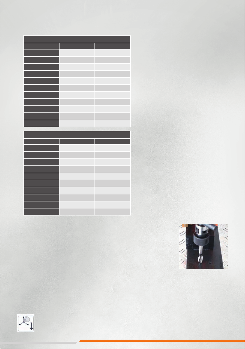
3. Grundlöcher bis 1,5 x D
Dafür eignen sich unsere
Gewinde- bohrer gemäß
nebenstehender Abbildung.
Auch hier werden die Späne
entgegen der Schnittrichtung
aus der Bohrung abgeführt.
Auch hier ist darauf zu achten,
daß der Gewindebohrer nicht
auf Grund aufläuft.
Eine entsprechend größere
Vorbohrtiefe muss berücksichtigt
werden.
Bei Nichtbeachtung muss der
Gewindebohrer von Hand gelöst
werden.
Späneauswurf nach unten
durch die Bohrung DIN 371 mit verstärk-
temSchaft Form B,
mit Schälanschnitt,
3,5 bis 5 Gänge
Toleranz nach ISO 2 6H
DIN 376 mit
Überlaufschaft
Gewindetiefe 3 x D
Späneauswurf am
Werkzeug entlang
DIN 371 mit
verstärktem Schaft
spiralgenutet,
ca. 35° Rechtsdrall
Anschnittform C,
ca. 3 Gänge
DIN 376 mit
Überlaufschaft
Gewindetiefe 2,5 x D
Späneauswurf am
Werkzeug entlang
DIN 371 mit
verstärktem Schaft
spiralgenutet,
ca. 17° Rechtsdrall,
Anschnitt C,
ca. 2 bis 3 Gänge
DIN 376 mit
Überlaufschaft
Gewindetiefe 1,5 x D
Neben unseren Gewindebohrern mit verstärktem Schaft sind natürlich auch Gewindebohrer
nach DIN 376 mit Überlaufschaft einsetzbar.