AlfrescoPlus BBQ MODULE User manual

BBQ MODULE
(ALL SIZES)
ASSEMBLY
INSTRUCTIONS
For further instruction, please visit:
www.alfrescoplus.com.au
04014 12/19
BBQMODULE(ALLSIZES)
INSTRUCTIONS
ASSEMBLYMANUAL

2 | ALFRESCOPLUS™
WARNING! – THIS IS A PERMANENT
CONNECTION SYSTEM!
WHAT’S NEEDED?
Tools Required:
• Soft Sided Hammer (Not Included)
• Philips head screwdriver (Not Included)
• Allen Keys x 2 (Included)
• 50mm Diameter Hole saw or Jigsaw
WHAT’S IN THE BOX?
Box 1 of 3 = BBQ Airframe
Box 2 of 3 = MODULE Panels & Frames
Box 3 of 3 = MODULE Doors
PARTS INCLUDED:
PRE-ASSEMBLED CABINET PANELS x 3
BACK, TOP & BOTTOM x 6
DOORS
• BBQ Small & Medium x 2
• BBQ Large x 4
PLINTH Feet x 8
HARDWARE
• Included Bolt Pack
Essential TIP: Ensure you have a stable flat surface or workbench to
work from. The most ideal height to assemble the module is waist height.
Theworkbench should be at least 1.8m (W) x 1m (H) x 0.7m (D) in size.

BBQ MODULE (ALL SIZES) ASSEMBLY INSTRUCTIONS | 3
LAYOUTDIAGRAM
EssentialTIP:Ensureyouhaveastableflatsurfaceorworkbenchtoworkfrom.Themostidealheighttoassemblethemodule
iswaistheight.Theworkbenchshouldbeatleast1.8m(W)x1m(H)x0.7m(D)insize.
FIG1
FIG. 1
LAYOUT DIAGRAM

4 | ALFRESCOPLUS™
ASSEMBLING SIDE & CENTRE WALLS
AssemblingSideandCentreWalls
FIG5
FIG6
FIG2
FIG3
FIG4
AssemblingSideandCentreWalls
FIG5
FIG6
FIG2
FIG3
FIG4
FIG. 2 FIG. 3
AssemblingSideandCentreWalls
FIG5
FIG6
FIG2
FIG3
FIG4
FIG. 4
AssemblingSideandCentreWalls
FIG5
FIG6
FIG2
FIG3
FIG4
AssemblingSideandCentreWalls
FIG5
FIG6
FIG2
FIG3
FIG4
FIG. 5 FIG. 6

FIG8
FIG9
FIG7
FIG8
FIG9
FIG7
FIG. 8
FIG. 7
FIG. 9
FIG8
FIG9
FIG7
BBQ MODULE (ALL SIZES) ASSEMBLY INSTRUCTIONS | 5

6 | ALFRESCOPLUS™
NoAllocatingholesareusedforplinthfeetsincetheinsideframeedgeprovidestheguide.PlacePlinthfootintocornerof
cabinetframe.Screwdownwithscrewsprovided.Ifeasier,removeplinthshaftfrombaseplatethenscrewdownbase
platefirst.Ifdesiredmovethefronttwoplinthfeetfurtherbacktocreateadeeperkick-plateposition.
FIG10
FIG11
AssemblingPlinthFeetandKickerPlate
ASSEMBLING PLINTH FEET & KICKER PLATE
No Allocating holes are used for plinth feet since the inside frame edge provides the guide.
Place Plinth foot into corner of cabinet frame. Screw down with screws provided. If easier,
remove plinth shaft from baseplate then screw down base plate first. If desired move the
front two plinth feet further back to create a deeper kick-plate position.
FIG. 10
FIG. 11
PleasetakenotethattheKickplateprovidedisreversible,therebygivingyouthechoicebetweenablack“shadowline”
finishorstylishsilverfinish.TheKickplateBiscuitisusedtoconnectontomorethanonecabinet,therebyaligningthekick
plate.
AttachingtheKickPlate
FIG13
FIG12
FIG14

BBQ MODULE (ALL SIZES) ASSEMBLY INSTRUCTIONS | 7
PleasetakenotethattheKickplateprovidedisreversible,therebygivingyouthechoicebetweenablack“shadowline”
finishorstylishsilverfinish.TheKickplateBiscuitisusedtoconnectontomorethanonecabinet,therebyaligningthekick
plate.
AttachingtheKickPlate
FIG13
FIG12
FIG14
ATTACHING THE KICK PLATE
Please take note that the Kick plate provided is reversible, thereby giving you the choice
between a black “shadow line” finish or stylish silver finish. The Kick plate Biscuit is used to
connect onto more than one cabinet, thereby aligning the kick plate.
FIG. 12
FIG. 13 FIG. 14

8 | ALFRESCOPLUS™
FIG15
FIG. 15
Choose the desired color face
of kick plate. (Silver or Black).
No pre drilled holes are possible
due to this color choice. Self
tapping screws are provided to
attach the spring clip plate to
the kick panel. The dimensions
on Fig. 13 can be used as a
guide only since the position of
the plinth foot and the desired
depth of the kick plate will
vary depending on the choice of
plinth foot installation position by
the end user.
ASSEMBLING DOOR & HINGES
• To attach the hinge plate use a standard or power Phillips head
screw driver. The allocating holes are pre drilled into the frame.
• Attach all four-hinge plates when attaching two doors. Attach
the two-left hinge plates when attaching a single door.
FIG. 16
Attach provided Hinge Plate x 4
and self tapping screws.

BBQ MODULE (ALL SIZES) ASSEMBLY INSTRUCTIONS | 9
Illustration on attaching hinges to door panels by using the self-tapping
screws provided.
FIG. 17
Each door hinge includes a
spacing bracket
Place the spacing bracket
on the underside of
the door hinge before
assembly
Screw the door hinge to
the door panel with the
bracket in place as shown

10 | ALFRESCOPLUS™
* Detailed INSTRUCTIONS on how to clip on the doors using clip-on-hinges.
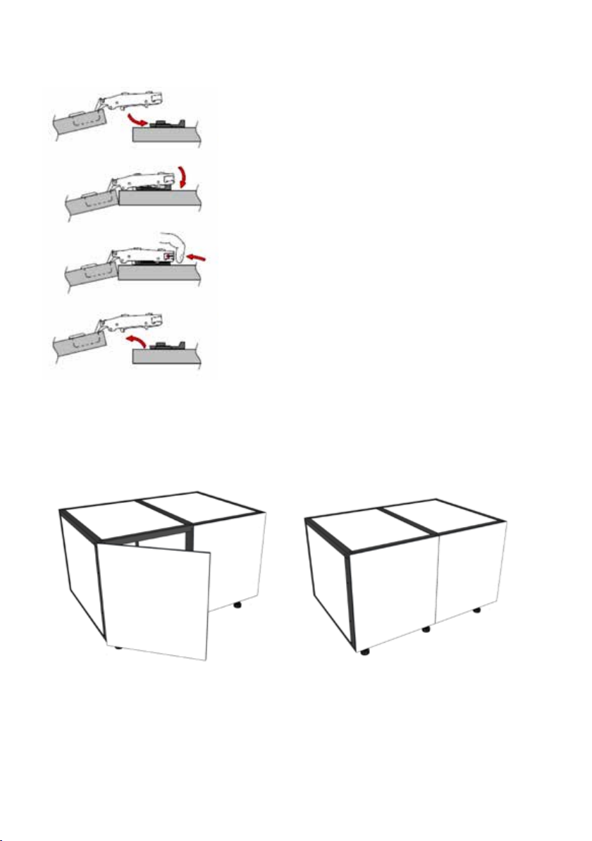
Clamp hinge on to the mounting plate as
shown by direction arrow
Press down the hinge arm to lock the plate
as shown
The door can be quickly removed by
pushing the button
Unclipping the door from the mounting
plate leaves all adjustments unaltered
Firstly align the front hinge section with the front section of the hinge-plate, then press on
the back of the hinge-plate, an audible “Click” should be heard if the door has been correctly
hanged. Repeat the process to secure the bottom hinge and door.
Clip On Hinge Instructions:
*DetailedINSTRUCTIONSonhowtocliponthedoorsusingclip-on-hinges.
ForFurtherinstructionondooradjustmentandlevelingpleasevisit:_____________________________________
Firstlyalignthefronthingesectionwiththefrontsectionofthehinge-plate,thenpressonthebackofthehinge-plate,an
audible“Click”shouldbeheardifthedoorhasbeencorrectlyhanged.Repeattheprocesstosecurethebottomhingeand
door.
Atthisstageyourprogressshouldlooklikethe
aboveimage.Chooseanyseparatestyleofdoor
handleandfitaccordingtothemanufacturers
instructions.
Thedoorshouldfullyopenandcloseasnormal.
FIG18
FIG19
FIG. 18 FIG. 19
The door should fully open and close
as normal.
At this stage your progress should look
like the above image. Choose any separate
style of door handle and fit according to the
manufacturers.
*DetailedINSTRUCTIONSonhowtocliponthedoorsusingclip-on-hinges.
ForFurtherinstructionondooradjustmentandlevelingpleasevisit:_____________________________________
Firstlyalignthefronthingesectionwiththefrontsectionofthehinge-plate,thenpressonthebackofthehinge-plate,an
audible“Click”shouldbeheardifthedoorhasbeencorrectlyhanged.Repeattheprocesstosecurethebottomhingeand
door.
Atthisstageyourprogressshouldlooklikethe
aboveimage.Chooseanyseparatestyleofdoor
handleandfitaccordingtothemanufacturers
instructions.
Thedoorshouldfullyopenandcloseasnormal.
FIG18
FIG19
For further instruction on door adjustment and leveling please visit: www.alfrescoplus.com.au
Positionmodulesinthedesiredconfigurations.Leveleachmoduleandensuretheheightsarecorrectsothatjoiningholes
lineup.Nowjointhetwomoduleswiththebarrelboltssupplied.DoNotovertightenbarrelbolts.PositionandLevelthe
wholeassemblyinfinalposition.(ViewImage33,34,35,36,37,38,39and40)
FIG20
FIG21
FIG22
AttachingandLevelingtheMODULES
Makesurethecabinetsareleveledandaligned,readytobeconnectedbybarrelbolts.Pleasenotethebiscuit
insertedintothekickplateprovided,ensurethekickplateisalignedreadytobeconnected.

BBQ MODULE (ALL SIZES) ASSEMBLY INSTRUCTIONS | 11
Positionmodulesinthedesiredconfigurations.Leveleachmoduleandensuretheheightsarecorrectsothatjoiningholes
lineup.Nowjointhetwomoduleswiththebarrelboltssupplied.DoNotovertightenbarrelbolts.PositionandLevelthe
wholeassemblyinfinalposition.(ViewImage33,34,35,36,37,38,39and40)
FIG20
FIG21
FIG22
AttachingandLevelingtheMODULES
Makesurethecabinetsareleveledandaligned,readytobeconnectedbybarrelbolts.Pleasenotethebiscuit
insertedintothekickplateprovided,ensurethekickplateisalignedreadytobeconnected.
ATTACHING & LEVELING THE MODULES
Position modules in the desired configurations. Level each module and ensure the heights are
correct so that joining holes line up. Now join the two modules with the barrel bolts supplied.
Do Not over tighten barrel bolts. Position and Level the whole assembly in final position (View
FIG. 20,21,22,23,24,25,26 and 27).
FIG. 20
FIG. 21
Make sure the cabinets are leveled and aligned, ready to be
connected by barrel bolts. Please note the biscuit inserted
into the kick plate provided, ensure the kick plate is aligned
ready to be connected.
FIG. 22
Positionmodulesinthedesiredconfigurations.Leveleachmoduleandensuretheheightsarecorrectsothatjoiningholes
lineup.Nowjointhetwomoduleswiththebarrelboltssupplied.DoNotovertightenbarrelbolts.PositionandLevelthe
wholeassemblyinfinalposition.(ViewImage33,34,35,36,37,38,39and40)
FIG20
FIG21
FIG22
AttachingandLevelingtheMODULES
Makesurethecabinetsareleveledandaligned,readytobeconnectedbybarrelbolts.Pleasenotethebiscuit
insertedintothekickplateprovided,ensurethekickplateisalignedreadytobeconnected.

12 | ALFRESCOPLUS™
FIG23
FIG24
DiagramusingtheAllenkeyprovidedtofastencabinetsusingthebarrelbolts.
Insertthe“biscuit”connection
partintotheslotthatisprecut.If
required,gentlytapintoplace
withsoftsidedhammer.
JoiningtheCabinetwithBarrelBolts
CabinetJoinedwithBarrelBolts
FIG23
FIG24
DiagramusingtheAllenkeyprovidedtofastencabinetsusingthebarrelbolts.
Insertthe“biscuit”connection
partintotheslotthatisprecut.If
required,gentlytapintoplace
withsoftsidedhammer.
JoiningtheCabinetwithBarrelBolts
CabinetJoinedwithBarrelBolts
Insert the “biscuit” connection
part into the slot that is pre
cut. If required, gently tap into
place with soft sided hammer.
FIG. 23
Joining the Cabinet with Barrel Bolts Cabinet Joined with Barrel Bolts
FIG. 24
Diagram using the Allen key provided to fasten cabinets using the barrel bolts.

BBQ MODULE (ALL SIZES) ASSEMBLY INSTRUCTIONS | 13
FIG. 25 FIG. 26
FIG. 27
Note: The door is not shown in some images to illustrate the cabinet connection method
more clearly.
Diagram38,39and40illustratesthecabinetsandkickplatealignedandjoined.
Notethatthedoorisnotshowninsomeimagestoillustratethecabinetconnectionmethodmoreclearly.
FIG26
FIG25
FIG27
Figures 25, 26 and 27 illustrate the cabinets and kick plate aligned and joined.
Diagram38,39and40illustratesthecabinetsandkickplatealignedandjoined.
Notethatthedoorisnotshowninsomeimagestoillustratethecabinetconnectionmethodmoreclearly.
FIG26
FIG25
FIG27
Diagram38,39and40illustratesthecabinetsandkickplatealignedandjoined.
Notethatthedoorisnotshowninsomeimagestoillustratethecabinetconnectionmethodmoreclearly.
FIG26
FIG25
FIG27

14 | ALFRESCOPLUS™
ASSEMBLING THE AIRFRAME HEAT-SHIELD
Insert the pre-assembled vertical side shields onto the horizontal bottom heat shields by pressing
firmly into pre inserted prongs. The infill panel should still remain loose at this point.
Insertthepre-assembledverticalsideshieldsontothehorizontalbottomheatshieldsbypressingfirmlyintopreinserted
prongs.Theinfillpanelshouldstillremainlooseatthispoint.
Aftertheheatshieldleftandrighthandsidehavebeenassembledyourairframeshouldresemblethediagrambelow.
AssemblingtheAirframeHeat-shield
ThePronginthehorizontalheat
shieldwillfitintotheframefirmly,
howevercanberemovedagain.
FIG28
FIG29
After the heat shield left and right hand side have been assembled your airframe should
resemble the diagram below.
FIG. 29
Insertthepre-assembledverticalsideshieldsontothehorizontalbottomheatshieldsbypressingfirmlyintopreinserted
prongs.Theinfillpanelshouldstillremainlooseatthispoint.
Aftertheheatshieldleftandrighthandsidehavebeenassembledyourairframeshouldresemblethediagrambelow.
AssemblingtheAirframeHeat-shield
ThePronginthehorizontalheat
shieldwillfitintotheframefirmly,
howevercanberemovedagain.
FIG28
FIG29
Note: The Prong in the horizontal heat shield will fit
into the frame firmly, however can be removed again.
FIG. 28

BBQ MODULE (ALL SIZES) ASSEMBLY INSTRUCTIONS | 15
Gently place the airframe heat shields on top of the BBQ Module. Please note there are
no joining bolts or screws required to fit into place. The airframe will be firmly attached by
making use of the barrel bolts provided, to join to the cabinets or end panels directly adjacent
to the airframe.
Attachthejoiningscrewboltthroughthepre-drilledholesprovided.Makeuseoftheallenkeysprovided.Donot
overtighten.
FIG31
FIG32
Step1:Insertshoulderscrewshalfway
Step2:LowerInfillPanelontoShoulderScrewsandtighten.(Donotovertighten)
FIG33
FIG34
FIG35
FIG. 31
GentlyplacetheairframeheatshieldsontopoftheBBQModule.Pleasenotetherearenojoiningboltsorscrewsrequired
tofitintoplace.Theairframewillbefirmlyattachedbymakinguseofthebarrelboltsprovided,tojointothecabinetsor
endpanelsdirectlyadjacenttotheairframe.
FIG30
FIG. 30

16 | ALFRESCOPLUS™
Attach the joining screw bolt through the pre-drilled holes provided. Make use of the Allen
keys provided. Do not over tighten.
FIG. 32 FIG. 33
Step 1: Insert shoulder screws halfway.
Attachthejoiningscrewboltthroughthepre-drilledholesprovided.Makeuseoftheallenkeysprovided.Donot
overtighten.
FIG31
FIG32
Step1:Insertshoulderscrewshalfway
Step2:LowerInfillPanelontoShoulderScrewsandtighten.(Donotovertighten)
FIG33
FIG34
FIG35
Attachthejoiningscrewboltthroughthepre-drilledholesprovided.Makeuseoftheallenkeysprovided.Donot
overtighten.
FIG31
FIG32
Step1:Insertshoulderscrewshalfway
Step2:LowerInfillPanelontoShoulderScrewsandtighten.(Donotovertighten)
FIG33
FIG34
FIG35
FIG. 34 FIG. 35
Step 2: Lower Infill Panel onto Shoulder Screws and tighten (Do not over tighten).
Attachthejoiningscrewboltthroughthepre-drilledholesprovided.Makeuseoftheallenkeysprovided.Donot
overtighten.
FIG31
FIG32
Step1:Insertshoulderscrewshalfway
Step2:LowerInfillPanelontoShoulderScrewsandtighten.(Donotovertighten)
FIG33
FIG34
FIG35
Attachthejoiningscrewboltthroughthepre-drilledholesprovided.Makeuseoftheallenkeysprovided.Donot
overtighten.
FIG31
FIG32
Step1:Insertshoulderscrewshalfway
Step2:LowerInfillPanelontoShoulderScrewsandtighten.(Donotovertighten)
FIG33
FIG34
FIG35

BBQ MODULE (ALL SIZES) ASSEMBLY INSTRUCTIONS | 17
Your progress should resemble
FIG. 36 at this point.
FIG. 36
Yourprogressshouldresemblethebelowdiagram36atthispoint.
FIG36
TheBBQmoduleandAirframeheatshieldisnowassembledandreadytobejoinedwithothermodules.Pleaserefer
tothemoredetailedinstructionslabeled“Attachingandlevelingthemodules”.
TheBBQmodulecanbealignedandjoinedwiththebarrelboltsprovided.
FIG37
FIG38
Yourprogressshouldresemblethebelowdiagram36atthispoint.
FIG36
TheBBQmoduleandAirframeheatshieldisnowassembledandreadytobejoinedwithothermodules.Pleaserefer
tothemoredetailedinstructionslabeled“Attachingandlevelingthemodules”.
TheBBQmodulecanbealignedandjoinedwiththebarrelboltsprovided.
FIG37
FIG38
The BBQ module and Airframe heat shield is now assembled and ready
to be joined with other modules. Please refer to the more detailed
instructions labeled “Attaching and leveling the modules”.
FIG. 37
The BBQ module can be aligned and joined with the barrel bolts provided.
Yourprogressshouldresemblethebelowdiagram36atthispoint.
FIG36
TheBBQmoduleandAirframeheatshieldisnowassembledandreadytobejoinedwithothermodules.Pleaserefer
tothemoredetailedinstructionslabeled“Attachingandlevelingthemodules”.
TheBBQmodulecanbealignedandjoinedwiththebarrelboltsprovided.
FIG37
FIG38
FIG. 38

18 | ALFRESCOPLUS™
ASSEMBLING & ATTACHING THE END PANELS
Remove the panel and frame from the carton and choose which side of the panel needs to
face towards the outside which should be the same color as the doors chosen (The panel is
reversible depending on color chosen).
FIG. 39
Removethepanelandframefromthecartonandchoosewhichsideofthepanelneedstofacetowardstheoutsidewhich
shouldbethesamecolorasthedoorschosen.(Thepanelisreversibledependingoncolorchosen)
AssemblingandAttachingtheEndPanels
FIG39
EndPanelAttachmentPlate
FIG40
End Panel Attachment Plate

BBQ MODULE (ALL SIZES) ASSEMBLY INSTRUCTIONS | 19
FIG. 40 FIG. 41
Remove the four Small screws from the
Aluminum frame surrounding the stone
top.
Take long screws and align the end panel
frame and module, screw into stone top
frame to anchor the end panel.
FIG. 42
Ensure screws are flush with the frame after screwed into place.
FIG41
FIG42
Ensurescrewsareflushwiththeframeafterscrewedintoplace.
Takelongscrewsandaligntheendpanelframeand
module,screwintostonetopframetoanchortheend
panel.
RemovethefourSmallscrewsfromtheAluminumframe
surroundingthestonetop.
FIG43
FIG41
FIG42
Ensurescrewsareflushwiththeframeafterscrewedintoplace.
Takelongscrewsandaligntheendpanelframeand
module,screwintostonetopframetoanchortheend
panel.
RemovethefourSmallscrewsfromtheAluminumframe
surroundingthestonetop.
FIG43

20 | ALFRESCOPLUS™
Align,InsertandTightentheBarrelBolts
withtheAlenkeyProvided.
PleasenotethebarrelboltsalignedwiththeEndPanelAttachmentPlate.
PleaseNotetherearetwoBarrelBoltsthat
needstobeinsertedandtightened,frontand
back.
FIG44
FIG45
FIG46
FIG. 43
FIG. 44 FIG. 45
Align, Insert and Tighten the Barrel Bolts
with the Allen key Provided.
Please Note there are two Barrel Bolts that
needs to be inserted and tightened, front and
back.
Please note the barrel bolts aligned with the End Panel Attachment Plate.
Table of contents
Other AlfrescoPlus Indoor Furnishing manuals
Popular Indoor Furnishing manuals by other brands

Wholesale Interiors
Wholesale Interiors MARIANA BUNK BED Assembly instructions

Lomado
Lomado Relita STEFAN bunk bed Assembly instructions

KMART
KMART 43333752 ISLA Assembly instructions

Floyd
Floyd Jarvis manual

Workzone
Workzone ASPECT BC1800 Assembly & instruction manual

Mocka
Mocka Hamptons Assembly instructions