Manual
ASC3
Page 6
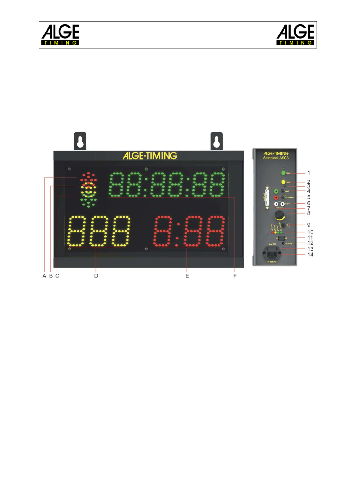
1.1 Connections and Devices
1.1.1 Green Push Button PB1 (1)
The green push button (1) is a manual start button. If you press this button it triggers a start
impulse (same as getting a start impulse from start input (4)). Furthermore, the green push
button is used for settings. You can change the blinking parameters.
1.1.2 Yellow Push Button PB2 (2)
The yellow push button (2) is to select the countdown time. If you press the yellow push but-
ton during the standard operation it allows you to change the interval time. Furthermore, the
yellow push button is used to confirm parameters and move to other parameters.
1.1.3 Program Push Button (3)
If you press this push button (3) and keep it pressed when switching the ASC3 on (on-off
switch 11), the ASC3 switches to programming mode so you can upload new software via
RS232 interface. The switch is hidden inside the case and you will need a tool to press it
(e.g. use a pen).
1.1.4 Start Input (4) - Green-Black Banana Socket
You can connect a start device at this input channel (e.g. startgate or photocell). It stores the
start time and the led/leg time for the start. This time can be shown on the time of day dis-
play, printed on a printer or sent to a PC via RS232.
Furthermore, this input channel is used for the synchronization with another device. It re-
ceives an external impulse for synchronization or, if you press the green push button for syn-
chronization, it also outputs an impulse via this socket to another device.
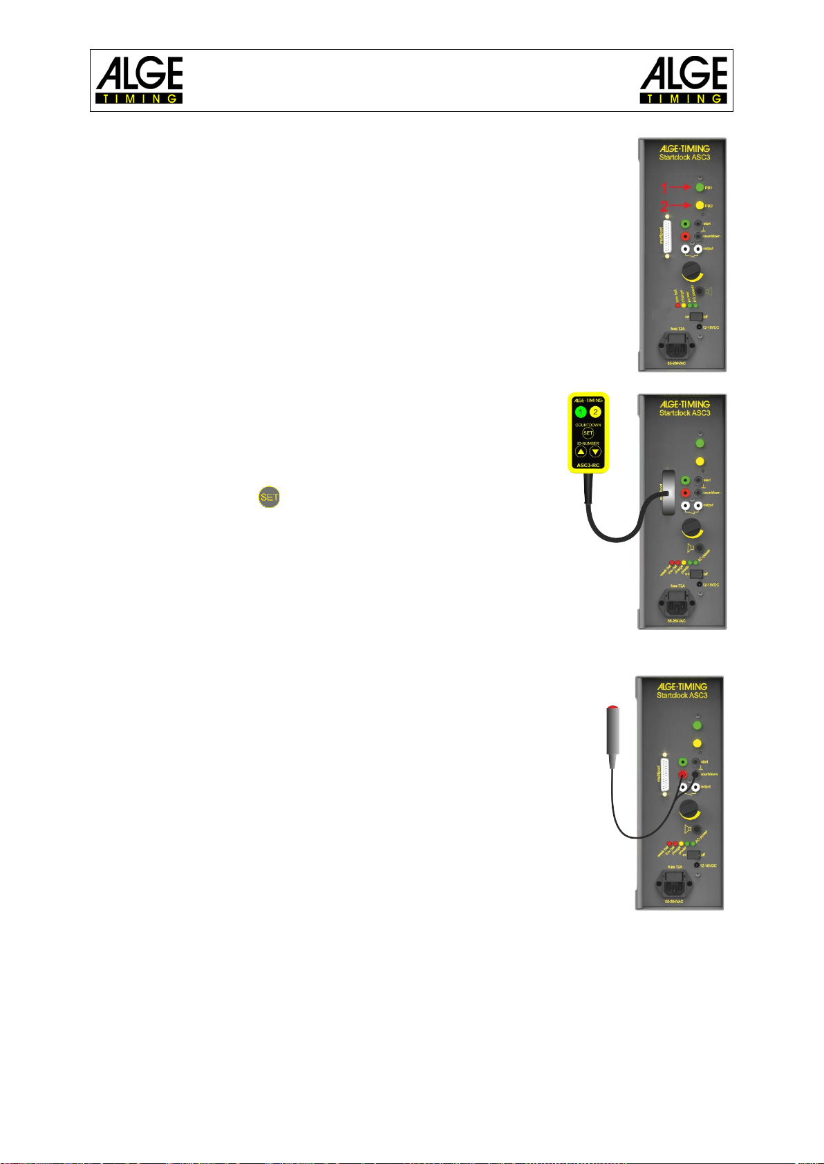
1.1.5 Contact for Countdown Interval Setting (5)
At this red and black banana socket (5), you can connect a push button. With this push but-
ton you can change the countdown interval. If you use the manual countdown, this push but-
ton starts the manual countdown.
Countdown Interval Setting:
•Press the push button for 3 seconds - the time of day disappears from display (F).
•Cd# (# = number from 0 to 9) is shown. The number is blinking.
•In the countdown display (D) the set countdown time is shown.
•Press the push button (short) to change the selected countdown time.
•To confirm the new countdown time, press the push button for 3 seconds and the start-
clock returns to countdown mode with the new start interval.
1.1.6 Start Output (6)
This connection sends an output impulse at the zero signal of the start interval. This impulse
can be used e.g. to start or synchronize another timing device (start impulse).
1.1.7 Power LED (10)
The power LEDs are red, yellow, green and green. The LEDs show the following status
•Red .......................low battery, device will switch off soon
•Yellow ....................charging (external supply is connected)
•Green (left).............power is on
•Green (right)...........AC-power supply
1.1.8 ON-OFF Switch (11)
This switch is to turn the startclock on or off.