Aliaxis IPEX RadonX User manual

SOIL GAS VENTING SYSTEM
FOR LOW-RISE CONSTRUCTION
TECHNICAL MANUAL AND
INSTALLATION METHODS GUIDE
Peace of Mind from the Ground UpTM

©2020 by IPEX. All Rights reserved. No part of this book may be used or reproduced in any manner
whatsoever without prior written permission. For information contact: IPEX Inc., 1425 North Service Road
East, Unit 3, Oakville, Ontario, Canada, L6H 1A7
IPEX Inc. hereinafter referred to as "IPEX".
RadonXTM and Peace of Mind from the Ground UpTM are trademarks used under license.
LITERATURE & WEBSITE DISCLAIMER
The information contained here within is based on current information and product design at the time
of publication and is subject to change without notification. IPEX does not guarantee or warranty the
accuracy, suitability for particular applications, or results to be obtained therefrom. Always consult
a licensed piping-design engineering firm for engineering recommendations during the design and
installation of a project.

Table of Contents
Section A: General Information
RadonXTM Safety Alerts........................................................1
Supplemental Information – DO’S and DON’TS
...2
Product Application..............................................................3
Limits of Use and Application .......................................3
Technical Specification Summary Sheet ............. 4
Soil Gas Venting Basics .....................................................5
Section B: Technical Manual
Material Description .............................................................9
Product Key Dimensions and Weight......................9
Visual Identification.............................................................10
Radon Gas Diffusion Properties of RadonX......10
Thermal Conductivity and Condensation
Consideration Potential....................................................11
Temperature Considerations........................................11
Thermal Expansion...............................................................12
Impact Strength and Pipe Stiffness........................12
Compliance to Standards.............................................12
Section C: Installation Methods Guide
General......................................................................................... 13
Below Grade (Sub-slab) RadonX Piping System
Installation.................................................................................. 13
Alternative Sub-slab Design
Considerations........................................................................15
In Existing Construction.................................................... 16
Above Grade RadonX Piping System
Installation.................................................................................. 16
RadonX Termination Options ...................................... 17
Handling and Storage of RadonX Pipe and
Fittings..........................................................................................20
Handling and Storage of RadonX Cement...... 21
Solvent Welding.................................................................... 22
RadonX Vent Connections to Radon Fan......... 27
Testing of Radon Concentrations........................... 27
Testing Soil Gas Vent Piping....................................... 27
System Repair ........................................................................ 27
Maintenance ........................................................................... 27
Training........................................................................................ 27
Section D: General Terms and Conditions
of Sale
General........................................................................................ 28
Peace of Mind from the Ground UpTM

Section A: General Information
IT IS IMPORTANT TO READ AND UNDERSTAND THIS GUIDE. IT CONTAINS INFORMATION TO HELP MAINTAIN SAFETY AND
PREVENT PROBLEMS.
Improper installation or use of RadonXTM can result in radon gas leak, personal injury and/or property damage. It is
important to be aware of and recognize safety alert messages as they appear in this manual.
The types of safety alert messages are described below.
This is the safety alert symbol. It is used to alert you to potential
personal injury hazards. Obey all safety messages that follow this
symbol to avoid personal injury or death.
“WARNING” Indicates a hazardous
situation which, if not avoided, could
result in severe injury or death.
WARNING
“CAUTION” Indicates a hazardous
situation which, if not avoided, could
result in minor or moderate injury.
“NOTE” signifies special instructions
which are important but are not
related to hazards.
CAUTION
“NOTICE” Indicates a hazardous
situation which, if not avoided,
could result in system failure and
property damage.
NOTICE

RadonXTM Technical Manual and Installation Methods Guide 1
READ & UNDERSTAND the instruction
manual and safety messages before
installing a RadonX soil gas venting
piping system.
NOTICE
NEVER use or test RadonX
with compressed air or
other compressed gases.
Use of compressed air
or gas in RadonX pipe
and fittings can result in explosive
failures and cause severe injury or
death.
WARNING
Follow all preparation and installation
procedures.
For ease of identification, RadonX pipe
and fittings are grey in colour with
yellow markings and warning labels.
DO NOT ALTER or DISCONNECT any of
these components.
RadonX is a PVC piping system to
be used in soil gas depressurization
systems to reduce indoor radon
concentrations. Once the building
is occupied, continued radon
concentration measurements shall
be performed. Consult the C-NRPP,
National Radon Proficiency Program at
c-nrpp.ca for details as to frequency
and guidelines to follow.
Long term exposure to
radon gas can cause
lung cancer.
Test for indoor radon
levels. If measured radon
gas concentrations
exceed the Canadian guideline level,
contact a mitigation professional
certified by C-NRPP, National Radon
Proficiency Program.
WARNING
Rn
Rn
Rn
Rn
Rn
Rn
Rn
Rn
Rn Rn
Rn
Rn
Rn
Rn Rn
Rn
Rn
RadonX Safety Alerts
WARNING
WARNING
WARNING

RadonXTM Technical Manual and Installation Methods Guide2
Supplemental information – DO’S and DON’TS
Refer to the contents of this guide for complete
instructions and guidelines.
CAUTION
DO’S
• Follow recommended safe work practices
• Always adhere to local jobsite and work place safety
regulations
• Contact Local Building Officials about restrictions and
installation inspection in your area
• Keep pipe and fittings clean and in original packaging until
needed
• If pipe and fittings are stored outdoors, cover with a well
ventilated white tarp and never store other products on
top of pipe
• Follow handling and storage procedures found in this guide
• Only use tools on RadonX pipe and fittings as described in
this guide
• Cut the pipe ends squarely
• Deburr and bevel the pipe end with a chamfering tool
before solvent welding
• Slowly rotate the pipe a quarter turn when inserting pipe in
fitting socket when solvent welding
• Follow RadonX recommended set times found in this guide
before commissioning the vent system
• Avoid puddling of solvent cement in fittings and pipe
• Ensure excess solvent cement and primer does not run
inside pipe and fittings
• Check all joints for proper joint construction
• Allow for movement due to expansion and contraction
• If a radon fan is installed with RadonX pipe and fittings,
read fan manufacturer’s installation instructions carefully
and install product accordingly
DON’TS
• DO NOT mix pipe, fitting or joining methods from
different manufacturers
• DO NOT use RadonX pipe and fittings for any
application other than soil gas venting
• DO NOT use or mix RadonX components with
other IPEX pipe and fittings
• DO NOT use or install perforated RadonX gas
collection pipe above ground
• DO NOT use or install access tee fittings with
RadonX vent pipe
• DO NOT terminate passive vent stacks with a
side-wall discharge near ground level
• DO NOT solvent weld pipe to fans directly
• DO NOT solvent weld rain cap to pipe directly
• DO NOT use solvents or cements other than what
is required by this guide
• DO NOT install adhesive tape in direct contact
with RadonX product
• DO NOT use solvent cement that has exceeded
its shelf life or has become discoloured or jelled
• DO NOT use solvent cement near sources of heat
or open flame, or when smoking
• DO NOT subject vent system to compressed air
• DO NOT cut pipe with dull or broken cutting-tool
blades
• DO NOT use ratchet cutters or reciprocating saw
to cut pipe
• DO NOT use RadonX product that’s been stored
unprotected outdoors and is faded in colour
• DO NOT allow threaded rod to come in contact
with the pipe; for example, threaded rods used to
connect pipe hangers

RadonXTM Technical Manual and Installation Methods Guide 3
Product Application
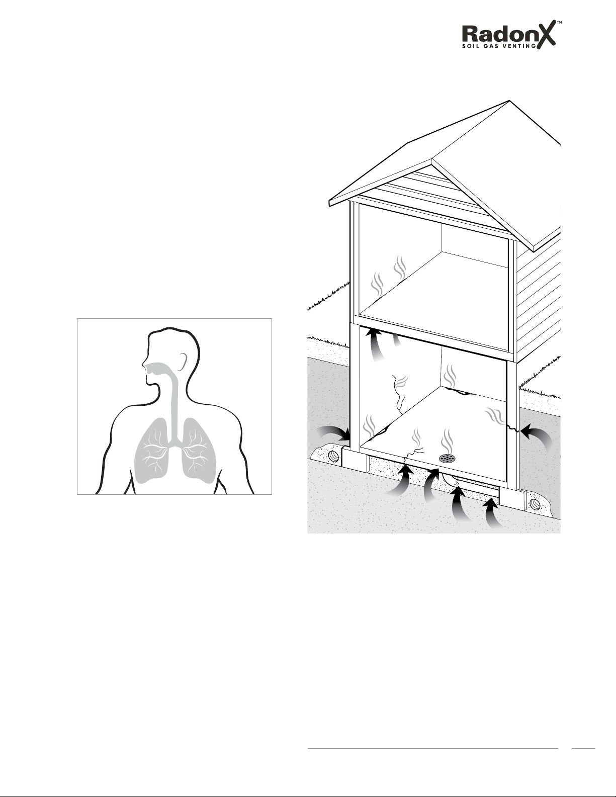
RadonXTM Soil Gas Venting (SGV) Piping System is
intended to vent soil gases and help reduce indoor
radon concentrations in low-rise construction. RadonX
pipe and fittings satisfy the requirements of the National
Building Code 2015.
Limits of Use and Application
(a) RadonX does not treat or cure lung cancer.
(b) All RadonX soil gas venting pipe and fittings must
be carefully examined for possible damage prior
to installation. Any damaged product must be
replaced. No attempt at repairs are to be made at
the job site.
(c) Soil gas venting application will cause the piping
system to expand and contract accordingly. Proper
care must be taken to allow for this movement
through walls, ceilings, and roof penetrations. The
venting system must be supported in accordance
with these instructions.
(d) Use RadonX cement and System 636®primer to
assemble RadonX soil gas venting systems.
(e) Venting should be as direct as possible with a
minimum number of fittings.
(f) Horizontal runs should be minimized.
(g) All horizontal sections of the venting system must be
installed with a slope not less than 1% down towards
the riser in order to collect condensate and remove
condensate generated inside the line. The removal
of condensate will help reduce the possibility of ice
buildup and blockage.
(h) All framing requirements for floor and ceiling
penetrations shall be in accordance with the
local building code and/or the local regulatory
authority. All penetrations of fire rated floors and
walls in multi-unit residential shall be firestopped as
described in the Firestop section of this guide.
(i) Roof penetrations should be sealed with a
plumbing roof boot or equivalent flashing as per
the local building code, or as permitted by the local
regulatory authority.
(j) If spray foam insulation comes in contact with
RadonX, it is recommended that foam be applied in
a maximum layer thickness of 50mm (2 inches) until
the required thickness of insulation is achieved.
(k) Do not use or install perforated RadonX pipe above
ground.
(l) All RadonX piping system in unconditioned space
shall be insulated as described in the Above Grade
RadonX piping system installation section of this
guide.
DO NOT mix pipe, fittings or joining methods from
different manufacturers as they have different joint
systems and adhesives. This can result in unsafe
conditions and cause radon gas leak.
WARNING
DO NOT use or mix RadonX components with other IPEX
pipe and fittings. DO NOT use RadonX in applications
other than soil gas venting. These can result in unsafe
conditions.
WARNING
RadonX is a combustible piping system and as such
will be subjected to all conditions and limitations
of the Building Code for above-ground use in Non-
Combustible (commercial) buildings. For further
information, contact IPEX.
NOTICE
Follow IPEX solvent welding procedures as shown in
this guide, and check for proper joint construction
when joining pipe to fittings.
NOTICE
RadonX is a PVC piping system to be used in soil gas
depressurization systems to reduce indoor radon
concentrations. Once the building is occupied,
continued radon concentration measurements shall
be performed. Consult the C-NRPP, National Radon
Proficiency Program at c-nrpp.ca for details as to
frequency and guidelines to follow. If measured
radon gas concentrations exceed the Canadian
guideline level, contact a mitigation professional
certified by a C-NRPP.
WARNING

RadonXTM Technical Manual and Installation Methods Guide4
General – RadonX™ soil gas venting, engineered by IPEX Inc., is a complete Schedule
40 PVC piping system that addresses the need for venting soil gases from low-
rise dwellings. When installed properly, RadonX can help reduce indoor radon
concentrations. RadonX offers a full range of vent pipes, gas collection pipes, fittings
and solvent cement.
Materials – RadonX PVC pipes and fittings are manufactured from compounds that
comply with the material requirements of CSA B181.2 “PVC Drain, Waste and Vent Pipe
and Pipe Fittings”.
Compliance to Standards – RadonX pipe and fittings comply to all material and testing
requirements of CSA B181.2 and ASTM D2665. RadonX piping system complies to gas
leakage, pull out, torque and combustibility test requirements of ULC S636.
Code compatibility – RadonX pipe and fittings satisfy the requirements of provincial
and National Building Code 2015.
Dimensions – RadonX pipe and fittings are offered in 4” Schedule 40 size and meet the
dimensional requirements of CSA B181.2 and ASTM D2665.
Markings – In accordance with CGSB/CAN 149.11 and CGSB/CAN 149.12, each length
of RadonX pipe is tagged with a warning label. All RadonX fittings are tagged with a
warning label against the risk of radon gas leak if system is not installed as per IPEX
installation instructions. All RadonX pipe and fittings include identification markers to
indicate size, material description, product application, complying standards, date of
production and manufacturer’s name or trademark. The pipe will consist of two yellow
print-lines located 180 degrees apart. All warning labels are in yellow. All product
markings are bilingual.
Cements – RadonX solvent cement meets the performance requirements of ASTM
D2564. PVC cement is in yellow colour and should be only used with RadonX soil gas
venting systems.
Installation – RadonX pipe and fittings are designed and tested as a system by
IPEX Inc. Mixing of pipe, fittings or joining methods from different manufacturers is not
allowed as they have different joint systems and adhesives. These can result in unsafe
conditions and cause radon gas leaks. RadonX pipe and fittings must NOT be used for
any applications other than soil gas venting.
Technical Specification Summary Sheet

RadonXTM Technical Manual and Installation Methods Guide 5
Soil Gas Venting Basics:
What is Radon?
Radon is a colourless, odorless gas that occurs naturally
from the decay of uranium, a natural radioactive
material found in all soil and rock. As radon breaks
down, it forms radioactive particles that can get lodged
into our lungs as we breathe. The energy released by
radon particles can damage lung cells creating lung
cancer. Not everyone exposed to radon gas will develop
lung cancer, and the time between exposure and the
onset of the disease could take many years. This is
why radon gas is known as a silent killer. According to
Health Canada, Radon is the second leading cause of
lung cancer after smoking. More than 3000 people die
from radon-induced lung cancer every year. For more
information on radon, visit takeactiononradon.ca.
Rn Rn
Rn
Rn
Rn
Rn Rn
Rn
Rn
Rn
Rn
Rn
Rn
Rn Rn
Rn
Rn
Rn
Rn
Rn
Rn Rn
Rn Rn
Radon gas can accumulate to dangerous levels inside a
home and become a risk to human health. It can enter
the building through openings in contact with soil such as
cracks in foundation walls/floor slabs and gaps around
service pipes and floor sumps etc. Similar to other gases,
it can diffuse through materials including concrete slabs.

RadonXTM Technical Manual and Installation Methods Guide6
Does Radon Gas exist in all houses?
Almost all houses in Canada have some amount of
radon gas. However, radon concentrations vary from
province to province and from house to house as many
factors affect the final indoor levels. Soil characteristics,
construction type, foundation condition, and the use
of exhaust fans, appliances and windows that affect
the pressure difference between the soil and the house
are the most critical factors. There are no guidelines
which address building site characterization for radon
risk. This is due to the fact that the level of radon in a
completed home or building cannot be predicted prior
to construction. Therefore, the only way to know for sure
is via testing after construction. Radon concentrations
can vary significantly from hour to hour and day to day,
therefore long-term measurements are recommended
while determining radon levels. Radon test kits can be
purchased online at takeactiononradon.ca or be found
at many hardware and building supply stores across
Canada. If the measured radon concentrations exceed
the Canadian guideline level, Health Canada and
National Building Code require that homeowners take
action to reduce the levels. More information on the
most current acceptable radon gas levels can be found
at canada.ca/en/health-canada/services/health-risks-
safety/radiation.
How can Radon gas levels be
reduced with RadonX soil gas
venting?
The most common and effective radon reduction
method is called sub-slab depressurization. This involves
installing a pipe through the foundation floor slab that
draws the radon gas from below the home and releases
it into the outdoors where it is quickly diluted.
In new construction:
In new construction, there are three installation methods
of soil gas vent piping: Level-1 (radon rough-in),
Level-2 (full passive stack) and Level-3 (active stack).
Level-1, capped rough-in stub is not a complete radon
reduction system. It only allows the future addition of a
full passive or active system if the home tests high for
radon after occupancy.
Figure 1:
Level-1: Radon rough-In
RadonX capped
rough-in stub
RadonX perforatedRadonX perforated
gas collection pipegas collection pipe
Peace of Mind from the Ground UpTM

RadonXTM Technical Manual and Installation Methods Guide 7
Indoor radon levels can be reduced by installing a full
passive vent stack (Level-2) that consists of
a perforated pipe below the foundation floor that
collects radon gas; and
a full vent stack that runs upwards throughout the
inside of the building releasing the gas outside above
the roof.
In the majority of cases, the combination of and
is sufficient to lower radon levels to acceptable limits
within the house. It is more practical and economical
to install a passive stack during construction of a new
home. In order to reduce the health risks of radon gas,
IPEX recommends that all new low-rise residential homes
should have a full passive stack.
Many municipalities are being proactive in requiring a full
vent stack (Level-2) for new homes to protect against
potentially harmful radon levels and have dedicated
radon programs for new construction. As a minimum, it is
very critical to install the sub-slab pipe and radon rough-
in stub (Level-1) as per the National Building Code 2015
requirements in the event that future radon mitigation is
required.
If radon levels are still above Health Canada’s
recommended concentrations with a passive stack,
further reduction can be achieved by installing a radon
fan (see Figure 3) to the vent stack converting the
depressurization system into an active one (Level-3).
Figure 2:
Level-2: Full passive stack
RadonX
vent stack
RadonX
exhaust
rain cap
RadonX perforatedRadonX perforated
gas collection pipegas collection pipe
Figure 3:
Level-3: Active stack
OR
RadonX
vent stack
RadonX
exhaust rain
cap
Radon fan
Radon
fan
Wall
exhaust
Vent
RadonX perforatedRadonX perforated
gas collection pipegas collection pipe
1
1
1
2
2
2
Peace of Mind from the Ground UpTM

RadonXTM Technical Manual and Installation Methods Guide8
Figure 4:
Typical full active soil depressurization system for
existing buildings
In existing buildings:
Since it is not practical to install a sub-slab pipe and/
or a full vertical stack after occupancy, the majority of
retrofit applications for soil gas venting are completed
with a radon fan where the piping system is terminated
on a side wall (see Figure 4). These installations are
critical as there are too many factors affecting the
overall efficiency such as the suction point location in
the basement, sealing of the cut openings and code
approved terminations. IPEX recommends that all retrofit
applications for existing homes should be carried out
by a professional who is certified under the Canadian
National Radon Proficiency Program (C-NRPP). Please
visit c-nrpp.ca for more information.
RadonX
vent stack
Radon
fan
Wall
exhaust
Vent
RadonXRadonX
non-perforatednon-perforated
vent stack extendedvent stack extended
below slabbelow slab

RadonXTM Technical Manual and Installation Methods Guide 9
Figure 5:
RadonX Gas Collection Pipe – Perforation Details
Section B: Technical Manual
Material Description:
RadonX Soil Gas Venting (SGV) pipe and fittings are
made of solid Polyvinyl chloride (PVC) to Schedule 40
thickness. PVC is the most frequently specified of all
thermoplastic piping materials and has been used
successfully since the 1940s in many pressure and non-
pressure piping applications. PVC is characterized
by distinctive physical properties and is resistant to
corrosion and chemical attack by acids, alkalis, salt
solutions and many other chemicals.
Product Key Dimensions and Weight:
The physical dimensions and tolerances of RadonX SGV
pipe and fittings meet the requirements of CSA B181.2 and
ASTM D2665. They are made to Schedule40 thickness and
available in 100mm (4 in.) nominal pipe size.
TABLE 2. RADONX SGV PIPE DIMENSIONS AND WEIGHT
Print-line along the pipe
0°
48°
144°
96°
100mm hole spacing
Hole diameter 15mm
RadonX gas collection pipe has a unique perforation
pattern featuring 6 evenly cut holes with a
diameter of 15mm every 100mm of pipe (see Figure
5). Compared to non-perforated or standard
perforated sewer pipe, the perforation pattern in
RadonX gas collection pipe has been proven to
increase the airflow in the vent stack resulting in
more soil gas movement in the sub-slab area as
per research testing conducted at the National
Research Council of Canada (NRC).
NOTE: RadonX gas collection pipe as well as vent pipe are coextruded and made in 10ft lengths without bell-ends.
NOTE: Rain cap is not made to Schedule 40 thickness. It is a roof termination accessory that is mechanically fastened.
Product
Code
Product
Description
Application
Type
Nominal
Pipe Size
(in.)
A
Nominal Pipe
Size (in.)
B
Avg. Inside
Diameter (in.)
C
Min. Wall
Thickness
(in.)
Pipe
Weight
(lb/ft)
181004 Gas collection
pipe
Perforated:
Below ground 4 4.50 3.95 0.24 2.0
181008 Vent pipe
Non-
perforated:
Above ground
4 4.50 3.95 0.24 2.1
A
B
A
C
B
TABLE 1. RADONX SGV FITTINGS DIMENSIONS AND WEIGHT
Product
Code
Product
Description Socket Type
Nominal
Pipe Size
(in.)
A
Min. Socket
Depth (in.)
B
Min. Body Wall
Thickness (in.)
Fitting
Weight
(lbs)
286084 Tee Wye HxHxH
41.75 0.25
2.51
286124 90° Elbow HxH 1.76
286244 45° Elbow HxH 1.12
286254 22 ½° Elbow HxH 0.64
286354 Coupling HxH 0.73
286414 Cap H 0.64
286715 Rain Cap H 1.50 0.15 0.94
A
B
A
C
B

RadonXTM Technical Manual and Installation Methods Guide10
Visual Identification:
There are some differences in appearance between
RadonX and other standard drainage and plumbing
products. RadonX gas collection and vent pipes are grey
in colour and have a continuous dual (180 degree apart)
print-line that is yellow in colour for ease of identification.
As part of the marking requirements of CAN/CGSB 149.11
and CAN/CGSB 149.12, RadonX pipes are tagged with
a yellow warning label every 1.8m (6ft). In addition, all
RadonX fittings are tagged with a yellow warning label
highlighting the risk of a radon gas leak if the system
is not installed as per IPEX installation instructions. The
images below show the position of the warning labels
and close-up information printed on the labels.
All product markings are bilingual.
Radon Gas Diffusion Properties
of RadonX:
Radon diffusion through pipe material can demonstrate
how likely radon gas can diffuse through the wall of
the pipe and into the buildings. This could be even
more critical in basements where radon enriched gas
is trapped in capped rough-in pipe stubs installed for
longer durations (Level-1, see Figure 1, in the section
"Soil Gas Venting Basics" of this manual). The likelihood
of this occurring would depend on radon diffusion
coefficient and thickness of the pipe material. The radon
diffusion coefficient D (m2/s) is a material property that
would vary in every PVC formulation. The higher the
radon diffusion coefficient, the more radon that would
diffuse into the surroundings. Radon resistance (defined
by Jiranek and Svoboda, 2017) is a more accurate
way of evaluating the effectiveness of a material in
reducing or preventing radon entry, especially for
materials of varying thicknesses. Based on the test
results performed by the National Research Council
of Canada (NRC), for Schedule 40 thickness, the 4”
RadonX pipe material has a radon resistance value
of 6.46x10⁹(s/m). This level is considered by NRC to
be suitable for venting soil gas containing radon with
negligible risk of radon diffusing through the wall of
the piping system.
Description Colour
Pipe and fittings Grey
Pipe print-line (dual) Yellow
Pipe labels Yellow
Fitting labels Yellow
Solvent Cement Yellow
Description Value
Radon diffusion coefficient - D (m2/s) 6.02x10⁻¹²
Radon resistance -RRn (s/m) 6.46x10⁹
Figure 6:
RadonX Product Colour Identification
TABLE 3. RADON GAS DIFFUSION PROPERTIES
OF RADONX PIPE

RadonXTM Technical Manual and Installation Methods Guide 11
Thermal Conductivity and
Condensation Potential:
The coefficient of thermal conductivity of RadonX
material is 1.2 BTU•in/(ft2•hr•°F). The high thermal
resistance and Schedule 40 thickness of RadonX greatly
reduce the potential of condensation (also known as
pipe sweating) forming on the surface of the pipe.
However, condensation could still form under certain
conditions. To calculate condensation potential,
the following parameters must be known: soil gas
temperature, indoor air temperature, design relative
humidity and insulation thickness (if any). Using these
input variables, both the pipe surface temperature and
the Dew Point temperature can be calculated. Should
the pipe surface temperature exceed the Dew Point
temperature, condensation will not occur. For reference
TABLE 4. CONDENSATION POTENTIAL OF 4” SCHEDULE 40 RADONX PIPE
Soil Gas Temperature (°C) 10
Relative Humidity 50% 60% 70% 80%
Indoor Air Temperature (°C) 18.3 21.1 23.9 18.3 21.1 23.9 18.3 21.1 23.9 18.3 21.1 23.9
Condensation Forming (Y/N) N N N N N N N Y Y Y Y Y
Soil Gas Temperature (°C) 15
Relative Humidity 50% 60% 70% 80%
Indoor Air Temperature (°C) 18.3 21.1 23.9 18.3 21.1 23.9 18.3 21.1 23.9 18.3 21.1 23.9
Condensation Forming (Y/N) N N N N N N N N N N Y Y
Soil Gas Temperature (°C) 20
Relative Humidity 50% 60% 70% 80%
Indoor Air Temperature (°C) 18.3 21.1 23.9 18.3 21.1 23.9 18.3 21.1 23.9 18.3 21.1 23.9
Condensation Forming (Y/N) N N N N N N N N N N N N
purposes, see below tables of pipe surface temperatures
for RadonX for a given set of relative humidities, soil
gas temperature, ambient air temperature and the
resulting Dew Point temperature. Should the pipe surface
temperature be at or below the Dew Point temperature,
condensation will occur.
Based on these tables, in order to reduce surface
condensation, IPEX recommends homeowners to control
relative humidity levels indoors.
Temperature Considerations:
The temperature of soil gas inside a piping system
typically changes between 10-20°C (50-68°F) throughout
the year depending on the season and dwelling location.
For continuous flow non-pressure applications, RadonX
pipe and fittings can be safely used up to 60°C (140°F).

RadonXTM Technical Manual and Installation Methods Guide12
Thermal Expansion:
As with all construction materials, RadonX piping
undergoes expansion and contraction when subjected
to changes in temperature. It is worthy to note that
RadonX, due to the inherent properties of PVC, would
have a much lower (40%) rate of expansion-contraction
than commonly used plastic ABS DWV pipe.
Impact Strength and Pipe Stiffness:
The impact strength of a material is a measure of its
ability to absorb impact energy without failure. Pipe that
is resistant to impact is not easily damaged or broken,
trimming material costs at the jobsite. The CSA B181.2
standard requires 4” Schedule40 PVC pipe to withstand
the following minimum impacts: 240 Joules at 23°C and
135 Joules at 0°C.
RadonX gas collection and vent pipes meet the
minimum CSA requirement for pipe stiffness of 1700 kPa,
which helps it to resist soil loads and other external
stresses.
Compliance to Standards:
While there is no dedicated piping standard for the
application of soil gas venting, RadonX is tested to and
complies with the following standards:
The tables below show expansion values applicable
to RadonX. The linear expansion is shown for numerous
temperature changes (ΔT) versus various straight-length
runs of pipe. In a typical 12m (40ft) RadonX installation,
considering a maximum ΔT of 10°C (20°F) in soil gas,
the linear expansion (ΔL) due to thermal expansion and
contraction would be 6.5mm (0.29in).
TABLE 5. RADONX LINEAR EXPANSION (ΔL) IN INCHES TABLE 6. RADONX LINEAR EXPANSION (ΔL) IN MM
Temp.
Change
(ΔT°F)
Length of Run in feet
10 20 30 40 50
10 0.04 0.07 0.11 0.14 0.18
20 0.07 0.14 0.22 0.29 0.36
30 0.11 0.22 0.32 0.43 0.54
40 0.14 0.29 0.43 0.58 0.72
50 0.18 0.36 0.54 0.72 0.90
60 0.22 0.43 0.65 0.86 1.08
70 0.25 0.50 0.76 1.01 1.26
80 0.29 0.58 0.86 1.15 1.44
Temp.
Change
(ΔT°C)
Length of Run in meters
3 6 9 12 15
5 0.8 1.6 2.4 3.2 4.1
10 1.6 3.2 4.9 6.5 8.1
15 2.4 4.9 7.3 9.7 12.2
20 3.2 6.5 9.7 13.0 16.2
25 4.1 8.1 12.2 16.2 20.3
30 4.9 9.7 14.6 19.4 24.3
35 5.7 11.3 17.0 22.7 28.4
40 6.5 13.0 19.4 25.9 32.4
Standards RadonX™
Tolerances and
dimensions
CSA B181.2;
ASTM D2665
All material and
testing requirements
CSA B181.2;
ASTM D2665
Gas venting system
performance tests
-Gas leakage
-Pull-out
-Torque
-Combustibility
ULC S636
Cement ASTM D2564
Product Markings CGSB/CAN 149.11;
CGSB/CAN 149.12

RadonXTM Technical Manual and Installation Methods Guide 13
Section C: Installation Methods Guide
General:
A. Examine all components for possible damage prior
to installation.
B. Proper joint assembly is essential for a safe
installation. Follow these instructions exactly as
written. Check the integrity of joints to be leak proof
upon completion of assembly.
C. This venting system must be free to expand and
contract. This venting system must be supported in
accordance with these instructions.
D. Check for proper joint construction when joining pipe
to fittings.
E. Check for unrestricted vent movement through walls,
ceilings, and roof penetrations.
F. DO NOT use or mix RadonX components with other
IPEX products.
Below Grade (Sub-slab) RadonX
Piping System Installation:
In New Construction:
A soil gas collection system shall be provided under all
concrete slabs within the building footprint. Soil gas
collection system consists of a gas permeable layer,
which is clean coarse gravel and a RadonX perforated
soil gas collection pipe.
(a) RadonX perforated soil gas collection pipe shall
extend into the gas-permeable layer (see Figure 7)
and be located near or be oriented in the direction
of the centre of dwelling with the print-line
displaying on top. Other sub-slab gas collection
pipe configurations and recommendations are
shown in the section “Alternative Sub-slab Design
Considerations” of this installation guide.
(b) Clean granular material must be used as gas
permeable layer on the undisturbed soil to a depth
not less than 100mm (4”) and aggregate must
contain no more than 10% of material that will pass a
4mm (5/32”) sieve. The final depth of the gas
permeable layer should be determined as per the
local building code.
G. DO NOT use RadonX in other piping applications such
as drain, waste and vent (DWV) and flue gas venting
(FGV).
H. PRODUCT INSTALLATION AND SOLVENT WELD
TRAINING IS RECOMMENDED.
An efficient gas permeable layer permits radon
reduction system to withdraw soil gas from the entire
sub-slab area. Typical void ratios in the gas permeable
layer are in the range of 35-40% as per ASTM E1465.
NOTICE
Center
of the Slab
Pipe Print-line
Pipe Print-line Face
Top and Bottom
Concrete
Foundation RadonX
Non-perforated
Vent Pipe
Sealant
1 ft
Permanent Cap
Min.
1/2 ft
Min.
Soil
Coarse
Gravel
Perforations
Coarse Gravel
Gas Permeable
Layer
Concrete Floor
Soil
90˚ Elbow RadonX Perforated
Gas Collection Pipe
RadonX Perforated
Gas Collection Pipe
90˚ Elbow
Figure 7:
Typical Installation of RadonX Rough-in
RadonX pipe, fittings and cements are designed and
tested as a system and must be installed as such. Only
products approved by IPEX as part of the RadonX soil gas
venting system must be used. DO NOT mix pipe, fittings
or joining methods from different manufacturers. This can
result in unsafe conditions and cause radon gas leak.
WARNING

RadonXTM Technical Manual and Installation Methods Guide14
(c) For every 46m2of the building footprint, a minimum of
3m (10ft) of RadonX perforated gas collection pipe
shall be used in the sub-slab area.
(d) Each dwelling shall be provided with a separate riser
and soil gas collection system.
(e) RadonX perforated gas collection pipe must be
placed on soil with the print-line displaying on top.
(f) All RadonX pipe installed below ground must have at
least 1% slope towards the end of the pipe so that
any unwanted condensation can drain properly
without any pooling.
(g) Horizontal runs of utility pipe and conduit within the
gas permeable layer shall not interfere with RadonX
perforated gas collection pipe and should preferably
be installed lower than the RadonX perforated gas
collection pipe.
(h) Perimeter drainage pipe around the footings must be
installed lower than the RadonX perforated gas
collection pipe.
(i) RadonX perforated gas collection pipe shall not be
obstructed below slab (e.g. strip footings). If
continuous obstruction(s) exists, install piping through
footing to ensure communication between two sub-
slab areas (see Figure 12).
(j) RadonX perforated gas collection pipe shall be
connected to the riser with a RadonX 90° elbow.
(k) The 90° RadonX elbow shall be installed at least
30cm (1ft) away from the concrete footings
(see Figure 8).
(l) The riser acting as a suction point shall be made of
non-perforated RadonX vent pipe and shall not be
less than 15cm (1/2 ft) above the finished floor slab
(see Figure 7).
(m) If the riser is not located close to the concrete
footing, instead of using a 90° elbow, a RadonX
tee-wye fitting can be installed to connect two
perforated gas collection pipes within one sub-slab
area (see Figure 9).
(n) A RadonX permanent cap shall be solvent welded
onto the riser before pouring concrete.
(o) The RadonX pipe joints on the concrete floor shall be
sealed using a compatible sealant as required by
the local building code.
(p) To avoid leaning of riser during concrete pour, use
4” pipe clamps with two holes (Product codes:
077822 or 077264).
(q) Using standard metal stakes on each hole, position
clamps on a level dirt surface to secure RadonX
perforated soil gas collection pipe onto ground
(see Figure 10), as required. Clamps must be placed
carefully not to interfere with perforations.
RadonX perforated soil gas collection pipe must only
be used in below ground installations. DO NOT use
perforated pipe for above ground installations.
CAUTION
Figure 8:
RadonX sub-slab piping when the riser is not
at the centre Figure 10:
Typical pipe clamp installation
Figure 9:
Acceptable RadonX sub-slab piping when the riser
is at the centre
Min.
1 ft
Centre of the Slab
Gravel not shown Concrete footing
Min.
1 ft
Centre of the Slab
Gravel not shown Concrete footing
Min.
1 ft
Pipe clamps
Metal stake
RadonX perforated
gas collection pipe
RadonX
non-perforated
vent pipe
RadonX capped
rough-in stub
Soil

RadonXTM Technical Manual and Installation Methods Guide 15
Figure 11:
Alternative RadonX gas collection pipe loop in the
sub-slab area
Figure 12:
Connecting two gas permeable layers
Min.
1 ft
Gravel not shown
RadonX
non-perforated
vent pipe
Concrete footing
Min.
1 ft
Min.
1 ft
1
1
RadonX perforated
gas collection pipe
2
2
Gravel not shown
Gravel not shown
RadonX
non-perforated
vent pipe
Concrete footing
Riser
Min.
1 ft
Min.
1 ft
1
1
1
1
RadonX perforated
gas collection pipe
2
2
2
Alternative Sub-slab Design
Considerations:
Extending RadonX perforated gas collection pipe
beyond 3m (10ft) of length in the sub-slab area
could improve the effectiveness of soil gas venting.
Increased airflow in the RadonX vent stack, a more
evenly distributed sub-slab suction and reduced risk of
clogging during service are some of the benefits.
The extension of RadonX perforated gas collection pipe
below ground could be more critical to create a better
stack effect in soil gas piping systems. Therefore, IPEX
recommends installing a pipe loop design around the
perimeter of the footings (see Figure 11).
If a building’s sub-slab area is divided by a
strip footing, one riser could be used to possibly
interconnect the two gas permeable layers
(see Figure 12).

RadonXTM Technical Manual and Installation Methods Guide16
In Existing Construction:
It is not practical to install a complete RadonX soil gas
venting system that includes a sub-slab pipe and/or a
full vertical stack after occupancy. Therefore, the majority
of the retrofit applications for soil gas venting can be
completed with a RadonX non-perforated vent pipe
and a radon fan where the piping system is terminated
on a side wall. In this scenario, the existing concrete
floor should be drilled in order to penetrate the RadonX
vent pipe 5cm (2”) below the slab (see Figure 4 from the
previous section that is also reproduced below).
Above Grade RadonX Piping System
Installation:
(a) RadonX capped rough-in (Level-1), as seen in Figure
1 from the previous section that is also reproduced
below, shall be extended vertically and terminated
outdoors depending on the level of mitigation
(Level-2 or Level-3).
(b) Wherever possible, RadonX vent pipe shall be
installed in vertical direction. If necessary, horizontal
offsets in the vertical stack can be made with
RadonX 22 ½° elbow fittings.
(c) Horizontal runs and use of 90°elbow fittings shall
be minimized.
(d) All horizontal runs must have at least a 1% slope
towards the end of the pipe so that any unwanted
condensation can drain properly without any
pooling.
(e) The portion of the RadonX vent stack that is passing
through habitable space shall be located within
walls that are completely surrounded by conditioned
space.
(f) The portion of the RadonX vent stack that is passing
through unconditioned space (e.g. attics) shall be
insulated to a minimum thermal resistance of R-21 to
maintain the stack effect and to minimize
condensation.
Drilling of the subfloor must be done very carefully
considering other utility pipe and radiant heating
systems. In addition, a “pressure field extension test”
(e.g. communication test) should be performed to
determine the number of suction points, location of
suction points and the fan size needed for an effective
system. Therefore, IPEX recommends that all retrofit
applications for existing homes should be carried out
by a professional who is certified under the Canadian
National Radon Proficiency Program (C-NRPP). Please
visit c-nrpp.ca for more information.
Figure 4:
Typical full active soil depressurization system for
existing buildings
RadonX
non-perforated
vent stack
Radon fanRadon fan
Wall
exhaust
Vent
RadonXRadonX
non-perforatednon-perforated
vent stack extendedvent stack extended
below slabbelow slab
Due to the complexity of retrofit piping installations
for soil gas venting, all retrofit RadonX piping
installations in existing buildings should be carried out
by a professional who is certified under the Canadian
National Radon Proficiency Program (C-NRPP).
NOTICE
Figure 1:
Capped rough-in stub for future mitigation (Level-1)
RadonX capped
rough-in stub
RadonX perforatedRadonX perforated
gas collection pipegas collection pipe
Table of contents
Popular Fan manuals by other brands

Ebmpapst
Ebmpapst K3G900-AQ01-01 operating instructions

Hudson
Hudson Tuf-Lite 5000 Series installation manual

HAMPTON BAY
HAMPTON BAY Florentine manual

Ebmpapst
Ebmpapst K3G310-BB49-32 operating instructions

System air
System air KFB Operating and maintenance instructions

HAMPTON BAY
HAMPTON BAY Renwick owner's manual

Ebmpapst
Ebmpapst S3G450-LC28-51 operating instructions

Ebmpapst
Ebmpapst S4D630-AR01-01 operating instructions

Ebmpapst
Ebmpapst D3G280-GG10-01 operating instructions

Ebmpapst
Ebmpapst A3G560-AQ41-03 operating instructions

Ebmpapst
Ebmpapst A6D800-AE05-03 operating instructions

Ebmpapst
Ebmpapst A6E360-AA08-06 operating instructions