ALIBI ALI-NS3024R User manual

1www.observint.com ALI-NS3024R_CQ
161129
What’s in the box
Your camera includes the items shown below.
Junction box
(top view)
CD-ROM with manuals
and software
Security L-wrench
Adapter
plate
Surface
mount drill
template
Weatherproof
LAN coupling
Mounting
hardware
Step 1. Install the camera
The camera includes hardware to install it directly to the Junction box provided, to a mounting surface
(without the junction box), or to a double-gang electrical box using the adapter plate provided. When
using the junction box, camera LAN and power drop cables can attach to extension cables inside the
box. The camera with or without the junction box can be installed on a ceiling (horizontal surface) or
wall (vertical surface). To install the camera, do one of the following:
To mount the camera using the Junction box
1. Determine the best fasteners for securing the Junction box to mounting surface. The mounting
hardware provided is suitable for most surfaces.
2. Remove the junction box from the camera assembly by loosing the four captive screws.
3. Attach the drill template to the surface. Mark the location of the Junction box mounting screw
holes. If routing extension cables for the LAN, power, alarm devices, etc. through the mounting
surface, mark the location for that hole too. NOTE: If installing the box onto a wall, observe
the orientation for TOP and BOTTOM orientation markings inside the box and on the camera
mounting base, and orient the drill template properly.
Mounting surface
Orientation mark
Mounting base screws (4)
Junction box mounting screws (4)
Drill template
Safety cable
Junction box
Camera
4. Drill holes in the mounting surface for the mounting screws and extension cables (if necessary).
5. Secure the Junction box to the mounting surface using appropriate fasteners.
6. Route the network LAN and power extension cables between the junction box and the devices
they connect to. Do not apply power to the extension cables at this time.
7. Attach the camera safety cable to the safety hook inside the junction box.
To mount the camera onto a surface without the junction box
For this mounting option, the drop cables can be routed through the mounting surface, or through the
cable channel in the mounting base.
ALI-NS3024R 4.0 MP IP Bullet
Camera Quick Installation Guide
This document guides you through the basic steps to install and congure the ALI-NS3024R camera.
These cameras feature:
• 4 MP high resolution sensor
• Smart IR array, range 265 ft
• HD real-time video up to 2688 x 1520 with H.264 compression
• 3D-DNR noise reduction, Wide Dynamic Range (WDR), Backlight compensation
• Dual power capable - Power over Ethernet (PoE) or 12 Vdc
• Weatherproof - IP67 rated
For more information about the software features of this camera, please refer to the ALI-IP Camera
Software User Manual.
Camera body
Lens
Articulated
mounting
bracket
Junction box assembly
(see detail below)
Sun Shield
Camera mounting base
Top (up)
Bottom (down)
Conduit port (2)
Mounting screw
hole (4)
Hole for camera
mounting screw (4)
Cable access
through mounting
surface
Camera base
locator pins
Junction box detail
12 Vdc Power
connector
Ethernet connector -
PoE capable
Camera drop cables

2www.observint.com
Mounting surface
Cable channel
Camera
Mounting base
screws (4)
1. Determine the best fasteners for securing the camera mounting base to mounting surface. The
mounting hardware provided may be suitable for some surfaces.
2. Remove the junction box from the camera assembly by removing the four mounting base captive
screws.
3. Using the camera mounting base as a template, mark the locations of the holes for the mounting
screws. Also mark the location of a hole for the camera drop cables if needed.
4. Route extension cables from the power source and LAN switch (or LAN with PoE) to the
mounting location.
To mount the camera onto an electrical box
1. Install a double-gang electrical box at the location where the camera will be installed.
2. Attach the adapter plate provided to the electrical box using four (4) screws.
Double-gang box
Adapter plate
Orientation mark
Mounting base screws (4)
Adapter plate mounting screws (4)
Camera
3. Remove the junction box from the camera assembly by loosing the four mounting base captive
screws.
4. Attach the adapter plate to the double-gang box using at least two (2) screws.
5. Route extension cables from the power source and LAN switch (or LAN with PoE) into the
electrical box, and then up through the cable opening in the adapter plate.
Step 2. Connect camera drop cables to LAN and power
1. Connect the network LAN and power extension cables to the camera drop cables:
a. Connect the Ethernet LAN cable to the camera LAN drop cable. Protect the connection
from moisture and other contamination, if necessary. A weatherproof tting is provided.
b. If the camera is not powered using PoE (Power over Ethernet injector), connect the 12 Vdc
power cable to the camera drop cable. The polarity of the drop cable connector is shown
below.
CAUTION
Do not apply power to the camera at this time. Before applying power to the camera, ensure
that the polarity is correct. An incorrect connection may cause a malfunction and can damage
the camera.
2. Secure the camera to the mounting surface or Junction box using appropriate screws.
3. Apply power to the camera through the 12 Vdc power cable or PoE injector, as congured.
Step 3. Install the Alibi Discovery Tool
Alibi Discovery Tool is a software utility used to “discover” Alibi cameras and NVRs/DVRs installed on
the physical Ethernet network (LAN) and change their network settings. Discovery Tool is provided on
the CD with your camera and is contained in Alibi Power Tools. To use Discovery Tool:
1. Insert the software CD provided with your camera into an optical drive on the Microsoft
Windows computer you will use to access your camera on the LAN.
2. On the CD, nd the folder that contains the Alibi Power Tools (Alibi Tools Utility).
3. Install Alibi Power Tools. Refer to the ALIBI™ Power Tools Installation and User Manual also
provided on the CD. When the program opens, the following screen appears.
4. Double click on the Discovery Tool icon. The tool will automatically discover Alibi cameras and
recorders installed on the network.
In the example screen shown above, an ALI-NS1024VR camera was discovered. Notice that the IP
address of the camera is 192.168.1.64 (default IP address). This camera, although congured for a
subnet that is probably foreign to the network it is installed on, is still found by the tool.
5. To change the network settings of the camera to be compatible with the subnet where it is
installed, do the following:
a. Click on the device to highlight it. Notice that the network parameters for the device
populate the elds in the right frame.
© 2016 Observint Technologies. All rights reserved.

3www.observint.com © 2016 Observint Technologies. All rights reserved.
b. Modify the network settings to values compatible with the subnet where it is installed:
»If the IPv4 Address shown for the camera is 192.168.1.64 (default IP address) and the
camera is new (un-congured) or was reset to its factory default state, the camera did
not nd a DHCP server on the network. Modify the parameters in the right pane to
values you prefer and are compatible with the network. An example is shown in the
screen below.
»If the IPv4 Address shown for the camera is something other than 192.168.1.64
(default IP address) and the camera is new or was reset to its factory default
conguration, the camera did nd a DHCP server on the network and acquired new
network parameters that are compatible with the network. If necessary, change the
parameters in the right pane to values that you prefer and are compatible with the
network. An example is shown in the screen above.
c. Enter the admin password for the camera in the Password eld. The default admin
user password for Alibi cameras is 1111.
d. Click the Modify button. The new IP address, port, and other settings will change and
appear in the list with the device you modied.
6. Close the Alibi Tools Utility by clicking the Close icon ( T) in the upper-right corner of the
screen.
Step 4. Login to the camera
To access the camera from a computer on the LAN:
1. Open your Microsoft Internet Explorer (IE) browser on your computer and enter the IP address of
the camera in the URL eld. In the example below, the IP address of the camera is 192.168.75.76.
2. In the login window, enter your User Name and Password in the appropriate elds, then click
Login. The default User Name and Password for Alibi cameras is admin and 1111.
3. If the password you enter for your camera is a weak password, the following pop-up window
will appear. Follow the instructions to create a “strong” admin password.
NOTE
Observint recommends using strong passwords in all of your surveillance devices. Strong passwords
have a minimum of 8 characters with upper case and lower letters, numbers and special characters.
And we recommend you reset your password regularly, especially in high security systems. Resetting
the password monthly or weekly will better protect your security system from hackers and criminals.
4. If this is the rst time you are logging into a camera and are you are using Internet Explorer 10 or
newer, a message may appear at the bottom of the window to use ActiveX Controls. Click Allow.

4www.observint.com © 2016 Observint Technologies. All rights reserved.
5. If this login is the rst login to an Alibi camera from your computer and browser, continue with
the following sub-steps to install WebComponents:
a. After a successful login to the camera, a message will appear in the middle of the Live
View window requiring you to load a plug-in. Click on the message to continue, then click
Run in the pop-up block at the bottom of the screen.
NOTE
Some computer security software may attempt to block you from running WebComponents.
exe. If necessary, open the Internet Explorer downloads list, right click on the WebComponents.exe
le name, then click Run Anyway.
b. In the Setup - WebComponents window opens, click Next to continue.
Installing the WebComponents plugin may require that you close the browser. Follow
the on-screen instructions, then restart your browser and log in after the installation is
nished.
c. Allow the plug-in installation to complete. When the following window appears, click
Finish.
6. Log into the camera again to see the Live View - Main stream window.
Capture, Record, Zoom icons
Screen select tabsLive View options Logout buttonLive View image
Step 5. Adjust the camera for your surveillance target
1. While observing live video from your camera, loosen the Pan, Tilt and Rotation lock screws at
least two turns using the security L-wrench provided, then move the camera to point at the
center of your surveillance target. Tighten the lock screws to hold the camera in position.
Pan lock screw - Pan: 0˚ ~ 360˚
Tilt lock screw
Tilt: 0˚ ~ 100˚ Rotation lock screw
Rotation: 0˚ ~ 360˚
Step 6. Adjust the video display
The video Display Settings menu includes the image-related congurable parameters for the camera.
It contains several sub-menus such as Image Adjustment, Exposure Settings, Day/Night Switch, etc.
that can be opened or closed for compactness. Additionally, several adjustments can be seen in the
Live View image on the menu. To open the Display Settings menu, go to Setup tab | Image| Display
Settings

5www.observint.com © 2016 Observint Technologies. All rights reserved.
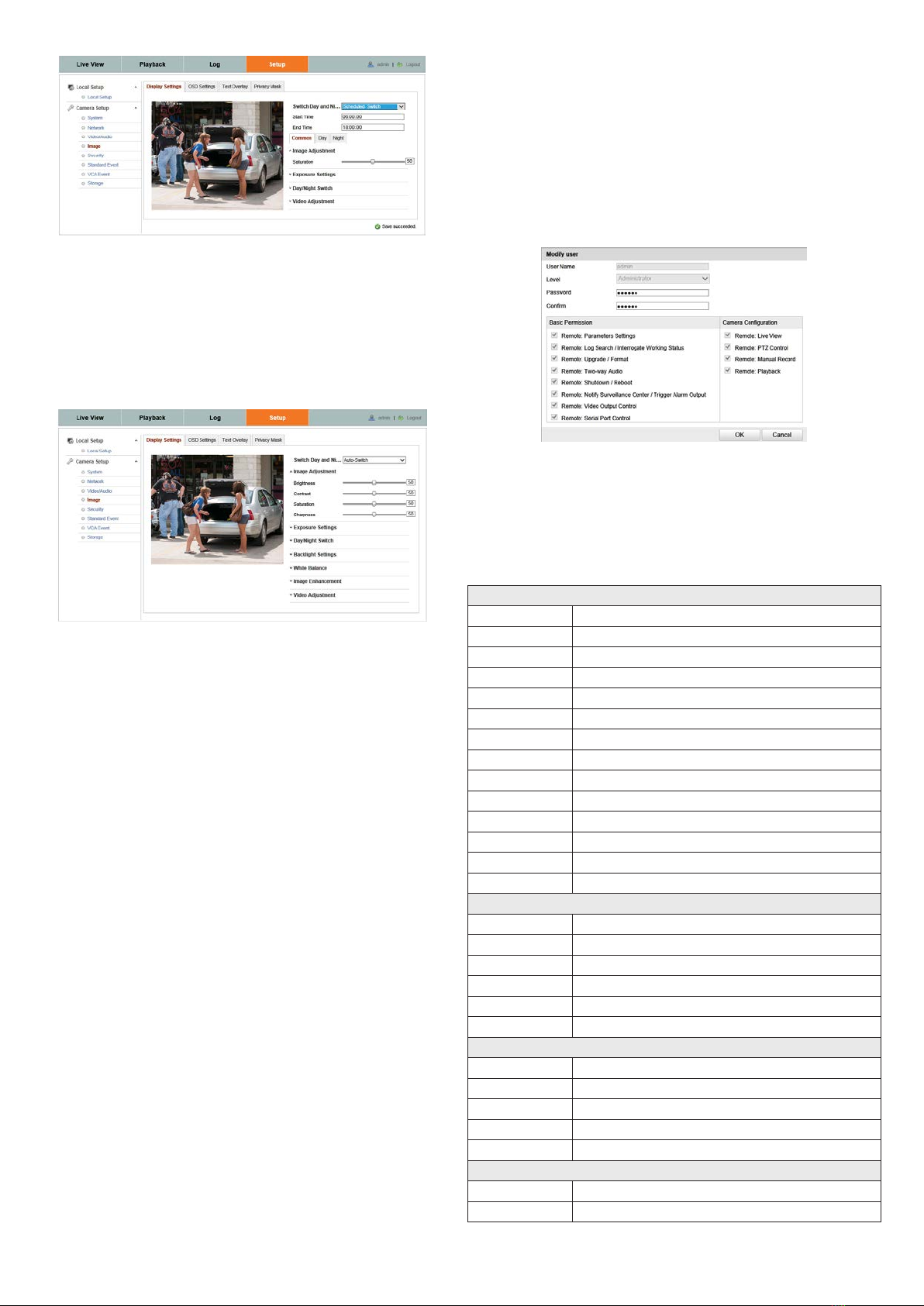
Congurable parameters include:
• Switch Day and Night: Select either Auto-Switch or Scheduled-Switch.
—If using Auto-Switch, open the Day/Night Switch submenu to select the Sensitivity,
Filtering Time, and Smart IR feature ON or OFF.
—If using Scheduled Switch, set the Start Time and End Time of the switch, then open
the Day/Night Switch submenu to select the Smart IR feature ON or OFF.
Also, click the Common, Day and Night tabs to set the Saturation, Hue, Brightness,
Contrast and Sharpness for Day and for Night modes.
• Image Adjustment submenu: Open the Image adjustment submenu to set the Saturation,
Hue, Brightness, Contrast and Sharpness of the video image. Each parameter can be set to a level
of 0 ~ 100 either by moving the slider or entering the value in the box on the right. The eect of
the adjustment will appear in the Live View image in the menu.
• Exposure Settings submenu: In this submenu, set the following for the best performance:
—Iris Mode: Select Auto or Manual. Some cameras may not oer both options.
—Exposure Time: Value ranges from 1/3 to 1/100,000 s. The nominal value is 1/150.
Adjust it according to the lightening condition.
—Gain: Set the gain to show the optimal brightness level.
• Day/Night Switch submenu: You can set the Day/Night switch to Day, Night, Auto, or
Schedule. The option you select determines the submenu options.
—Day or Night: These options both have one parameter: Smart IR.
—Auto: If you select Auto switch, you can set the sensitivity (0 .. 7), ltering time and
Smart IR.
—Schedule: Use Schedule to set that Start Time and End Time for the switch. Smart IR
is also selectable.
• Backlight Settings: Backlight settings include BLC Area (O, Up, Down Left Right Center), the
area to control, and WDR (Wide Dynamic Range) ON or OFF.
• White Balance: White Balance selection is used to correct colors in the image depending on
the lighting source. You can also set the white balance manually (MWB), using Automatic White
Balance (AWB1), and lock the white balance setting (Locked WB).
• Image Enhancement: Options in this submenu include Digital Noise Reduction (DNR) ON or
OFF. If ON, you can also adjust the level of noise reduction.
• Video Adjustment: Video Adjustment includes:
—Mirror: Mirror adjustment enables you to ip the image (Up/Down), ip Left/Right
(reect or Center).
—Rotate: Rotate rotates the image +90 degrees. Rotate and Mirror can be used to adjust
the image in any orientation.
—Video Standard: Select 60 Hz for NTSC format.
—Capture Mode: To make a complete use of the 16:9 aspect ratio, you can enable the
capture mode when you use the camera in a narrow view scene.
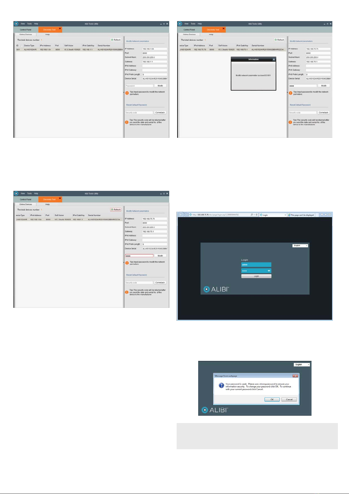
Step 7. Change default password
Observint Technologies strongly recommends that you change the default admin user password in
your camera from “1111” to a dierent code to help protect against unauthorized access. You must
login to the camera with the admin user name to change the admin password. To change the admin
password:
1. Click the Setup tab, and then click Security in the left frame.
2. Click the User tab in the menu on the right.
3. Click the admin User Name to select (highlight) it, and then click the Modify button. The
Modify User pop-up window will open.
4. In both the Password and Conrm elds, enter a new password. The password can contain 0
.. 9,
A .. Z, and a .. z. Record your new password for future reference.
5. Click the OK button at the bottom of the window.
Specications
Camera
Image Sensor 1/3” CMOS
Scanning Mode Progressive Scan
Resolution Up to 2688 x 1520
Eective Pixels Approx. 4.0 Megapixel
Minimum Illumination Color: 0.01 Lux. B/W: 0 Lux (IR ON)
Day/Night True Day/Night ICR)
Electronic Shutter (sec) 1/3 ~ 1/10,000
Wide Dynamic Range 120 dB
Gain Control Auto
White Balance Mode Auto
Noise Reduction 3D DNR
IR Illuminators Smart IR Array, 850 nm
IR Array Range 265 ft
IR Sensitivity 700 - 1100 nm
Lens
Lens Type Fixed
Focal Length 4 mm
Iris Fixed
Focus Manual
Horizontal Viewing Angle 83°
F-number F2.0
Video
Video Compression Format H.264 (Main Prole), H.264 OVC (Optimized Video Codec), MJPEG
Codec Streaming Capability Dual Streaming
Maximum Frame Rate 20 fps @ 2688 x 1520
Bit Rate 32 kbps ~ 16 Mbps
Bit Rate Mode CBR, VBR
Audio
Audio Streaming Two-way
Audio Compression Format 64 Kbps (G.711) / 16 Kbps (G.726) / MP2L2

6www.observint.com © 2016 Observint Technologies. All rights reserved.
Features
Motion Detection Support, Zone Congurable
Backlight Compensation Support, Zone Congurable
Event Notication Email, FTP
Privacy Mask Support
Video Analytics Tamper Detection, Line Crossing, Intrusion Detection
Interface
Ethernet RJ-45 10/100 BASE-T
Network
Protocols TCP/IP, ICMP, HTTP, HTTPS, FTP, DHCP, DNS, DDNS, RTP, RTSP, RTCP, PPPoE, NTP, UPnP, SMTP,
SNMP, IGMP, 802.1X, QoS, IPv6, Bonjour, ONVIF, PSIA
Security One-key reset, ash-prevention, dual streams, heartbeat, mirror, password protection,
privacy mask, Watermark, IP address ltering, Anonymous access
Network Storage NAS (supports NFS, CIFS/SMB)
General
Power Requirements PoE (IEEE802.3af) / 12 Vdc
Power Consumption 5.5 W max (IR OFF), 10.5 W max (IR ON)
Weight 2.65 bs
Dimensions 3.4” H x 3.35” W x 11.8” D
Operating Temperature -22°F ~ 140°F
Operating Humidity 0% ~ 95% RH, Non-condensing
Ingress Protection IP67
Color White/Black
Material Aluminum (Body) / Plastic (sun shield)
Approvals CE, FCC, RoHS
System requirements
Operating System Microsoft®Windows® XP / Vista / 7 / 8 / 10, Apple® OSX
Processor Intel® Pentium® 4 3.0 GHz or later
Memory 1GB or above RAM
Display 1024 x 768 resolution or higher
Web Browser Internet Explorer® 6.0 or above, Apple® Safari® 5.02 or above, Mozilla® Firefox® 3.5 or above
Supplied Accessories
CD ROM (User’s Guide, Installation Tools)
Quick Installation Guide
Mounting Hardware and Template
Junction box
Gang box adaptor plate
Table of contents