2www.observint.com
conduit port on the side of the camera back box, through the mounting surface or into an electrical box, if
used.
Before installation:
• Make sure that the device is in good condition and all the assembly parts are included.
• IR Reection Prevention: Avoid mounting the camera near reective surfaces. The IR light from
the camera can reect back into the lens. Do not remove the plastic cover until the cover is installation
is complete.
• Check the specication of the products for the installation environment.
• Make sure that the wall or the ceiling is strong enough to withstand 3 times the weight of the camera.
• To avoid re or shock hazard, use only UL listed power supplies. Verify that the power supply will
provide the rated voltage and wattage for the camera. See the Specications section.
During installation:
• Monitor impedance: You can attach the CVBS drop cable to a setup monitor. Ensure that the
monitor input impedance is set to 75 Ω.
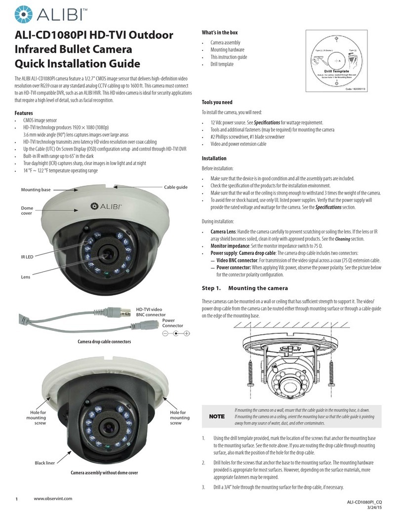
• Camera drop cable: The camera drop cable includes three connectors:
—Video BNC connector (gray): Provides the video signal for transmission across a coax (75 Ω)
extension cable.
—Power connector: The camera can be powered 12 Vdc voltage. Observe the polarity (+/ −)
shown on the power connector.
The following procedure outlines an installation of the camera to a mounting surface. Your installation
steps may dier, depending on how the camera is mounted and how the drop cable connects to video and
power extension cables. To install the camera onto a surface:
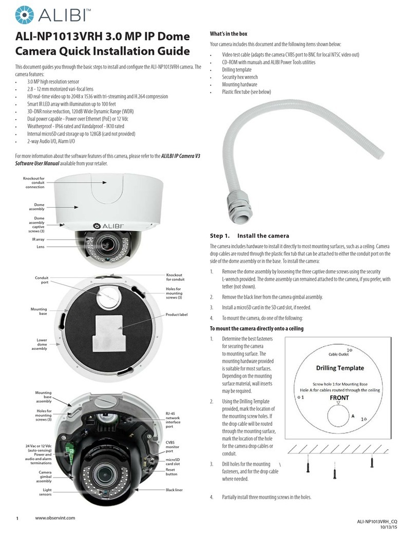
1. Separate the camera dome cover assembly from the camera module by loosening the three captive
dome screws using the security L-wrench provided. Note that the dome cover is tethered to the
camera module.
2. Remove the camera module assembly from the back box after loosing the three captive screws.
Note that the camera module may be tethered to the back box.
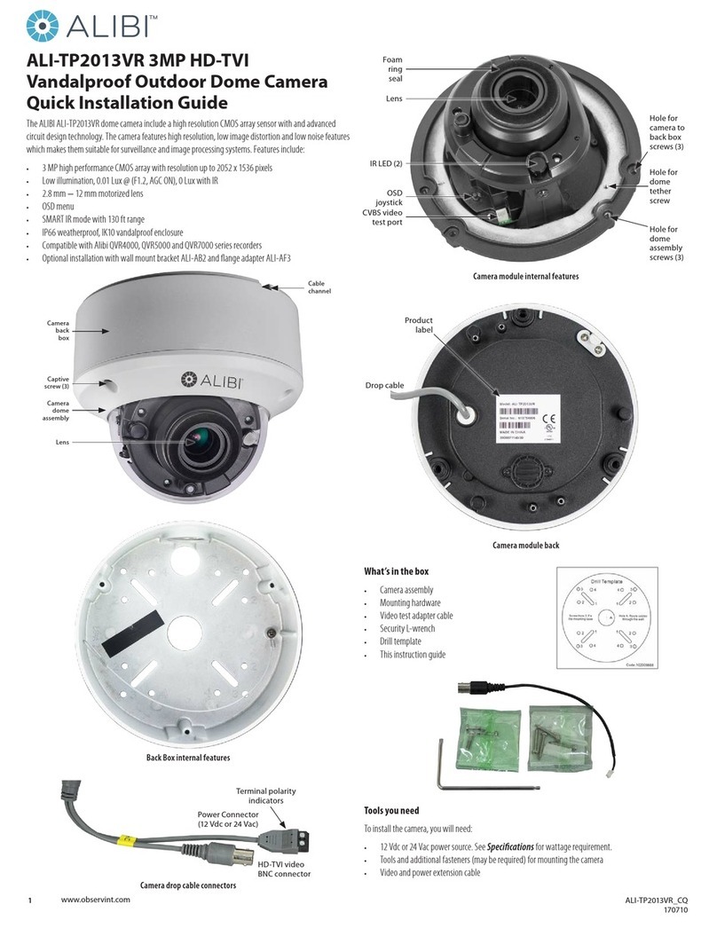
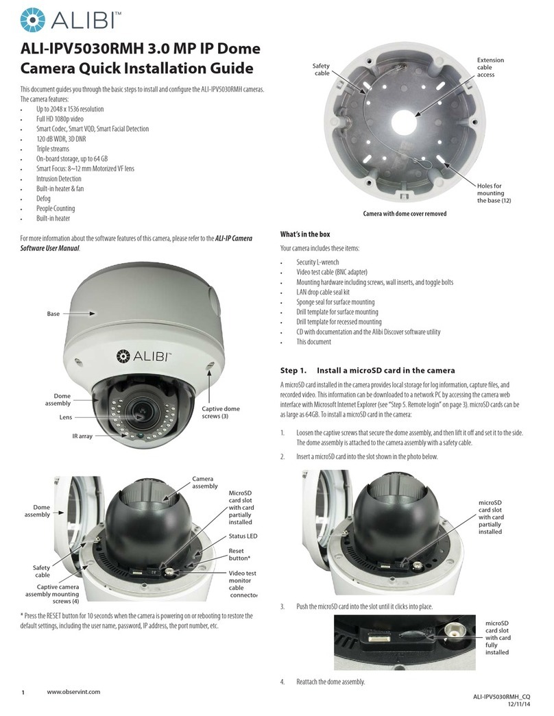
3. Using the drill template or the back box (see page 1), mark the locations of the mounting screw
holes, and the hole for the drop cable if routing the cable through the mounting surface.
NOTE Several holes are provided in the back box for mounting it onto a surface, a gang box and in other
congurations. Use at least four screws to back box to the mounting surface.
4. Using appropriate fasteners, secure the back box to the mounting surface or gang box. The
mounting screws and wall inserts are adequate for surface types.
5. Route power and video extension cables from your power source and monitoring equipment to the
mounting location. Do not apply power to the power extension cable at this time. If the extension
cables will be attached to the camera drop cables within the back box, route the cables into the
housing.
NOTE
Camera drop cable connectors are not waterproof. Seal if needed.
Seal holes drilled into any exterior surface with caulk or other sealant to block moisture and other
contaminants.
6. Connect the camera drop cables to the video and power extension cables, and then secure the
camera module to the back box using the security L-wrench provided. Tighten the screws until snug.
NOTE
The video cable must attach to compatible equipment. If the video cable will attach to NTSC
compatible equipment, set the HD-TVI - CVBS switch on the camera module appropriately. See the
photo on page 1.
The CVBS video cable can attach to any equipment compatible with an NTSC signal.
7. Apply power to the camera. Use caution to observe the DC power polarity shown in the photo on
page 1.
8. Verify that a video signal can be seen on your video monitoring equipment.
Step 2. Adjust the camera for your surveillance target
1. Observe the live video on your monitoring equipment, or plug the video test cable provided into the
mating plug on the camera module and then into a local video setup monitor (not provided).
2. To adjust the camera pan (direction), grasp the camera gimbal on both sides at the pivot point, then
rotate the as shown in the illustration below to point it at your surveillance target.
Pan: 0° ~355° Tilt: 0° ~75°
Pan adjustment Tilt adjustment
To adjust the tilt (elevation), rock the gimbal as shown above in the right illustration.
To adjust the camera rotation (horizon line), grasp the camera head carefully and rotate it as shown in
the photo below.
Rotate: 0° ~355°
Rotation adjustment
3. Reinstall the camera dome cover assembly. Ensure that the dome is clean of grease and dust to
prevent IR reections. Also, the foam ring around the lens must be seated ush against the inner
surface of the bubble to isolate the lens from the IR LEDS from the lens. Fasten the dome cover to
camera body so that the foam ring and the dome cover are attached seamlessly.
Step 3. Open the OSD menu
The On Screen Display (OSD) provides conguration options for rening the performance of the camera. It
also can be used to block sensitive portions in the eld of view (Privacy).
You can open the OSD menu system using the built-in joystick on the camera, from either the recorder Live
View display or through remote login to the ALIBI recorder.
Opening the OSD Menu using the joystick
The OSD joystick is located on the camera module near the CVBS video test connector (see page 1). The
joystick can be rocked up (toward the camera body - see below), down (away from the camera body),
left and right, and can be pressed in (down toward the back box). Use the OSD joystick is used to open the
OSD menu and navigate through the menus. The OSD menu tree is shown on “OSD Denitions: On-screen
Display (OSD) menus” on page 4.
© 2019 Observint Technologies. All rights reserved.
